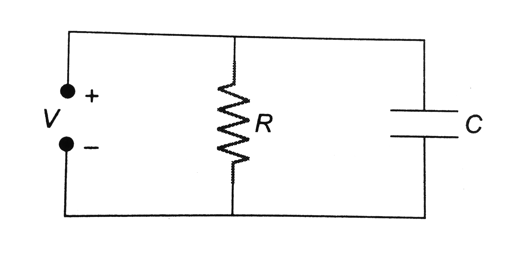
In the circuit shown, a time varying voltage volt is applied where is in second. At time , determine the Current through the resistor and through the capacitor
The correct Answer is:A
At
Further,
constant
Topper's Solved these Questions
- CAPACITORSBOOK - DC PANDEY ENGLISHCHAPTER - CAPACITORSEXERCISE - OBJECTIVE_TYPE
1 Videos
- CAPACITORSBOOK - DC PANDEY ENGLISHCHAPTER - CAPACITORSEXERCISE - OBJECTIVE_TYPE
1 Videos
- ATOMSBOOK - DC PANDEY ENGLISHCHAPTER - ATOMSEXERCISE - MEDICAL ENTRANCES GALLERY
42 Videos
- COMMUNICATION SYSTEMBOOK - DC PANDEY ENGLISHCHAPTER - COMMUNICATION SYSTEMEXERCISE - Subjective
11 Videos
Similar Questions
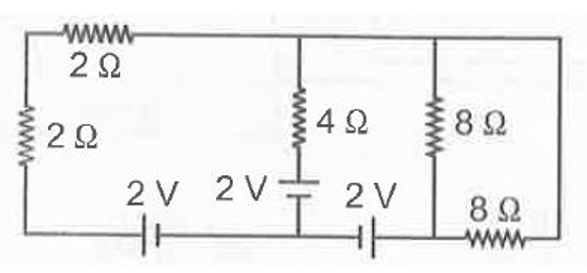
Find the current through 4Ω resistor in the circuit shown in figure.
View SolutionA generator produces a time varying voltage given by V=240sin120t, where t is in second. The rms voltage and frequency are
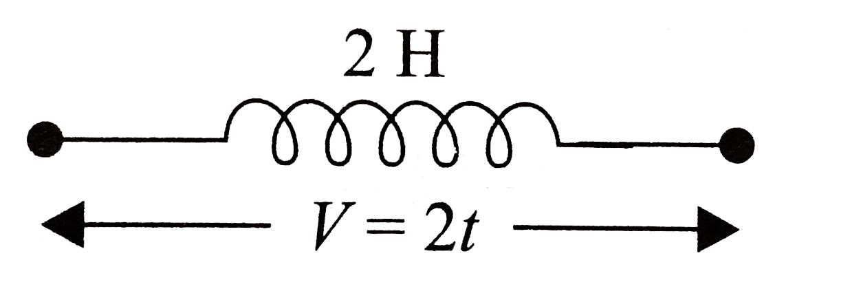
View SolutionA time varying voltage V= 2t (Volt) is applied across and ideal inductor of inductance L =2H as shown in Fig. Then (assume current to be zero at t =0)
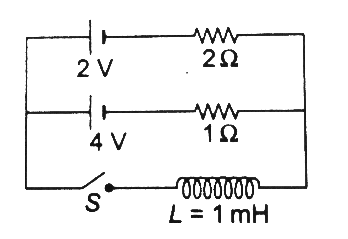
View SolutionIn the circuit shown, switch S is closed at time t=0. Find the current through the inductor as a function of time t.
View SolutionSwitch S is cloesd in the circuit at time t=0. Find the current through the capacitor and the inductor at any time t
View SolutionFor the circuit shown in figure, determine the voltage across 4Ω resistors in volt ?

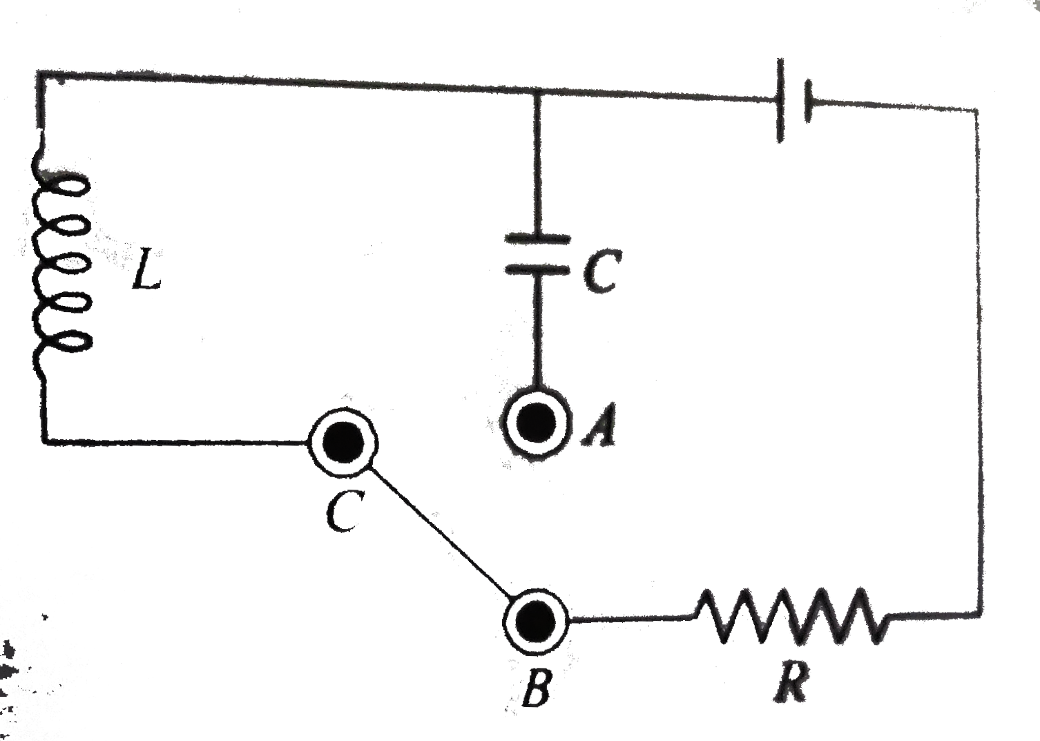
View SolutionIn the circuit shows in Fig the capacitor is initially uncharged and the two - way switch is connected in the position BC. Find the current through the resistence R as a function of time t. After time t=4 ms, the switch is connected in the position AC. Find the frequency of oscillation of the capacitor of the circuit in the position, and the maximum charge on the capacitor C. At what time will the energy stored in the capacitor be one-half of the total energy stored in the circuit? It is given L=2×10⁻⁴H,C=5mF,R=In210Ω and emf of the battery =1V.
View SolutionAn alternating voltage E=E0sinωt , is applied across a coil of inductor L. The current flowing through the circuit at any instant is
View SolutionFor the circuit shown in figure below, at t = 0, switch is closed, the initial current through resistor and final charge on capacitor are

View SolutionThe switch S is closed in the circuit shown at time t=0 . The current in the resistor at t=0 and t=∞ are respectively .
View Solution
