Figure shows two circular rings of radii a & b (a gt b) joined together by wire of negligible resistance. If the arrangement is placed in a time varying magnetic field, dBdt=k and if the resistance per unit length of wire is λ, then induced current is
k(a−b)2λ
k(a+b)2λ
k(a2−b2)2λ(a−b)
k(a2+b2)2λ(a+b)
The correct Answer is:A
To solve the problem, we need to determine the induced current in the arrangement of two circular rings placed in a time-varying magnetic field. Here’s a step-by-step solution:
Step 1: Understand the Setup
We have two circular rings with radii a (larger) and b (smaller), connected by a wire of negligible resistance. The magnetic field is changing with time, represented by dBdt=k.
Step 2: Calculate the Induced EMF for Each Ring
The induced electromotive force (EMF) in each ring can be calculated using Faraday's law of electromagnetic induction, which states that the induced EMF (E) in a closed loop is equal to the negative rate of change of magnetic flux through the loop.
1. For the larger ring (radius a):
E1=dΦdt=ddt(B⋅A)=dBdt⋅πa2
Substituting dBdt=k:
E1=k⋅πa2
2. For the smaller ring (radius b):
E2=dΦdt=ddt(B⋅A)=dBdt⋅πb2
Substituting dBdt=k:
E2=k⋅πb2
Step 3: Calculate the Net EMF
The net EMF (Enet) in the circuit formed by the two rings is the difference between the EMFs of the two rings:
Enet=E1−E2=k⋅πa2−k⋅πb2
Factoring out k⋅π:
Enet=k⋅π(a2−b2)
Step 4: Calculate the Total Resistance
The total resistance R of the wire connecting the two rings can be calculated as follows:
- The circumference of the larger ring is 2πa.
- The circumference of the smaller ring is 2πb.
- The total length of the wire is 2πa+2πb.
The resistance per unit length is λ, so the total resistance R is:
R=λ⋅(2πa+2πb)=2πλ(a+b)
Step 5: Calculate the Induced Current
Using Ohm's law, the induced current I can be calculated as:
I=EnetR
Substituting the values we found:
I=k⋅π(a2−b2)2πλ(a+b)
Simplifying:
I=k(a2−b2)2λ(a+b)
Final Answer
The induced current is:
I=k(a−b)(a+b)2λ(a+b)=k(a−b)2λ
We have two circular rings with radii a (larger) and b (smaller), connected by a wire of negligible resistance. The magnetic field is changing with time, represented by dBdt=k.
The induced electromotive force (EMF) in each ring can be calculated using Faraday's law of electromagnetic induction, which states that the induced EMF (E) in a closed loop is equal to the negative rate of change of magnetic flux through the loop.
E1=dΦdt=ddt(B⋅A)=dBdt⋅πa2
Substituting dBdt=k:
E1=k⋅πa2
E2=dΦdt=ddt(B⋅A)=dBdt⋅πb2
Substituting dBdt=k:
E2=k⋅πb2
The net EMF (Enet) in the circuit formed by the two rings is the difference between the EMFs of the two rings:
Enet=E1−E2=k⋅πa2−k⋅πb2
Factoring out k⋅π:
Enet=k⋅π(a2−b2)
The total resistance R of the wire connecting the two rings can be calculated as follows:
- The circumference of the larger ring is 2πa.
- The circumference of the smaller ring is 2πb.
- The total length of the wire is 2πa+2πb.
R=λ⋅(2πa+2πb)=2πλ(a+b)
Using Ohm's law, the induced current I can be calculated as:
I=EnetR
Substituting the values we found:
I=k⋅π(a2−b2)2πλ(a+b)
Simplifying:
I=k(a2−b2)2λ(a+b)
The induced current is:
I=k(a−b)(a+b)2λ(a+b)=k(a−b)2λ
Topper's Solved these Questions
- ELECTROMAGNETIC INDUCTIONBOOK - AAKASH INSTITUTE ENGLISHCHAPTER - ELECTROMAGNETIC INDUCTIONEXERCISE - Assignment (SECTION - C)
10 Videos
- ELECTROMAGNETIC INDUCTIONBOOK - AAKASH INSTITUTE ENGLISHCHAPTER - ELECTROMAGNETIC INDUCTIONEXERCISE - Assignment (SECTION - D)
6 Videos
- ELECTROMAGNETIC INDUCTIONBOOK - AAKASH INSTITUTE ENGLISHCHAPTER - ELECTROMAGNETIC INDUCTIONEXERCISE - Assignment (SECTION - A)
55 Videos
- ELECTRIC CHARGES AND FIELDS BOOK - AAKASH INSTITUTE ENGLISHCHAPTER - ELECTRIC CHARGES AND FIELDS EXERCISE - comprehension
3 Videos
- ELECTROMAGNETIC WAVESBOOK - AAKASH INSTITUTE ENGLISHCHAPTER - ELECTROMAGNETIC WAVESEXERCISE - ASSIGNMENT SECTION - D Assertion-Reason Type Questions
25 Videos
Similar Questions
Find the equivalent resistance between A and B.

View SolutionFigure 3.15(a) shown two circular rings of radii a and b (a>b) joined together with wires of negligible resistance. Figure 3.15(b) shown thew pattern obtained by folding the small loop in the plane of the large loop.
(a)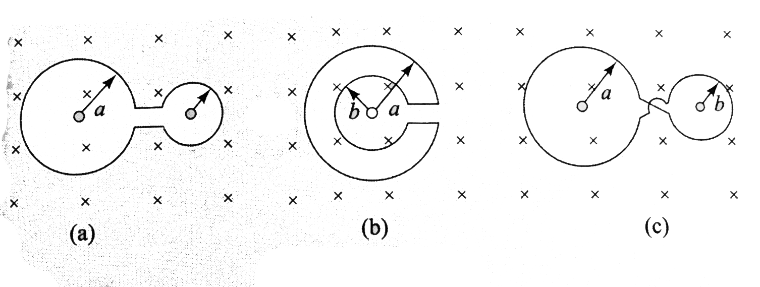
The pattern shown in Fig.3.15( c ) is obtained by twisting the small loop of Fig.3.15(a) through 180∘.
All the three arrangement are placed in a uniform time varying magnetic field dB/dt=k, perpendicular to the plane of the loops. if the resistance per unit length of the wire is λ, then determine the induced current in each case.
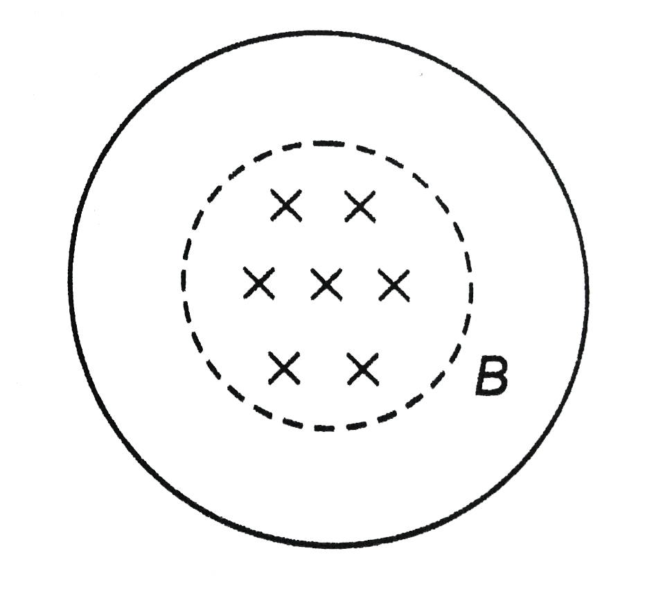
View SolutionThe figure shows a conducting ring of radius R. A uniform steady magnetic field B lies perpendicular to the plane of the ring a circular region r(<R). If the resistance per unit length of the ring is λ, then the current induced in the ring when its radius gets doubled is
View Solutionthe force on current carrying wire placed in uniform magnetic field B as shown in figure is

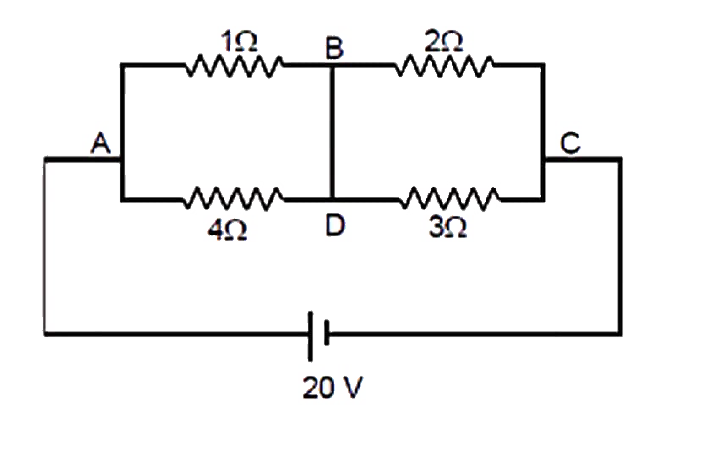
View SolutionIn the given circuit diagram , a connecting wire of negligible resistance is joining the points B and D, the current in the connecting wire is
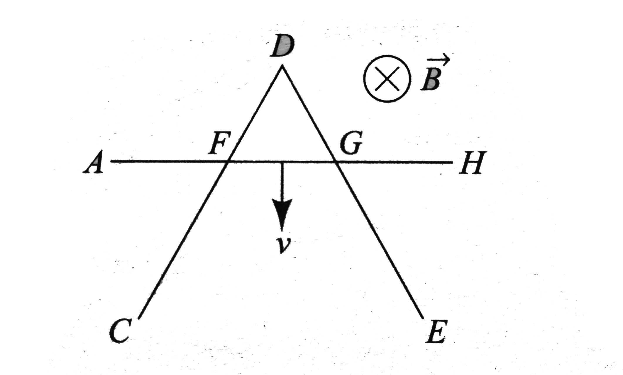
View SolutionA long conducting wire AH is moved over a conducting triangular wire CDE with a constant velocity v in a uniform magnetic field →B directed into the plane of the paper. Resistance per unit length of each wire is ρ. Then
View SolutionFind the magnitude of induced filed " En " at a point r (>R) where a uniform but time varying magnetic field (dBdt=b) exists in a region of radius R .
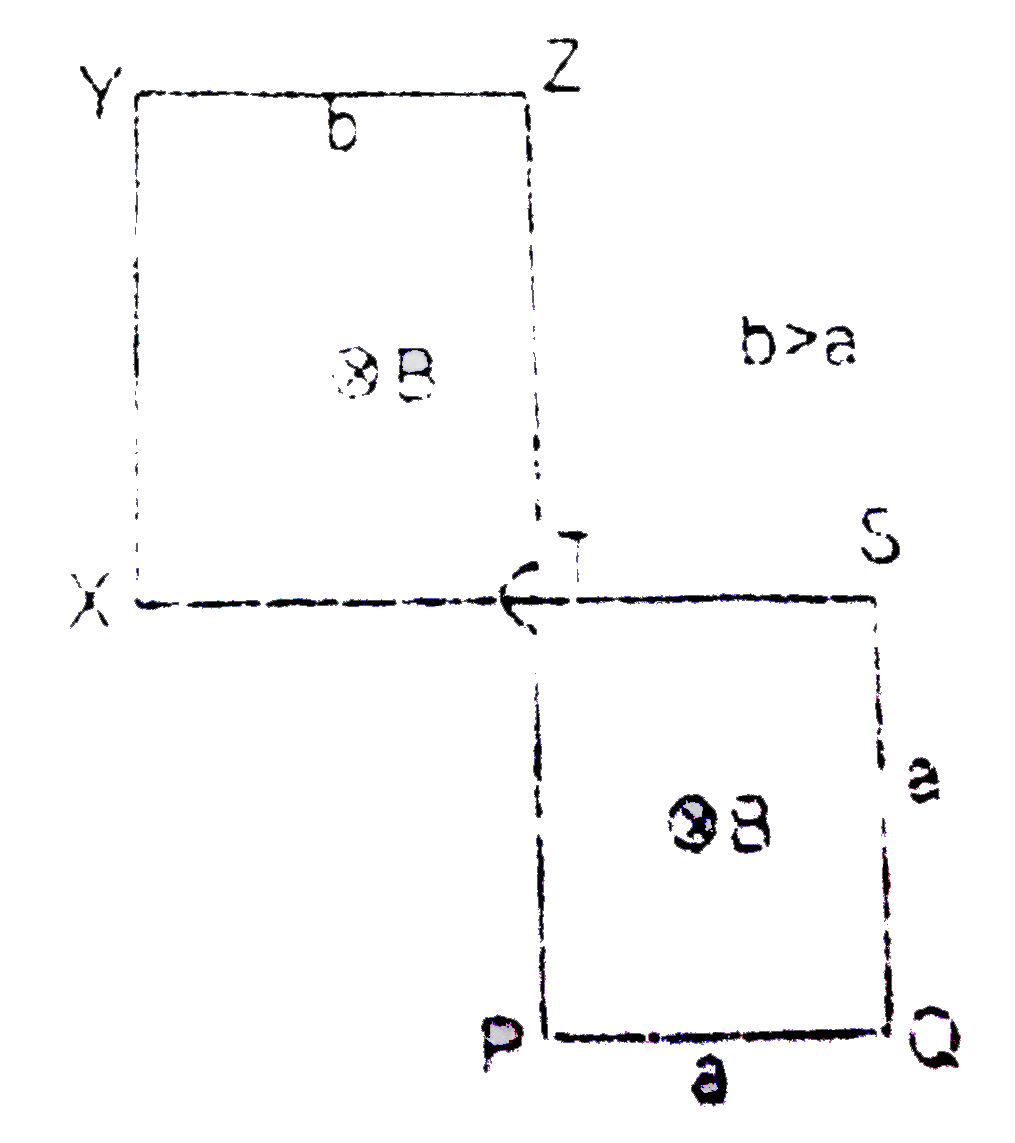
View SolutionFigure shows a wire frame PQSTXYZ placed in a time varying magnetic field given as B=βt, where β is a positive constant.Resistance per unit length of the wire is λ.Find the current induced in the wire and draw its electrical equivalent diagram.
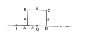
View SolutionThe resistance per unit length of the wires in segments AB, BC, CD, and AD are the same. The magnetic field due to the current at point O is
View SolutionFigure shows a circular region of radius R in which uniform magnetic field B exists. The magnetic field is increasing at a rate dBdt. The induced electric field at a distance r from the centre for r<R is

View Solution
