An unknown transistor needs to be identified as npn and pnp type. A multimeter, wilth +ve and −ve terminals is used to measure resistance between different terminals transistor. If terminal 2 is the base of the transistor then which of the following is correct for a pnp transistor?
+ve terminals 3,−ve terminal 2, resistance high
+ve terminal 2,−ve terminal 3, resistance low
+ve terminal 1,−ve terminal 2, resistance high
+ve terminal 2,−ve terminal 1, resistance high
The correct Answer is:D
To identify whether the unknown transistor is of type npn or pnp, we can use a multimeter to measure the resistance between its terminals. Given that terminal 2 is the base of the transistor, we will analyze the characteristics of a pnp transistor.
1. Understanding the PNP Transistor Structure:
- A PNP transistor consists of two p-type semiconductor materials (P) and one n-type semiconductor material (N) sandwiched between them. The terminals are typically labeled as Emitter (E), Base (B), and Collector (C).
2. Identifying the Terminals:
- In our case, terminal 2 is the base (B). The other two terminals will be the emitter (E) and collector (C). We can label them as follows:
- Terminal 1: Emitter (P)
- Terminal 2: Base (N)
- Terminal 3: Collector (P)
3. Forward and Reverse Bias Conditions:
- For a PNP transistor:
- Forward Bias: The emitter (P) must be at a higher potential than the base (N). This means if we connect the positive terminal of the multimeter to the emitter (Terminal 1) and the negative terminal to the base (Terminal 2), we will observe low resistance.
- Reverse Bias: If we connect the positive terminal to the base (Terminal 2) and the negative terminal to the emitter (Terminal 1), we will observe high resistance.
4. Using the Multimeter:
- To determine the type of transistor, we can measure the resistance between the terminals:
- Measure between Terminal 1 (Emitter) and Terminal 2 (Base):
- If the multimeter shows low resistance, it indicates forward bias (which is expected for a PNP transistor).
- Measure between Terminal 2 (Base) and Terminal 1 (Emitter):
- If the multimeter shows high resistance, it indicates reverse bias.
5. Conclusion:
- Based on the measurements:
- If Terminal 1 is connected to the positive terminal of the multimeter and Terminal 2 to the negative, we expect low resistance (forward bias).
- If Terminal 2 is connected to the positive terminal and Terminal 1 to the negative, we expect high resistance (reverse bias).
- Therefore, the correct option for identifying a PNP transistor when Terminal 2 is the base is that the resistance will be high when the base is connected to the positive terminal of the multimeter and the emitter to the negative terminal.
Final Answer:
The correct option for a PNP transistor, when Terminal 2 is the base, is that it shows high resistance when the base is connected to the positive terminal of the multimeter.
- A PNP transistor consists of two p-type semiconductor materials (P) and one n-type semiconductor material (N) sandwiched between them. The terminals are typically labeled as Emitter (E), Base (B), and Collector (C).
- In our case, terminal 2 is the base (B). The other two terminals will be the emitter (E) and collector (C). We can label them as follows:
- Terminal 1: Emitter (P)
- Terminal 2: Base (N)
- Terminal 3: Collector (P)
- For a PNP transistor:
- Forward Bias: The emitter (P) must be at a higher potential than the base (N). This means if we connect the positive terminal of the multimeter to the emitter (Terminal 1) and the negative terminal to the base (Terminal 2), we will observe low resistance.
- Reverse Bias: If we connect the positive terminal to the base (Terminal 2) and the negative terminal to the emitter (Terminal 1), we will observe high resistance.
- To determine the type of transistor, we can measure the resistance between the terminals:
- Measure between Terminal 1 (Emitter) and Terminal 2 (Base):
- If the multimeter shows low resistance, it indicates forward bias (which is expected for a PNP transistor).
- Measure between Terminal 2 (Base) and Terminal 1 (Emitter):
- If the multimeter shows high resistance, it indicates reverse bias.
- Based on the measurements:
- If Terminal 1 is connected to the positive terminal of the multimeter and Terminal 2 to the negative, we expect low resistance (forward bias).
- If Terminal 2 is connected to the positive terminal and Terminal 1 to the negative, we expect high resistance (reverse bias).
- Therefore, the correct option for identifying a PNP transistor when Terminal 2 is the base is that the resistance will be high when the base is connected to the positive terminal of the multimeter and the emitter to the negative terminal.
The correct option for a PNP transistor, when Terminal 2 is the base, is that it shows high resistance when the base is connected to the positive terminal of the multimeter.
Topper's Solved these Questions
Similar Questions
A working transistor with its three legs marked P,QandR is tested using a multimeter No conduction is found between P,Q by connecting the common (negative) terminal of the multimeter to R and the other (positive) terminal to P or Q some resistance is seen on the multimeter . Which of the following is true for the transistor ?
View SolutionA working transitor with its three legs marked P,QandR is tested using a multimeter No conduction is found between 'P',Qby connecting the common (negative) terminal of the multimeter to Rand the other (positive) terminal to P or Q some resistance is seen on the multimeter . Which of the following is true for the transistor ?
View SolutionA working transitor with its three legs marked P,QandR is tested using a multimeter No conduction is found between P,Qby connecting the common (negative) terminal of the multimeter to Rand the other (positive) terminal to or Q some resistance is seen on the multimeter . Which of the following is true for the transistor ?
View SolutionAssertion : In common base configuration, the current gain of the transistor is less than unity.
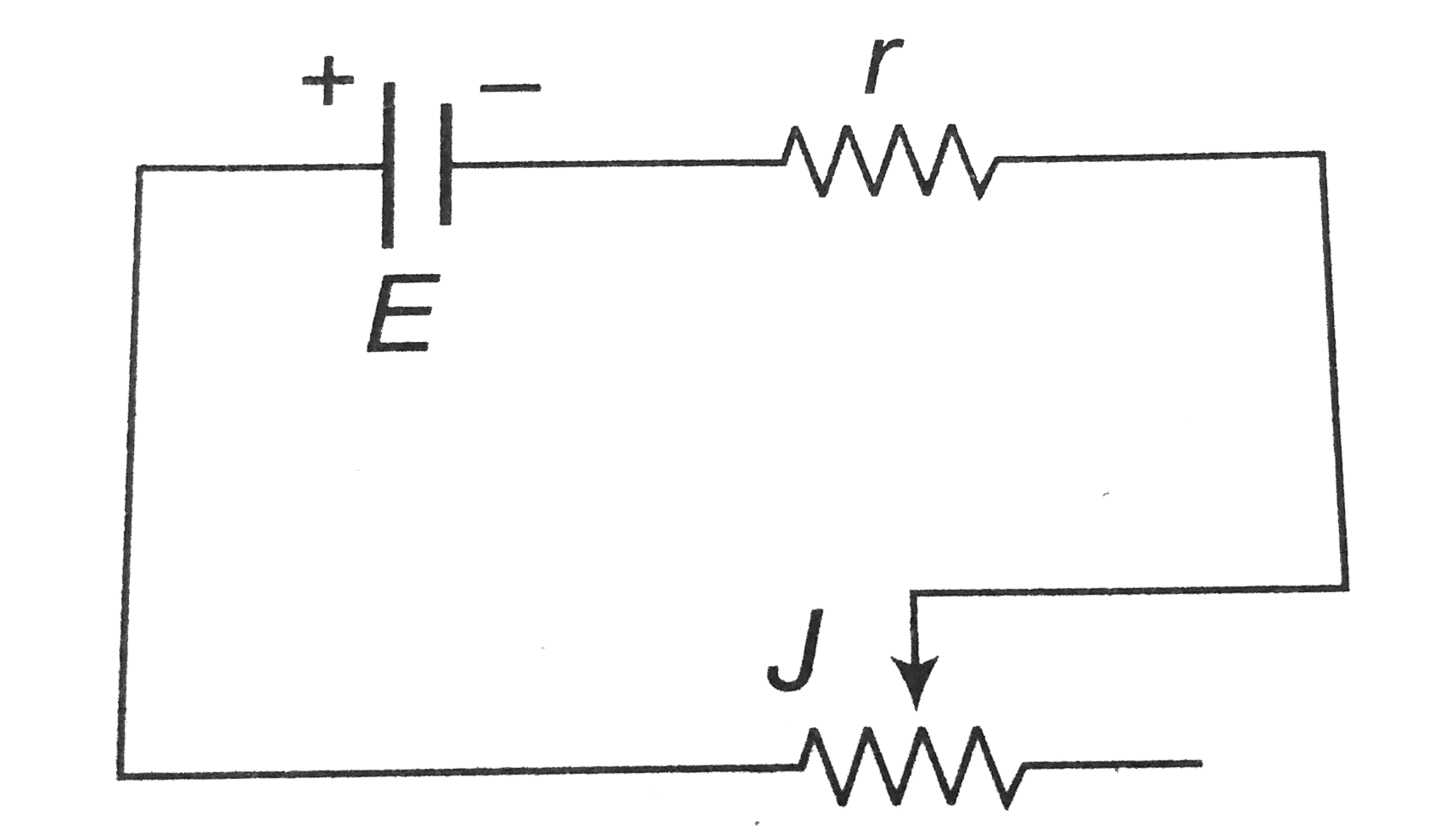
Reason : The collector terminal is revers biased for amplification.View SolutionBattery shown in figure has e.m.f. E and internal resistance r. Current in the circuit can be varied by sliding the contact J. If at any instant current flowing through the circuit is I, potential difference between terminals of the cells is V, thermal power generated in the cell is equal to η fraction of total electrical power generated in it, then which of the following graphs is correct ?
 View Solution
To identify whether the transistor is working or not, using multimeter, which statement serves the purpose?
View SolutionConsider the transistor shown in figure, its terminals are marked as 1,2 and 3. Using multimeter one try to identify the base of transistor, he proceed in the way as follows. Experiment I: He touches the common lead of the multimeter to 2, then on touching other lead of multimeter to 1 he hasn.t got any beep (indication of conduction) but when connected to 3 got the beep.
Experiment II: He connected the common lead of multimeter to 1 and other lead to 2 and 3 one by one then in this case he got beep for both connections. From this we conclude that
 View Solution
An n-p-n transistor in a common - emitter mode is used as a simple voltage amplifier with a collector current of 4 mA. The positive terminal of a 8 V battery is connected to the collector through a load resistance RL and to the base through a resistance RB . The collector - emitter voltage VCE=4V , the base - emitter voltage VBE=0.6V and the current amplification factor β=100 . Calculate the values of RL and RB .
View SolutionA battery consists of a variable number n of identical cells having internal resistance connected in series. The terminals of the battery are short circuited and the current I measured. Which one of the graph below shows the correct relationship between I and n?
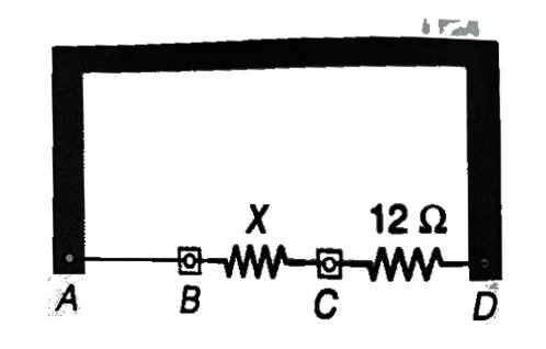
View SolutionA thin uniform wire AB of length 1m, an unknown resistance X and a resistance of 12Ω are connected by thick conducting strips, as shown in the figure. A battery and a galvanometer (with a sliding jockey connected to it) are also available. Connections are to be made to measure the unknown resistance X. Using the principle of Wheatstone bridge answer the following questions :
(a) Are there positive and negative terminals on the galvanometer?
(b) Copy the figure in your answer book and show the battery and the galvanometer (with jockey connect at appropriate points.
(c) After appropriate connections are made, it is found that no deflection takes place in th, from galvanometer when the sliding jockey touches the wire at a distance of 60cm from A. Obtain value of the resistance X.
 View Solution

