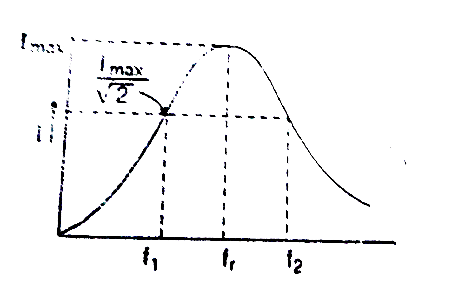
Draw a curve for showing variation in alternating current with frequency in LCR resonant circuit.Hence obtain an expression of bandwidth.
There are two half power frequencies f1 and f2:
(a)Lower half power frequency (f1):
This half power frequency is less than the resonant frequency fr, At this frequency the circuit is capacitive.
(b )Upper half power frequency (f2):
This half-power is greater than the resonant frequency fr.At this frequency the circuit is inductive.
Band width (Δf):
The difference of half-power frequencies f1 and f2 is called band-width (Δf)
Band width Δf=(f2−f1)
For series resonant circuit :
Δf=12π(RL)

Topper's Solved these Questions
- ALTERNATING CURRENTBOOK - RESONANCE ENGLISHCHAPTER - ALTERNATING CURRENTEXERCISE - A.L.P
10 Videos
- ALTERNATING CURRENTBOOK - RESONANCE ENGLISHCHAPTER - ALTERNATING CURRENTEXERCISE - EXAMPLE
40 Videos
- ALTERNATING CURRENTBOOK - RESONANCE ENGLISHCHAPTER - ALTERNATING CURRENTEXERCISE - Exercise -3 Part-2
3 Videos
- ATOMIC PHYSICSBOOK - RESONANCE ENGLISHCHAPTER - ATOMIC PHYSICSEXERCISE - Advanved level problems
17 Videos
Similar Questions
Knowledge Check
To reduce the resonant frequency in an LCR series circuit with a generator
Athe generator frequency should be reduced.Banother capacitor should be added in parallel to the first.Cthe iron core of the inductor should be removed.Ddielectric in the capacitor should be removed.At resonance frequency the impedance in series LCR circuit is
AmaximumBminimumCzeroDinfinity
To reduce the resonant frequency in an LCR series circuit with a generator
View SolutionDraw a labelled graph showing variation of impedance of a series LCR circuit with frequency of the a.c. supply.
View SolutionAs the frequency of an alternating current increases, the impedance of the circuit
View SolutionA device X is connected across an ac source of voltage V=V0sinωt. The current throught X is given as I=I0sin(ωt+π2)
(a) Identify the device X and write the expression for its reactance.
(b) Draw graph showing variation of voltage and current with time over one cycle of ac, for X.
How does the reactance of the device X vary with frequency of the ac? Show this variation graphically.
(d) Draw the phasor diagram for the device X.
View SolutionDraw a labelled graph showing the variation of inductive reactance (XL) verses frequency (f)
View SolutionThe figure shows the graphical variation of the reactance of a capacitor with frequency of ac source. (a) find the capacitance of the capacitor (b)an ideal inductor has the same reactance at 100 Hz frequency as the capacitor has the same frequency find the value of the inductor. (c) draw the graph showing the variation of the reactance of this inductor with frequency

View Solution