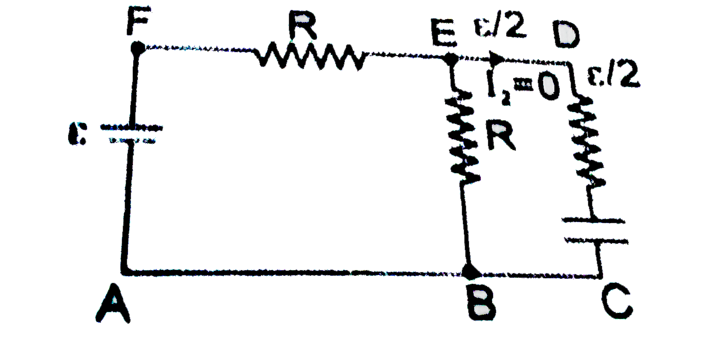
In the circuit shown in the figure, the switch S is initially open and the capacitor is initially uncharged. I1,I2 and I3 represent the current in the resistance 2Ω,4Ω and 8Ω respectively.
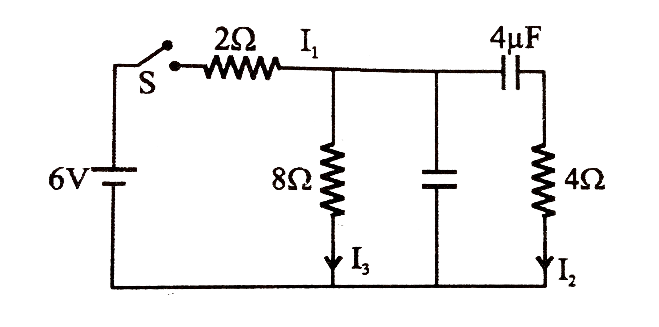
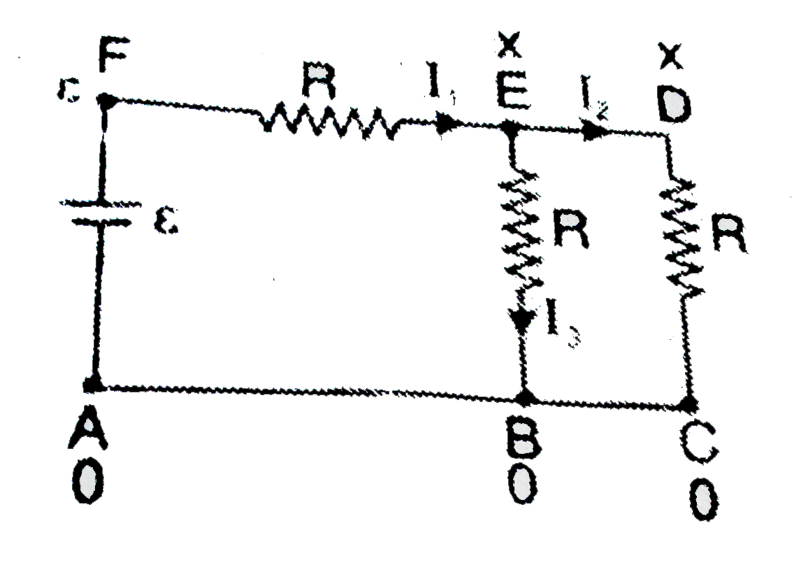
(a) Initially the capacitor is uncharged so its behaviour is like a conductor. Let potential at A is zero so at B and C also zero and at F it is ε. Let potential at E is x so at D also x. Apply Kirchhoff's Ist law at point E :
x−εR+x−0R+x−0R=0⇒3xR=εR
x=ε3,Qc=0
∴I1=−ε/3+εR=2ε3R⇒I2=dQDt=ε3R and I3=ε3R
Alternatively
i1=εReq=εnR+R2=2ε3R⇒i2=i3=i12=ε3R and dQdt=i2=ε3R
(b) at t=∞ (finally)
capacitor completely charged so their will be no current through it.
I2=0,I1=I3=ε2R
VE−VB=VD−Vc=(ε/2R)R=ε/2
⇒QC=εC2,dQdt=I2=0

Topper's Solved these Questions
- CAPACITANCEBOOK - RESONANCE ENGLISHCHAPTER - CAPACITANCEEXERCISE - Miscellaneous Solved Example
3 Videos
- CAPACITANCEBOOK - RESONANCE ENGLISHCHAPTER - CAPACITANCEEXERCISE - Exercise - 1
79 Videos
- ATOMIC PHYSICSBOOK - RESONANCE ENGLISHCHAPTER - ATOMIC PHYSICSEXERCISE - Advanved level problems
17 Videos
- COMMUNICATION SYSTEMSBOOK - RESONANCE ENGLISHCHAPTER - COMMUNICATION SYSTEMSEXERCISE - Exercise 3
13 Videos
Similar Questions
Knowledge Check
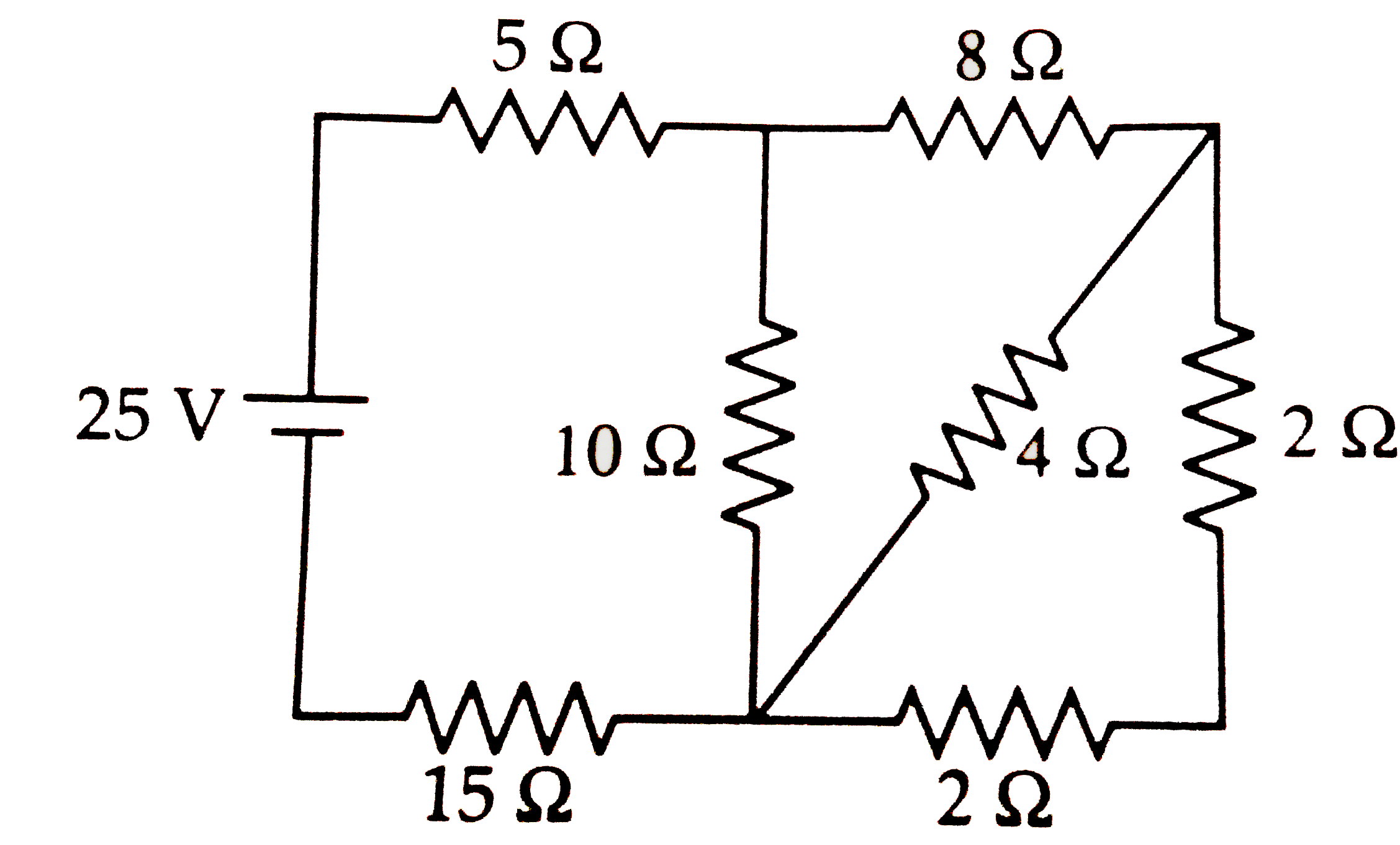
For the circuit shown in the figure, the current in the 4Ω resistor is
 A0.5AB0.25AC1AD1.5A
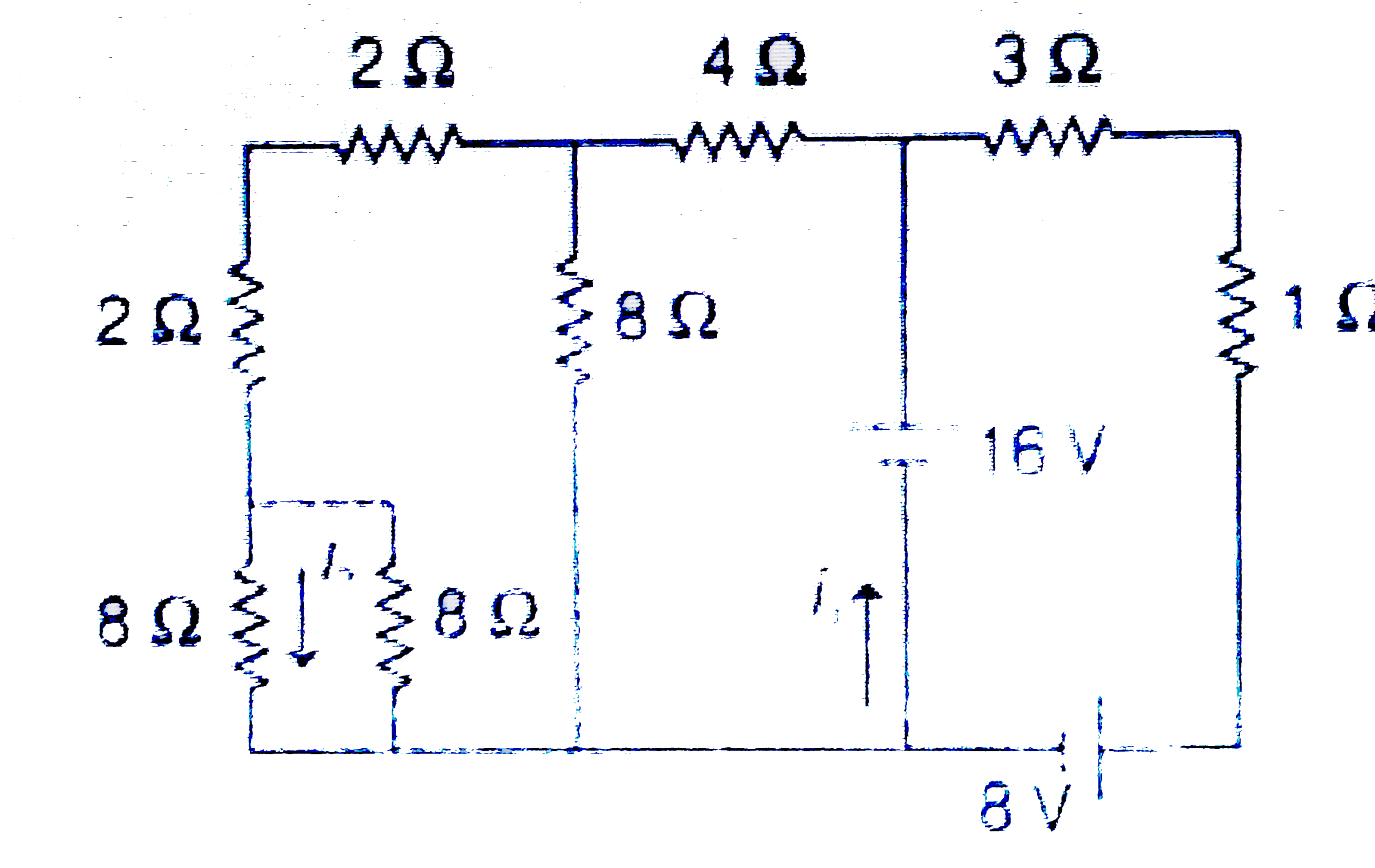
In the circuit shown in figure ,find the ratio of currents i1/i2.
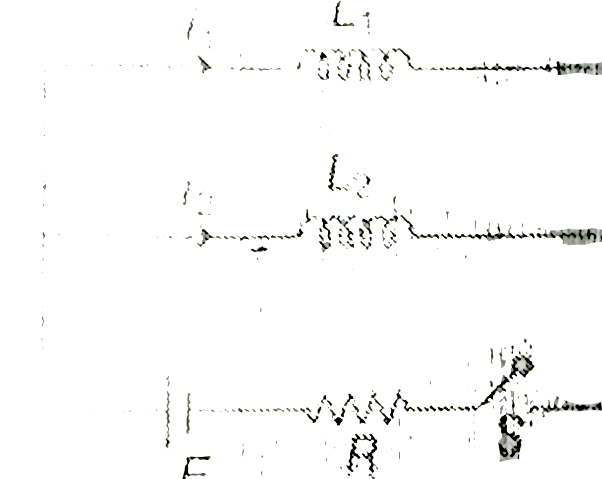
View SolutionIn the circuit shown in the figure The steady state currents i1andi2 in the coils after the switch S is closed are
View SolutionIn the circuit shown E,F,G and H are cells of emf 2V,1V,3V and 1V respectively and their internal resistance are 2Ω,1Ω,3Ω and 1Ω respectively.
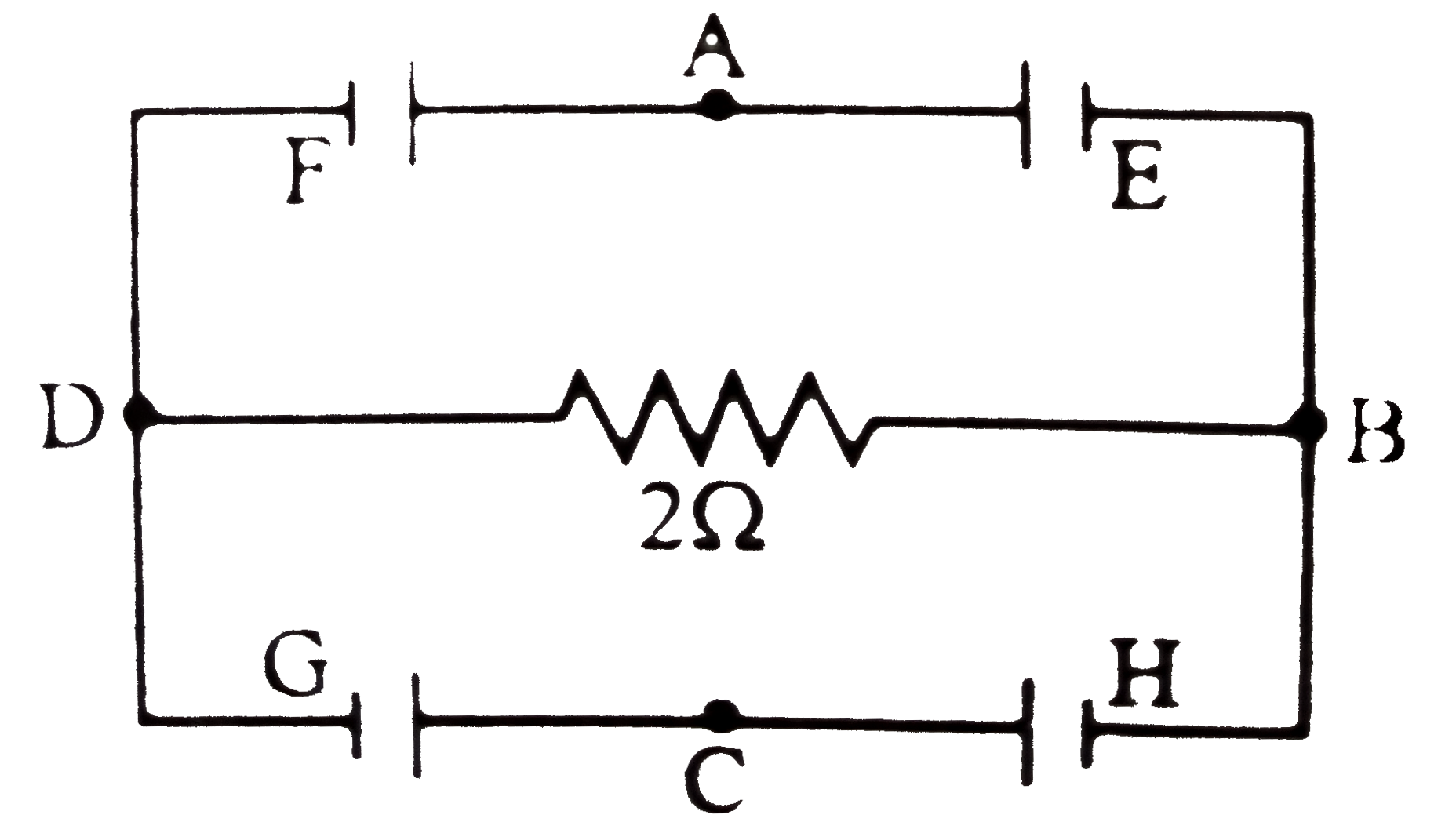
View SolutionIn the circuit shown E,F,G and H are cells of emf 2V,1V,3V and 1V respectively and their internal resistance are 2Ω,1Ω,3Ω and 1Ω respectively.

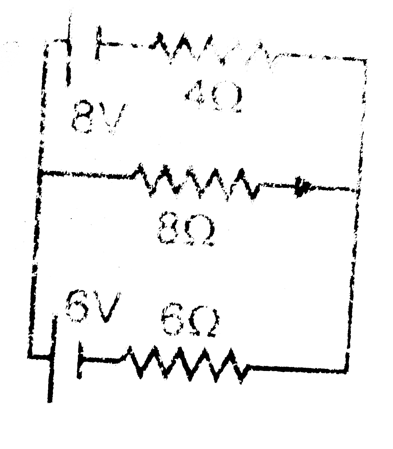
View SolutionThe current in 8Ω resistance is (as per given circuit)
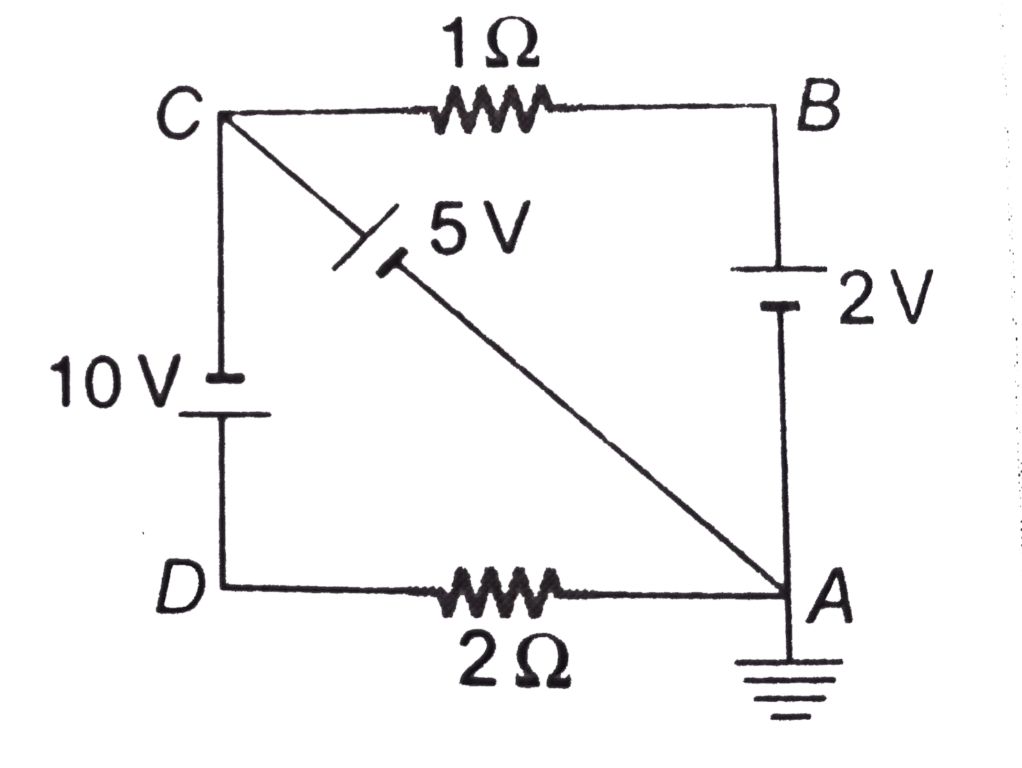
View SolutionIn the circuit shown in figure find the potentials of A,B,C and D and the current through 1Ω and 2Ω resistance.
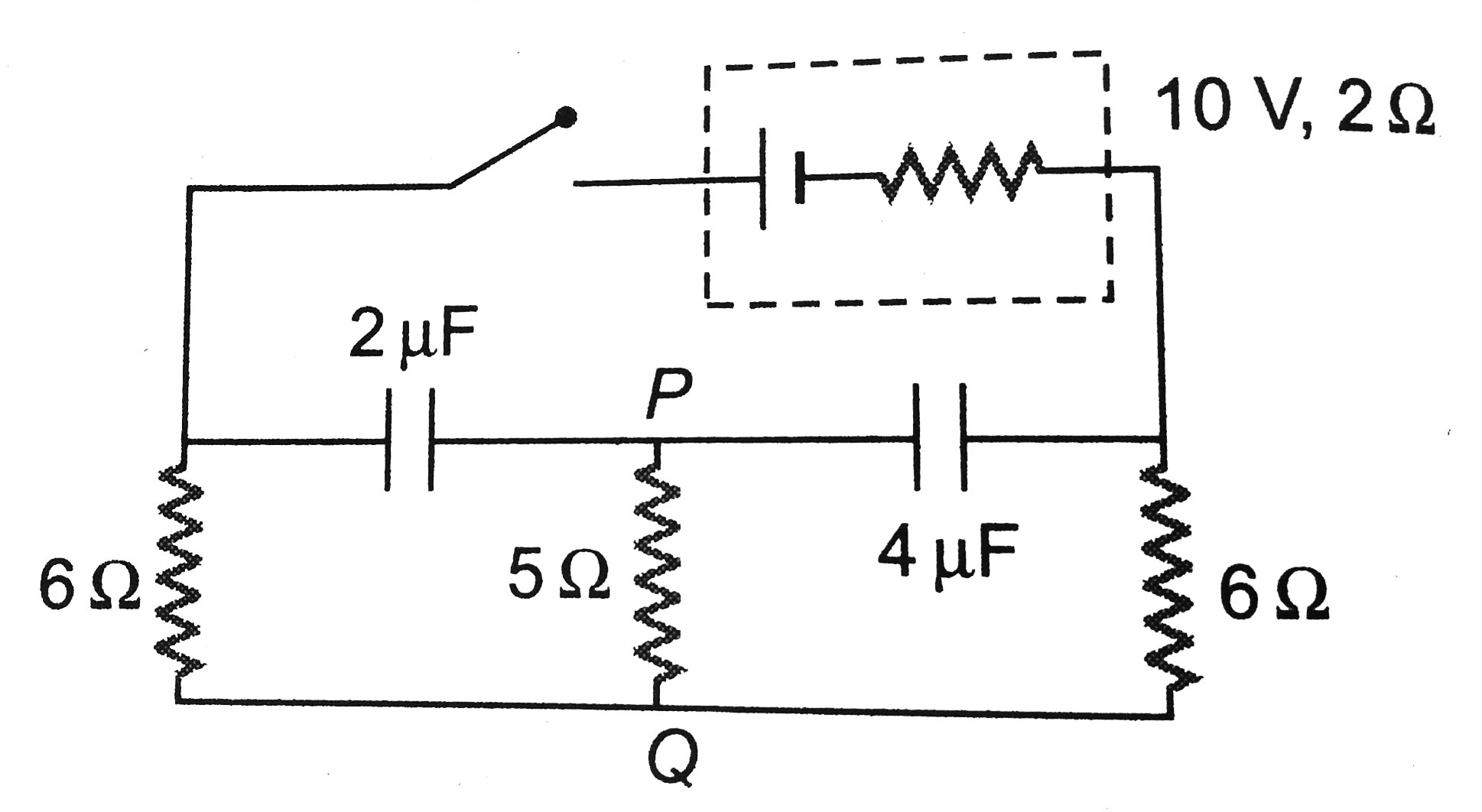
View SolutionIn the circuit shown in figure, the capacitors are initially uncharged. The current through resistor PQ just after closing the switch is
View Solution

