The resistance of each resisor in the circuit diagram shown in figure is the same and equal to The voltage across the terminals is U = 7V. Determine the current current i(Ampere) the jeads if their resistance can be neglected.
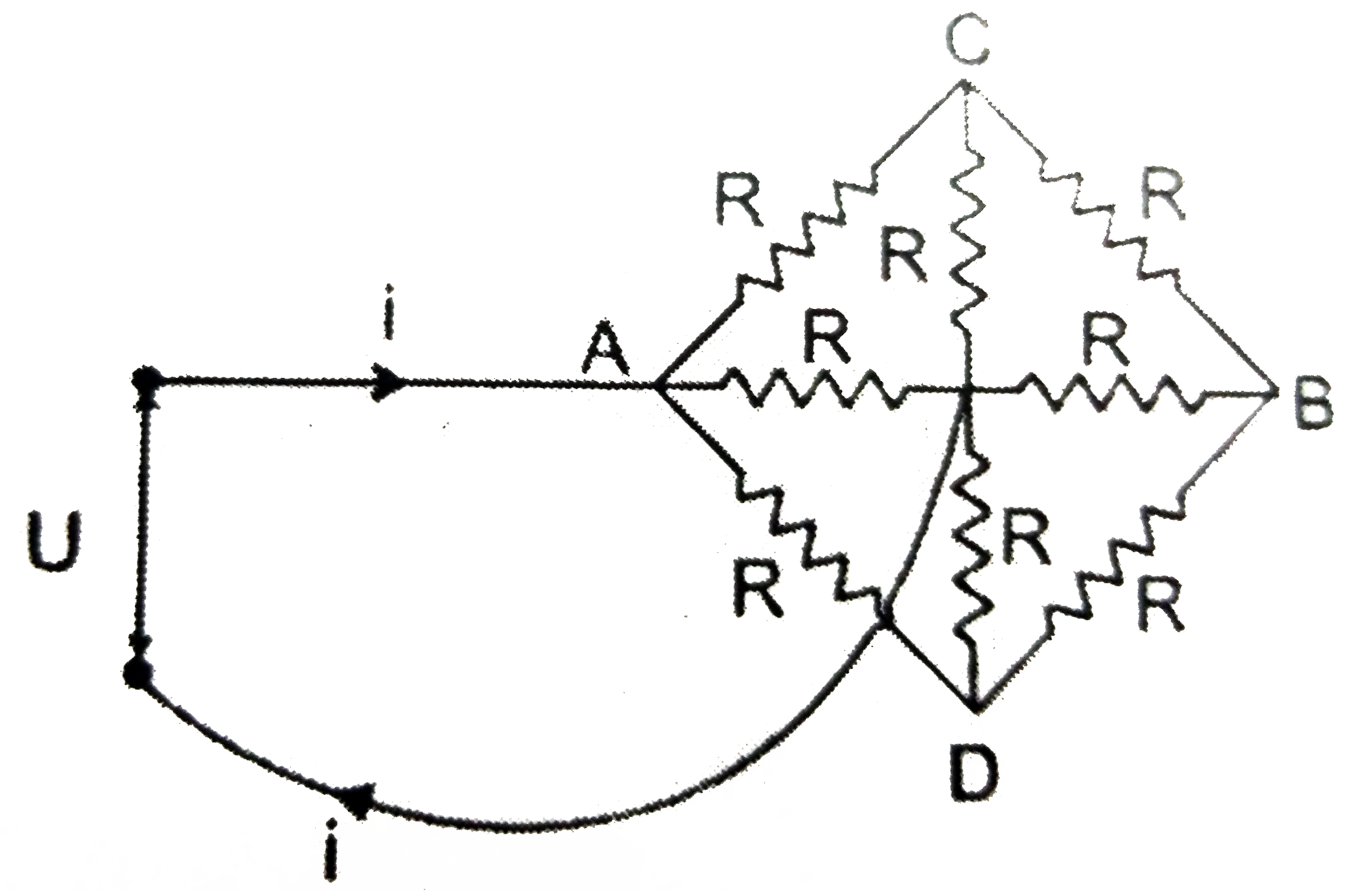
The correct Answer is:15
Step by step video & image solution for The resistance of each resisor in the circuit diagram shown in figure is the same and equal to R=1Omega The voltage across the terminals is U = 7V. Determine the current current i(Ampere) the jeads if their resistance can be neglected. by Physics experts to help you in doubts & scoring excellent marks in Class 12 exams.
Updated on:21/07/2023Topper's Solved these Questions
- CURRENT ELECTRICITYBOOK - RESONANCE ENGLISHCHAPTER - CURRENT ELECTRICITYEXERCISE - Exercise-2 (Part-3)
22 Videos
- CURRENT ELECTRICITYBOOK - RESONANCE ENGLISHCHAPTER - CURRENT ELECTRICITYEXERCISE - Exercise-2 (Part-4)
12 Videos
- CURRENT ELECTRICITYBOOK - RESONANCE ENGLISHCHAPTER - CURRENT ELECTRICITYEXERCISE - Exercise-2 (Part-1)
24 Videos
- COMMUNICATION SYSTEMSBOOK - RESONANCE ENGLISHCHAPTER - COMMUNICATION SYSTEMSEXERCISE - Exercise 3
13 Videos
- DAILY PRACTICE PROBLEMBOOK - RESONANCE ENGLISHCHAPTER - DAILY PRACTICE PROBLEMEXERCISE - DPP.No.71
1 Videos
Similar Questions
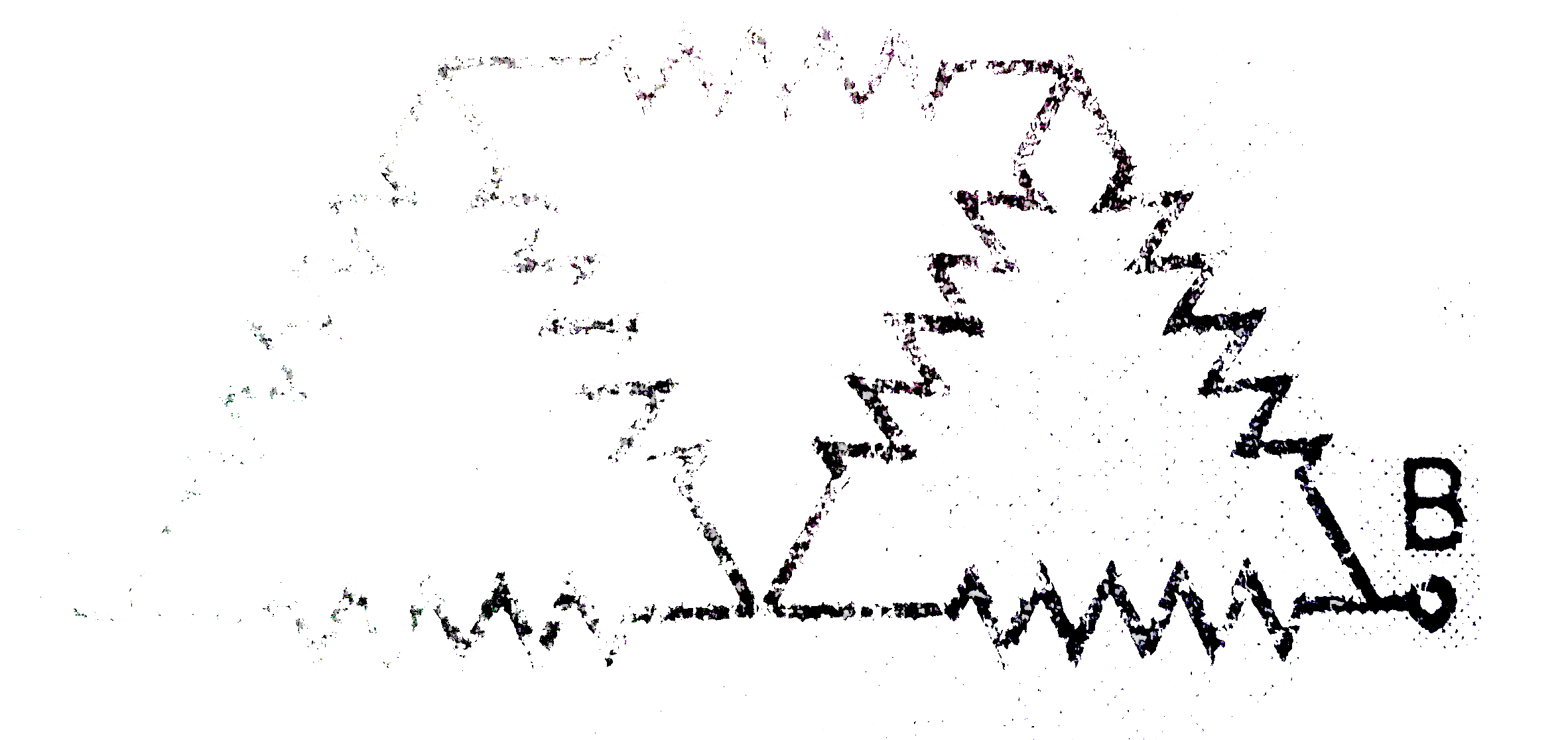
Each resistance is of 1Ω in the circuit diagram shown in figure. Find out equivalent resistance between A and B.
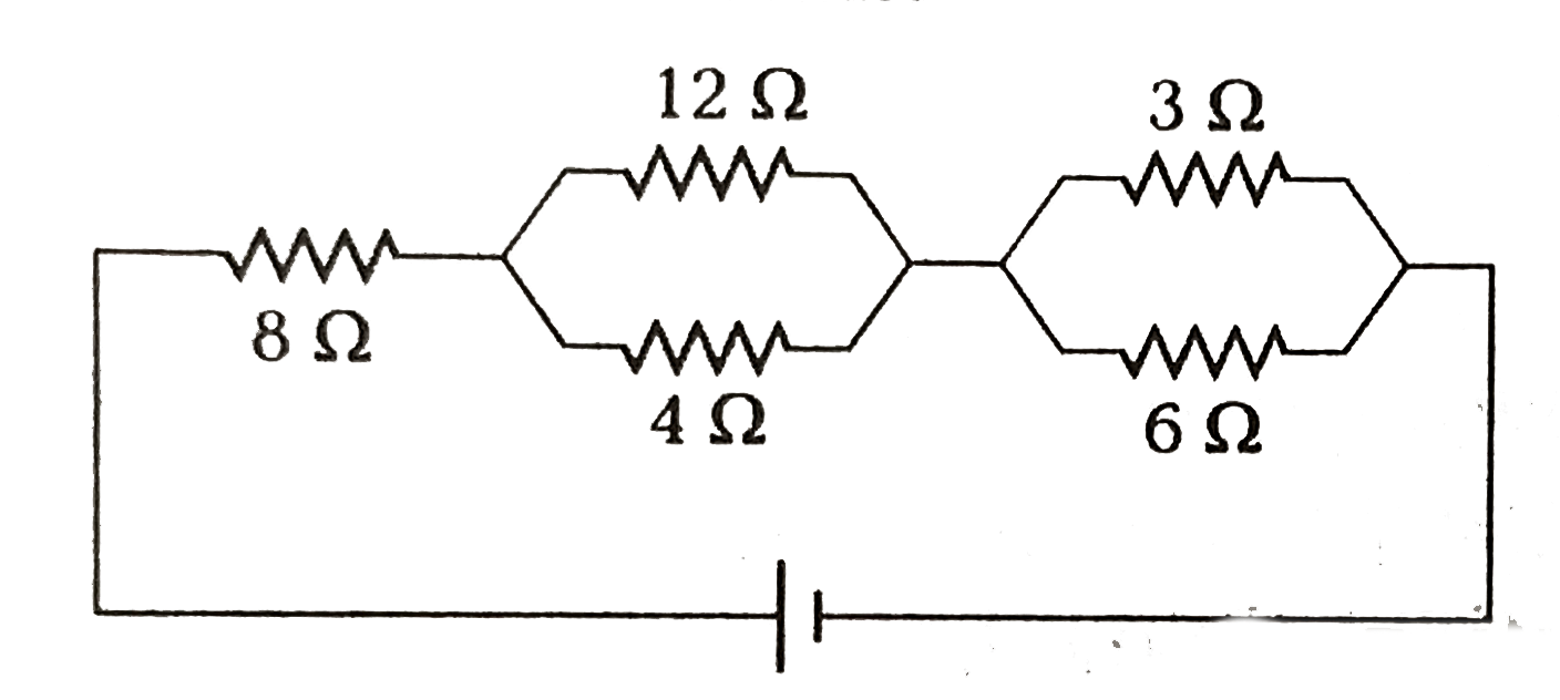
View SolutionIn the circuit diagram shown in figure, potential difference across 3Ω resistance is 20 V. Then, match the following two columns.
View SolutionIn the circuit shown in figure resistance of each wire is r. Net resistance across

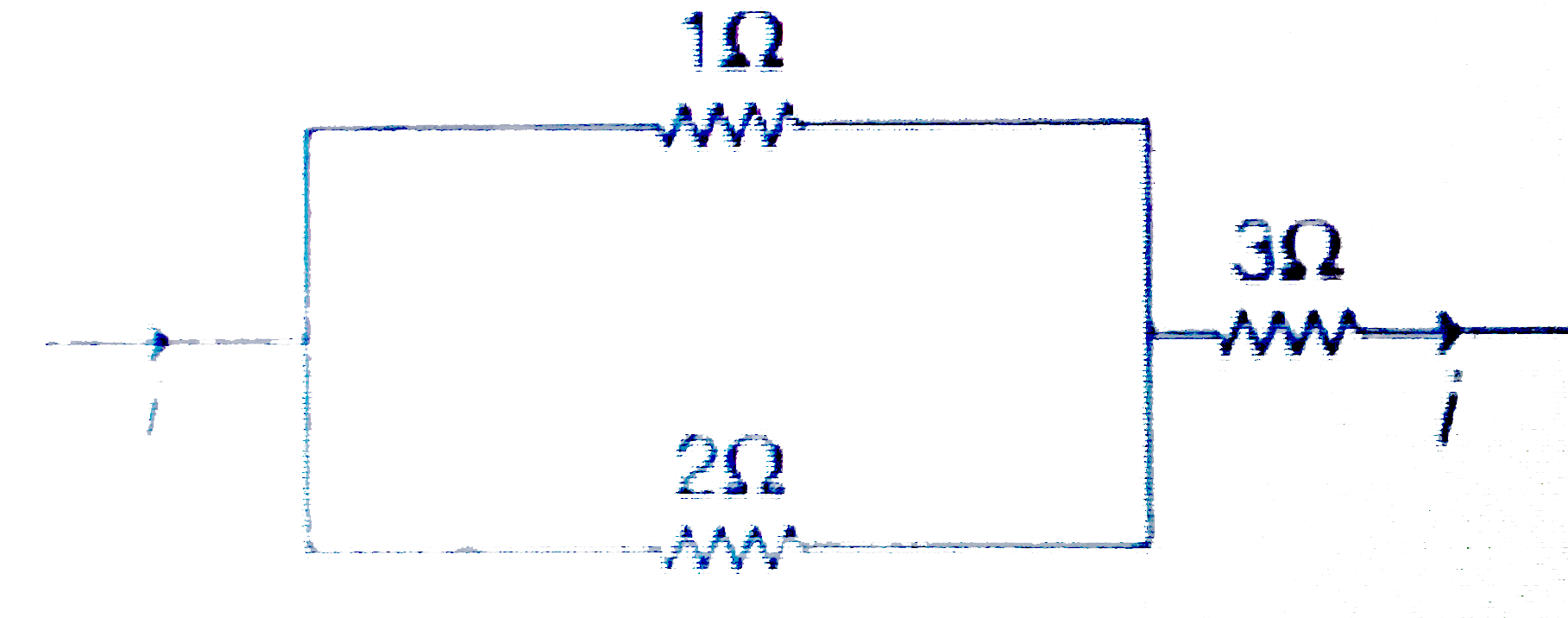
View SolutionIn the circuit shown in figure, power developed across 1Ω,2Ω and 3Ω resistance are in the ratio of
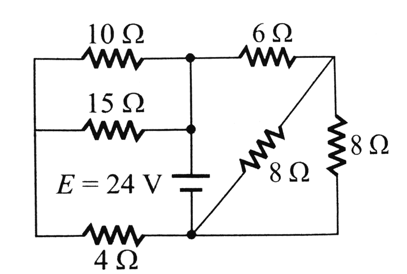
View SolutionThe equivalent resistance across the terminals of source of e.m.f. 24V for the circuit shown in the figure is
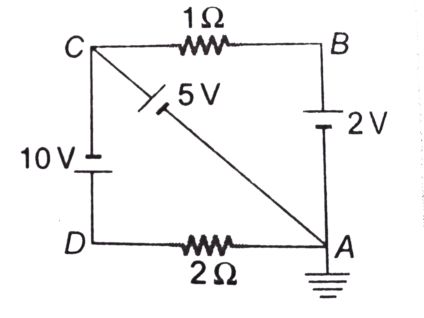
View SolutionIn the circuit shown in figure find the potentials of A,B,C and D and the current through 1Ω and 2Ω resistance.
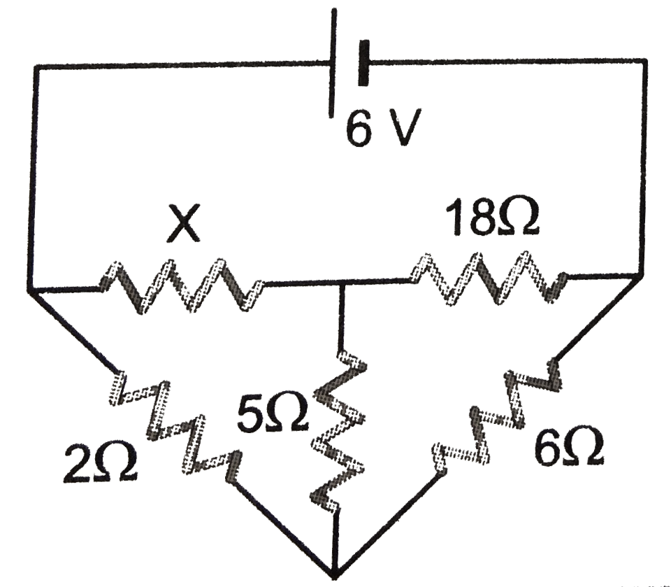
View SolutionFind out the magnitude of resistance X in the circuit shown in figure, When no current flows through the 5Ω resistance
View SolutionAll resistance shown in the circuit are 2Ω each. The current in the resistance between D and E is
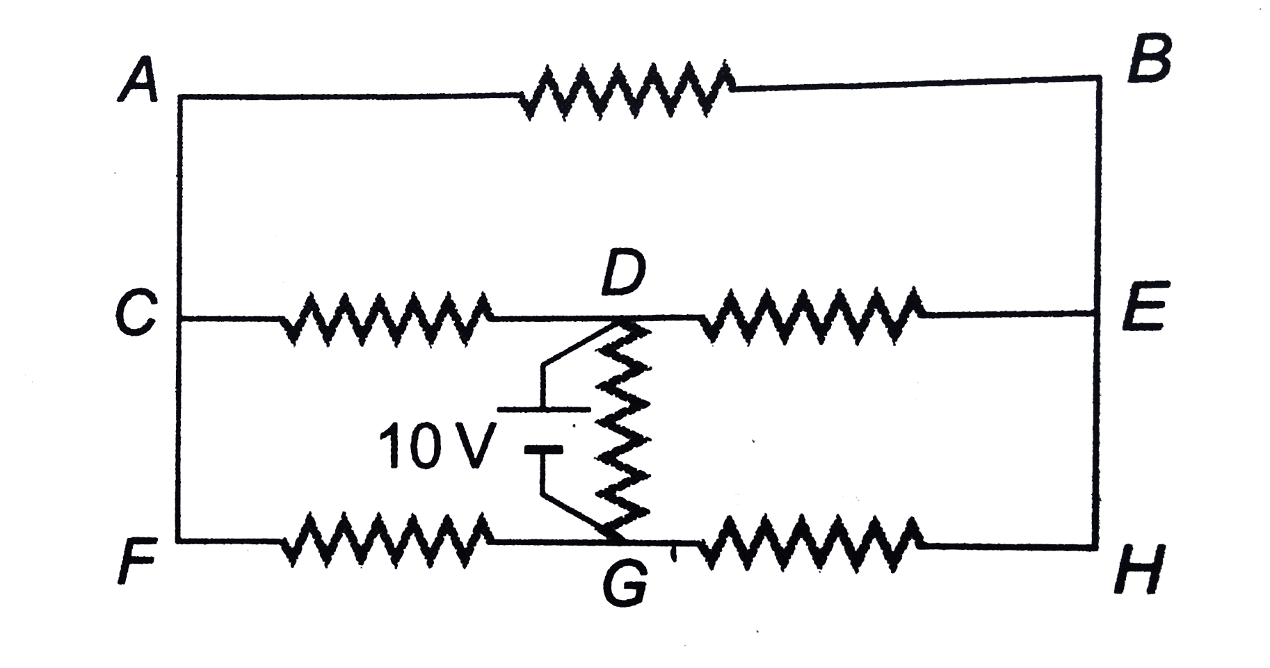
View SolutionAll resistance shown in the circuit are 2Ω each. The current in the resistance between D and E is

View SolutionIn the circuit shown in the figure , the resistance marked R can be varied by using a Rheostat. The power across the 5 Omega resistor will be maximum if the Rhoestat has resistance equal to
_PHY_E01_015_Q01.png)
View Solution
