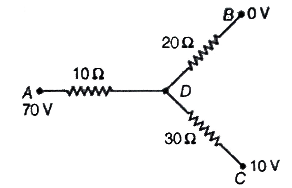
For the network shown below, the value of VB−VA is ______ V
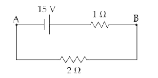
Step by step video & image solution for For the network shown below, the value of V_B-V_A is ______ V by Physics experts to help you in doubts & scoring excellent marks in Class 12 exams.
Updated on:21/07/2023Topper's Solved these Questions
- JEE MAINS 2022BOOK - JEE MAINS PREVIOUS YEARCHAPTER - JEE MAINS 2022EXERCISE - PHYSICS- SECTION A
19 Videos
- JEE MAINS 2022BOOK - JEE MAINS PREVIOUS YEARCHAPTER - JEE MAINS 2022EXERCISE - PHYSICS- SECTION A (ASSERTION (A) REASON (R))
1 Videos
- JEE MAINS 2022BOOK - JEE MAINS PREVIOUS YEARCHAPTER - JEE MAINS 2022EXERCISE - PHYSICS (SECTION -B)
10 Videos
- JEE MAINS 2021BOOK - JEE MAINS PREVIOUS YEARCHAPTER - JEE MAINS 2021EXERCISE - Physics (Section B )
10 Videos
- JEE MAINS 2023 JAN ACTUAL PAPERBOOK - JEE MAINS PREVIOUS YEARCHAPTER - JEE MAINS 2023 JAN ACTUAL PAPEREXERCISE - Question
360 Videos
Similar Questions
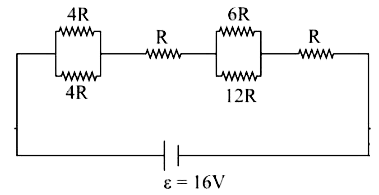
The resistive network shown below is connected to a D.C. source of 16V. The power consumed by the network is 4 Watt. The value of R (in Ω) is _______.
View SolutionFind the effective resistance between points A and B for the network shown in the figure below.
(ARH_NEET_PHY_OBJ_V02_C03_S01_027_Q01.png" width="80%">
View Solution
Knowledge Check
In the network shown below, the equivalent resistance between A and B is
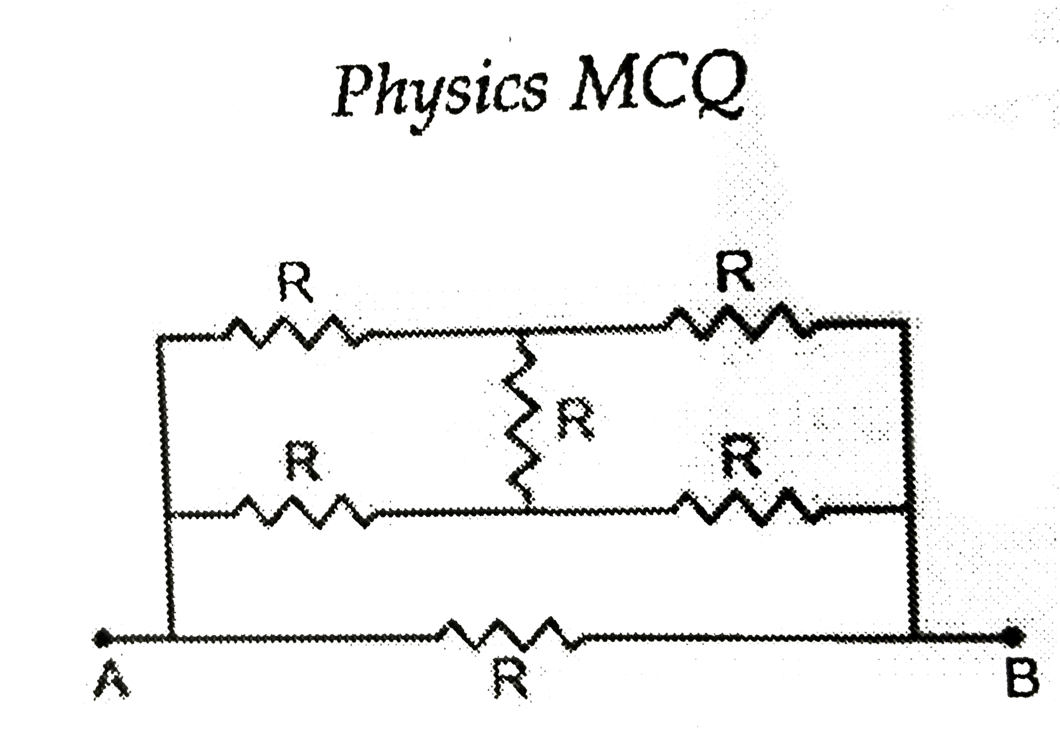 AR/2BRC2RD4R
In P−V diagram shown below,
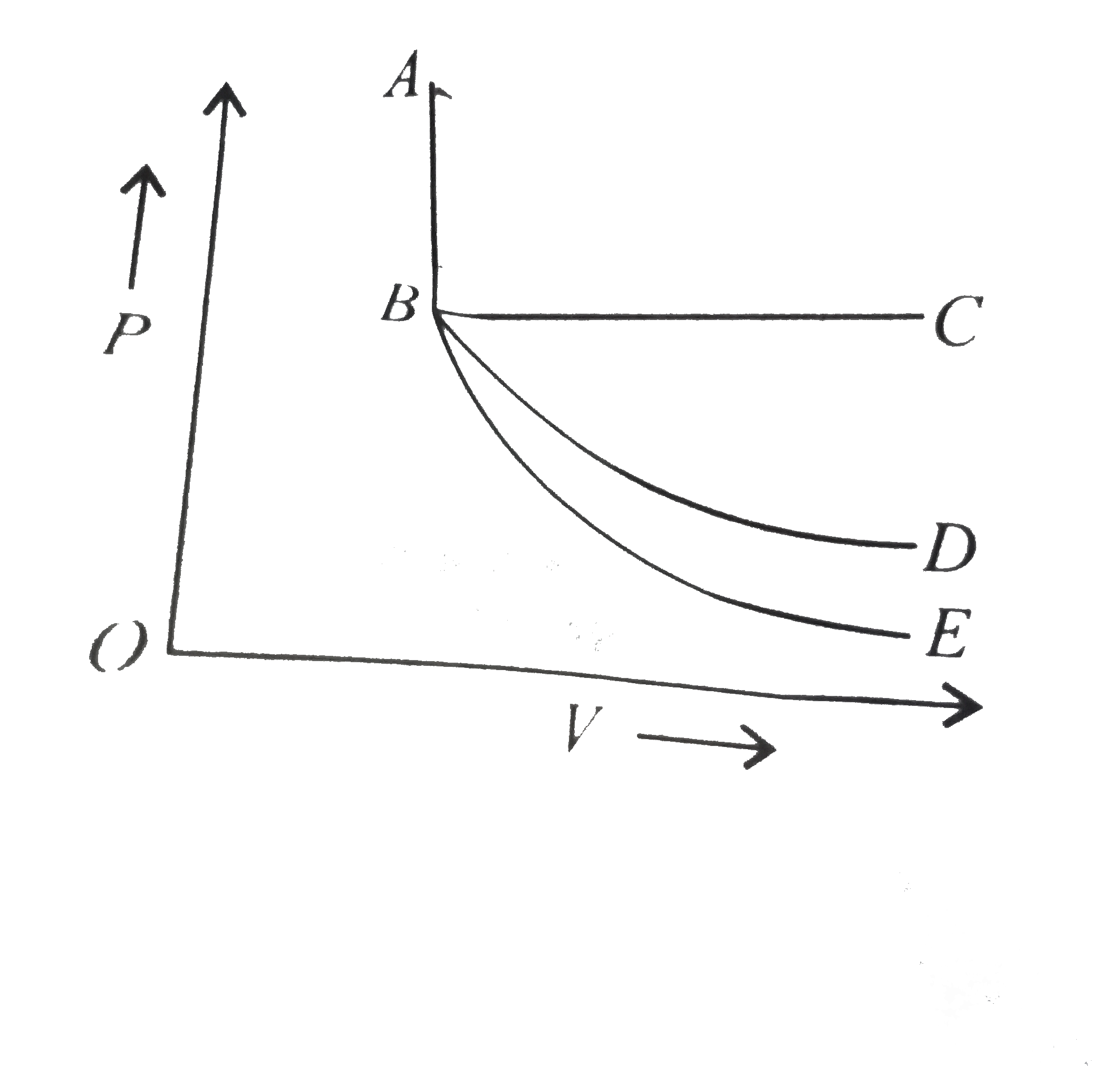 AAB represents adiabatic process.BAB represents isothermal process.CAB represents isobaric process.DAB represents isochoric process.
In the circuit shown the cells A and B have negligible resistance. For VA=12V,R1=500Ω and R=100Ω, the galvanometer (G) shows no deflection. The value of VB is
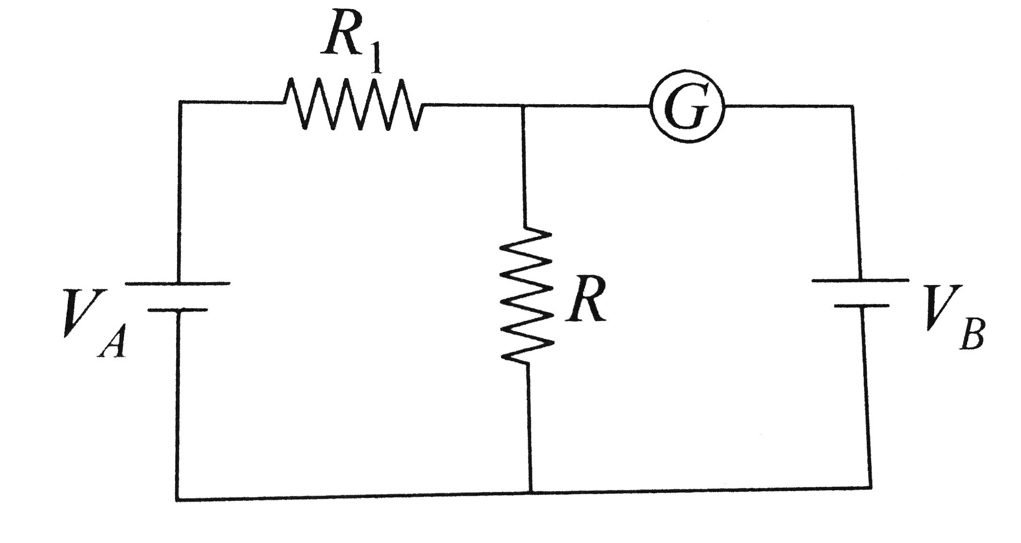 A6VB4VC2VD12V
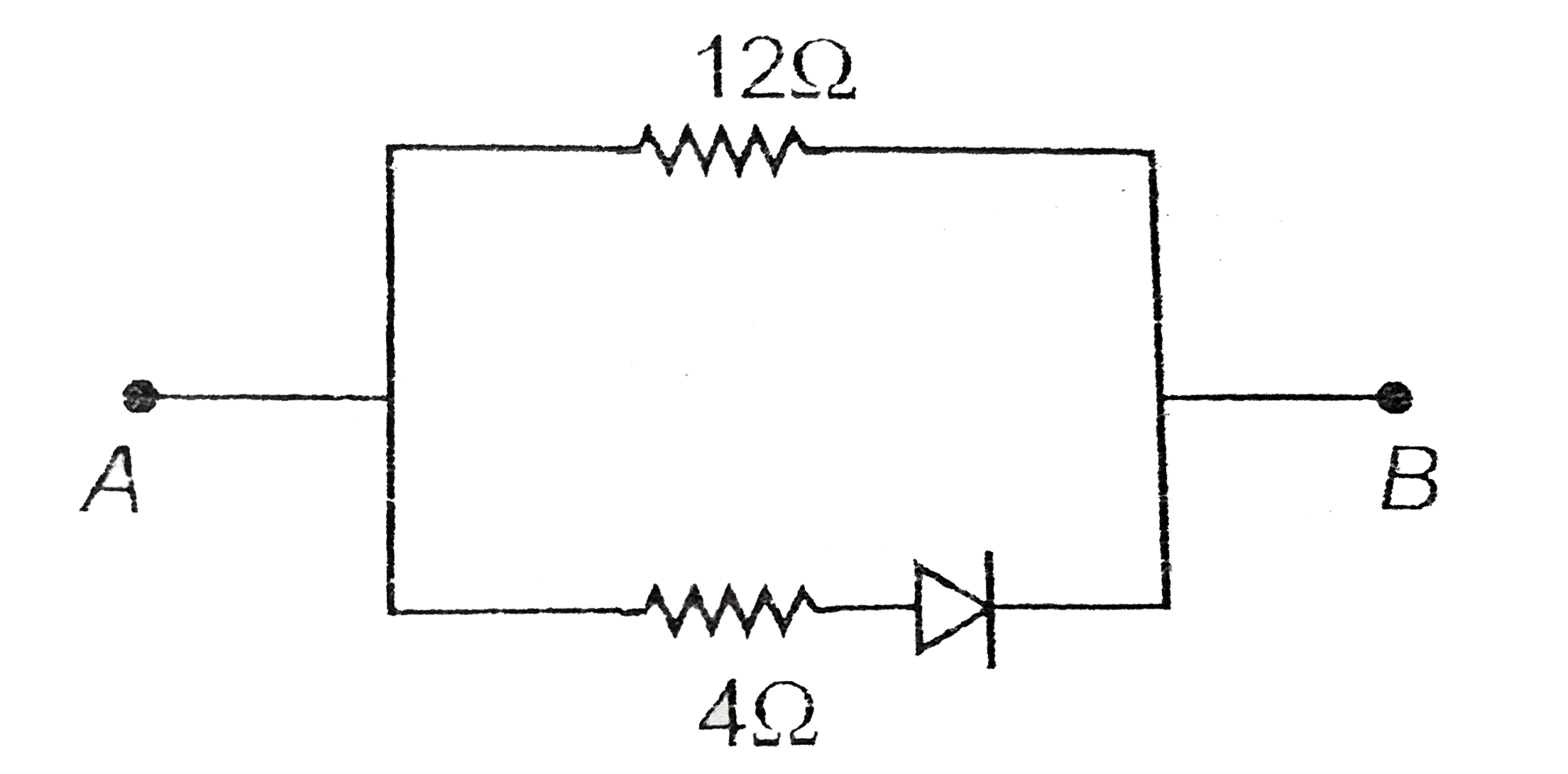
Find the equivalent resistance of the network shown in the figure between the points A and B if
(i) VA>VB (ii) VA<VB
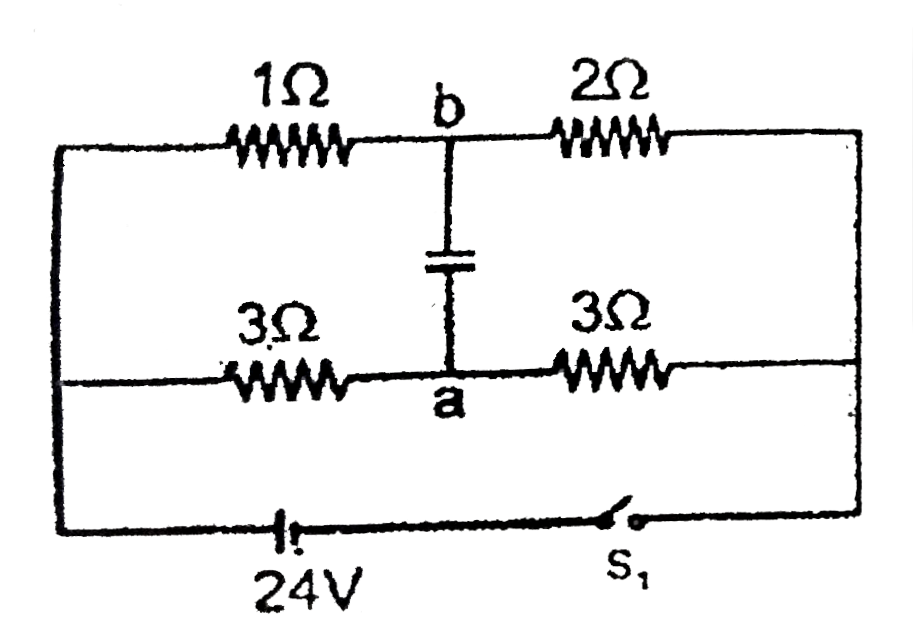
View SolutionFor the circuit shown in the diagram find the value of Va−Vb after long time closing the switch S1:
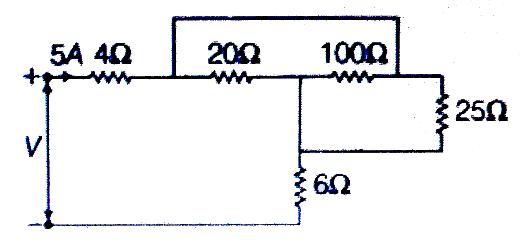
View SolutionIn the circuit shown below, V should be:
View SolutionIn the circuit shown in figure value of VR is
View SolutionFor the network shown in figure, points A, B and C are at potentials of 70 V, zero and 10 V respectively
View Solution
