A source of constant voltage V is connected to a resistance R and two ideal inductor L1andL2 through a switch S as shown. There is no mutual inducance between the two inductors. The swtich S is initially open. At t=0, the switch is closed and current begins to flow. Which of the following options is / are correct ?
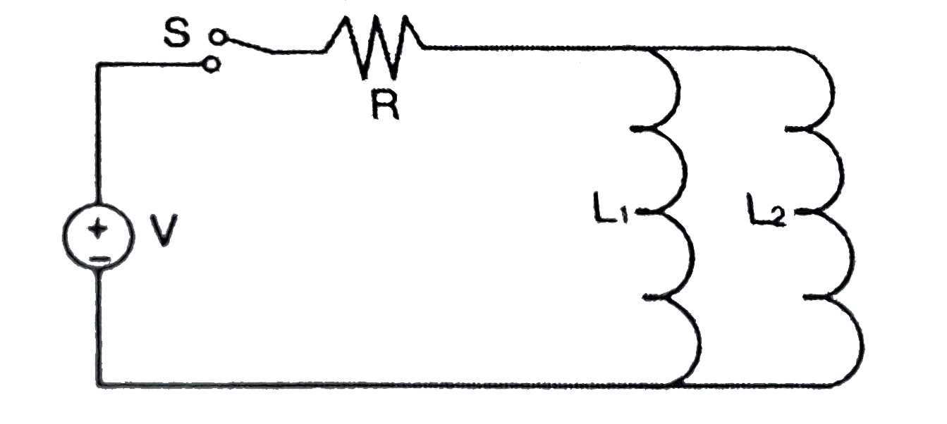
After a long time, the current through L1 will be PRL2L1+L2
After a long time, the current through L2 will be VRL2L1+L2
The ratio of the currents throug L1andL2 is fixes at all times (t>0)
At t=0, the current through the resistance RisQR
The correct Answer is:A, B, C
Step by step video & image solution for A source of constant voltage V is connected to a resistance R and two ideal inductor L_(1) and L_(2) through a switch S as shown. There is no mutual inducance between the two inductors. The swtich S is initially open. At t=0, the switch is closed and current begins to flow. Which of the following options is / are correct ? by Physics experts to help you in doubts & scoring excellent marks in Class 12 exams.
Updated on:21/07/2023Topper's Solved these Questions
- JEE ADVANCEDBOOK - JEE ADVANCED PREVIOUS YEARCHAPTER - JEE ADVANCEDEXERCISE - Part I : PHYSICS (Section 3)Paragraph 2
2 Videos
- JEE ADVANCEDBOOK - JEE ADVANCED PREVIOUS YEARCHAPTER - JEE ADVANCEDEXERCISE - SECTION 1
6 Videos
- JEE ADVANCEDBOOK - JEE ADVANCED PREVIOUS YEARCHAPTER - JEE ADVANCEDEXERCISE - PART I : PHYSICS (SECTION 3)
2 Videos
- JEE (ADVANCE) 2020BOOK - JEE ADVANCED PREVIOUS YEARCHAPTER - JEE (ADVANCE) 2020EXERCISE - SECTION 3
6 Videos
- JEE ADVANCED 2020BOOK - JEE ADVANCED PREVIOUS YEARCHAPTER - JEE ADVANCED 2020EXERCISE - SECTION-3
6 Videos
Similar Questions
shows three resistances are
connected with switch S initially the switch is open. When
the switch S is closed find the current passed through it.
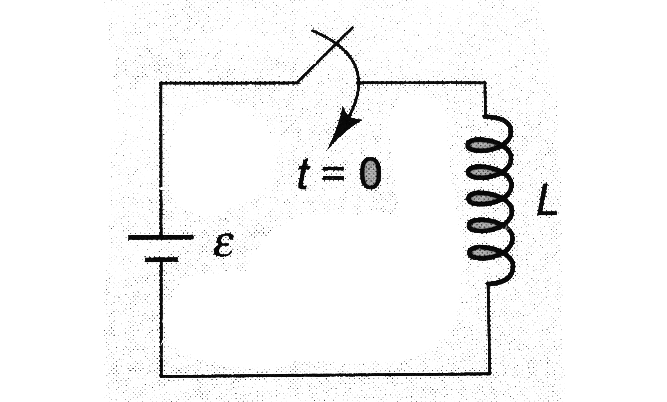
View SolutionA circuit contains an ideal cell and an inductor with a switch. Initially, the switch is open. It is closed at t=0. Find the current as a function of time.
View Solution
Knowledge Check
A capacitor is charged to a potential of V0. It is connected with an inductor through a switch S. The switch is closed at time t=0. Which of the following statement(s) is/are correct?
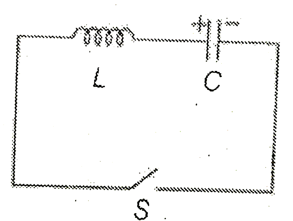 AThe maximum current in the circuit is V0√CLBPotential across capacitor becomes zero for the first time at t=π√LCCEnergy stored in the inductor at time t=π2√LC is 14CV20DMaximum energy stored in the inductor 12CV20
A light bulb, a capacitor and a battery are connected together as shown here, with switch S initially open. When the switch S is closed, then which one of the following is true
 Athe bulb will light up for an instant when the capacitor starts chargingBthe bulb will light up when the capacitor is fully chargedCthe bulb will not light up at allDthe bulb will light up and go off at regular intervals
In the circuit, a battery of emf E, a resistance R and inductance coil L1andL2 and switch S are connected as shown. In Fig. Initially the switch is open
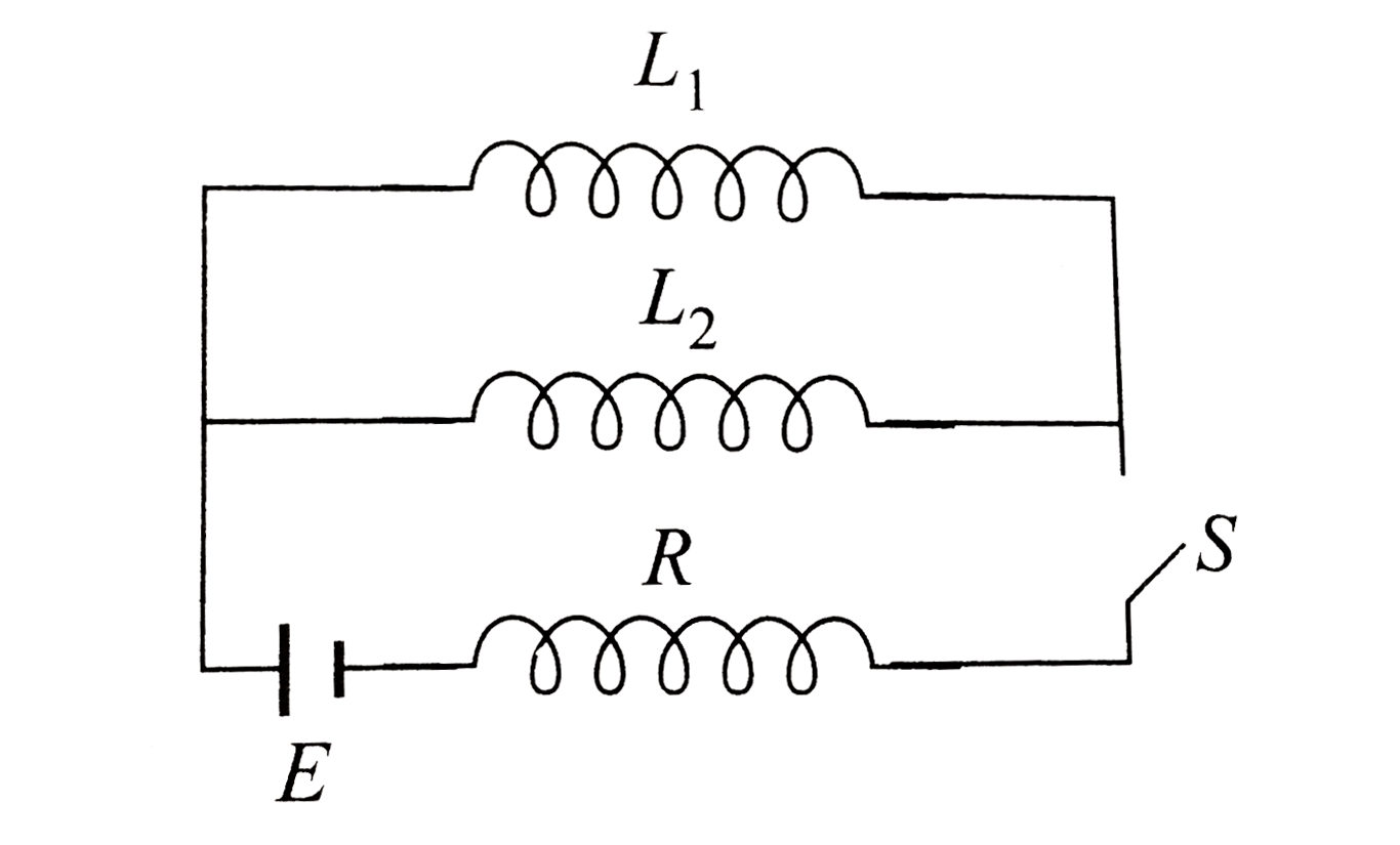 AThe time constant of the circuit is 1RL1L2L1+L2BSteady state current in the inductor L1is(EL_(2))/(R(L_(1)+L_(2)))CSteady state current in the inductor L2 is EL1R(L1+L2)DIn steady the total energy stored in the inductor coils is 12L1L2L1+L2E2R2
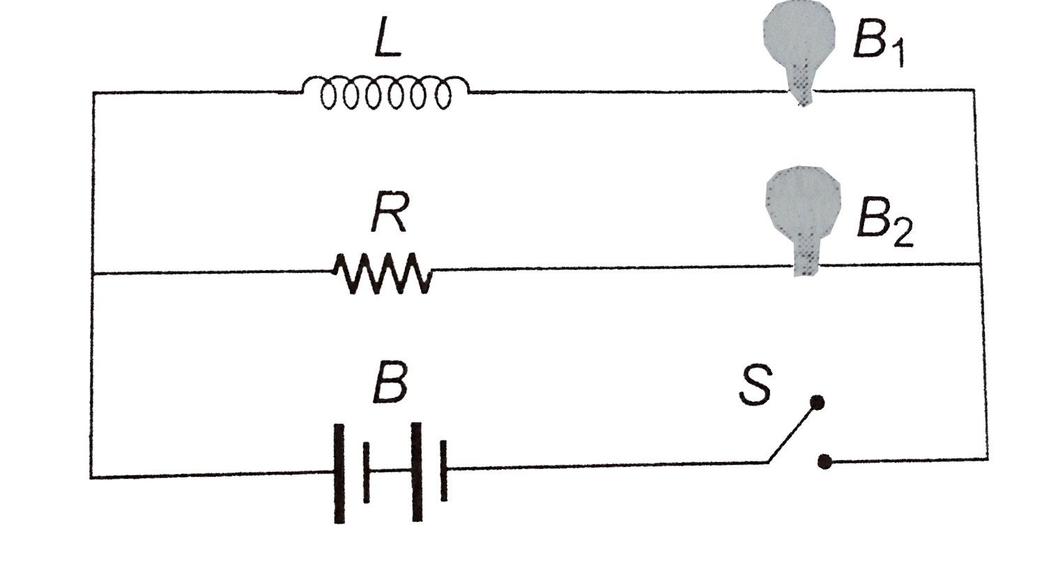
An inductor L , a resistanece R and two identical bulbs, B1 and B2 are connected to a battery through a switch S as shown in the figure. The resistance R is the samem as that of the coil that makes L .Which of the following statement gives the correct description of the happenings when the switch S is closed
View SolutionSwitch S of the circuit shows in Fig is closed at t=0. If e denotes the induced emf in L and I is the current flowing through the circuit the circuit at time t, which of the following graphs is//are correct?

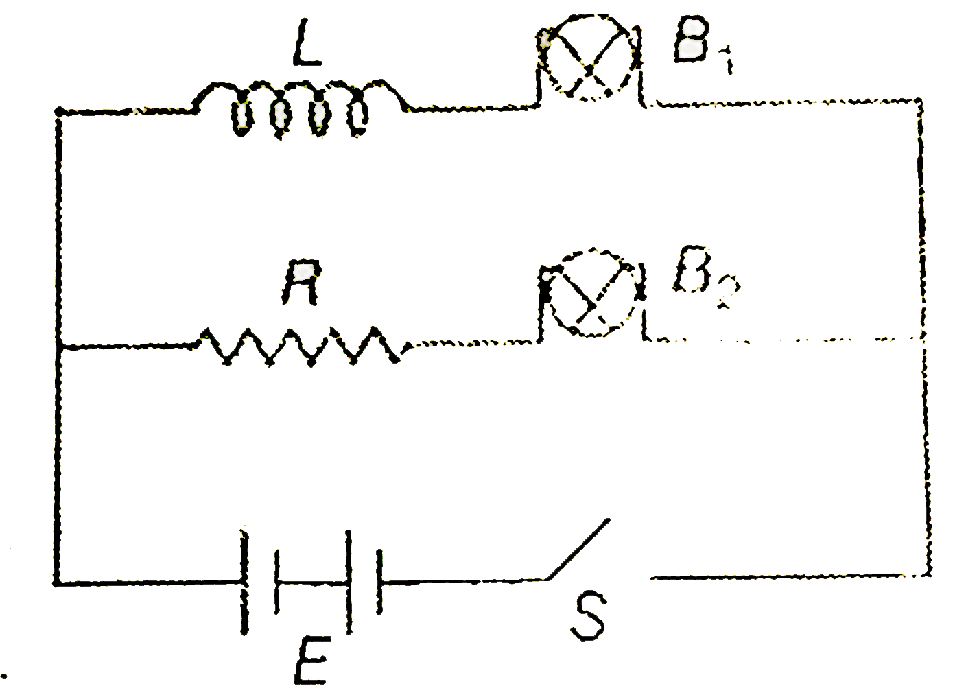
View SolutionAn inductor L, a resistanc eR and two identical bulbs B1andB2 are connected to a battery through a switch S as shown in the figure . The resistance of coil having inductance L is also R. Which of the following statement gives the corrrect description of the happenings when the switch S is closed?
View SolutionConsider a circuit consists of resistors, inductor, battery and a switch as shown. Resistance of resistors, inductance of inductor and EMF of battery are indicated. The switch is closed at t=0.
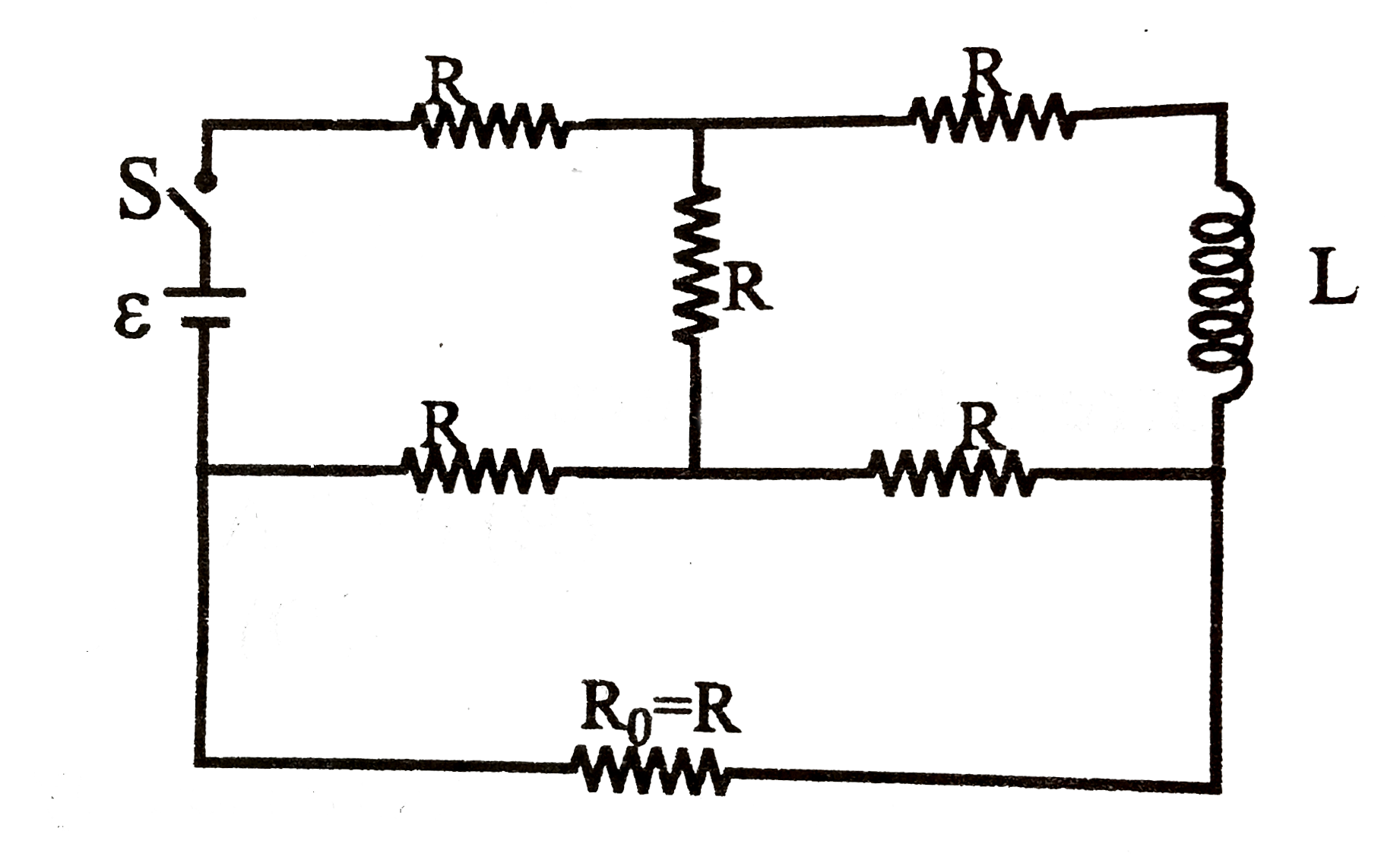
Find current through at steady state
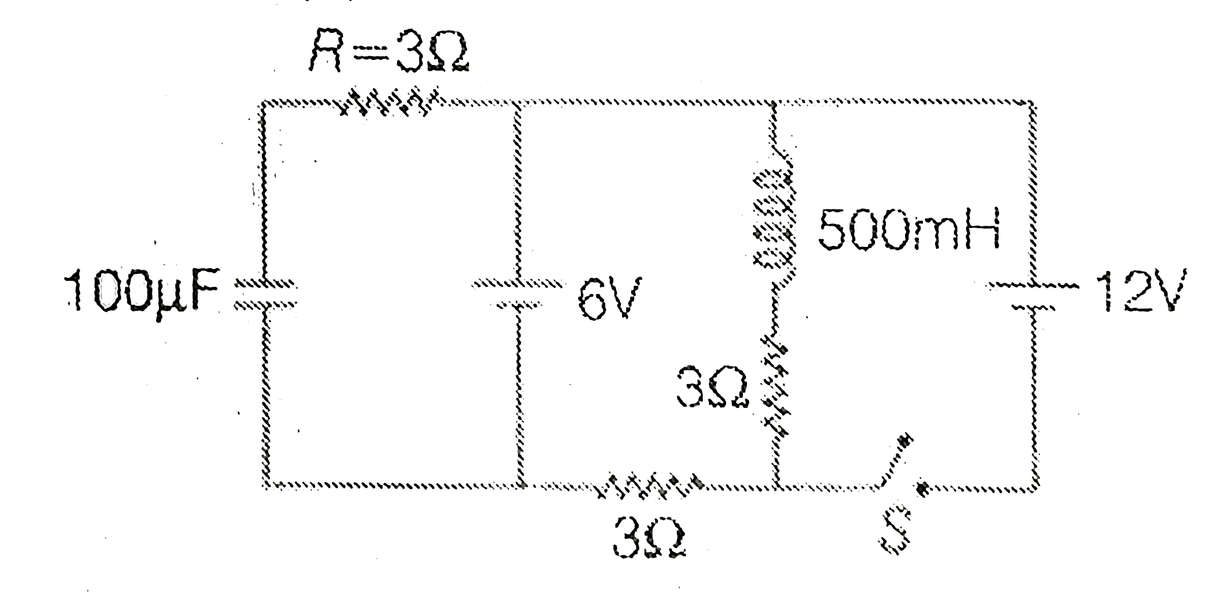
View SolutionIn the circuit diagram shown in figure, initially switch S is opened and the circuit is in steady state. At time t=0, the switch S is closed and the new steady state is reached after some time. Choose the correct option(s)
View Solution
