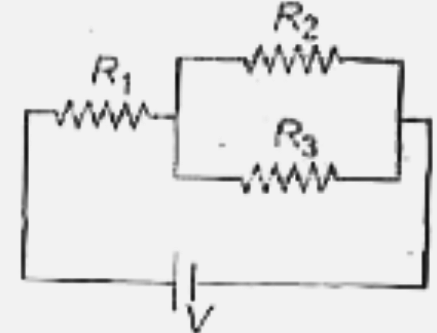
For ensuring dissipation of same energy in all three resistors (R1,R2,R3) connected as shown in figure, their values must be related as

R1=R2−R3
R2=R3andR1=4R2
R2=R3andR1=14R2
R1=R2+R3
The correct Answer is:C
Step by step video & image solution for For ensuring dissipation of same energy in all three resistors (R_(1), R_(2), R_(3)) connected as shown in figure, their values must be related as by Physics experts to help you in doubts & scoring excellent marks in Class 12 exams.
Topper's Solved these Questions
- BOOK - CENGAGE PHYSICS ENGLISHCHAPTER - HEATING EFFECT OF CURRENTEXERCISE - Calculating Thermal Power in Resistance14videos
HEATING EFFECT OF CURRENT
- BOOK - CENGAGE PHYSICS ENGLISHCHAPTER - GEOMETRICAL OPTICSEXERCISE - Integer Type4videos
GEOMETRICAL OPTICS
- BOOK - CENGAGE PHYSICS ENGLISHCHAPTER - INDUCTANCEEXERCISE - Concept Based8videos
INDUCTANCE
Similar Questions
For ensuring dissipation of same energy in all three resistors (R1,R2,R3) connected as shown in figure, their values must be related s
 View Solution
Three identical resistors R1=R2=R3 are connected as shown to a battery of constant e.m.f . The power dissipated is
 View Solution
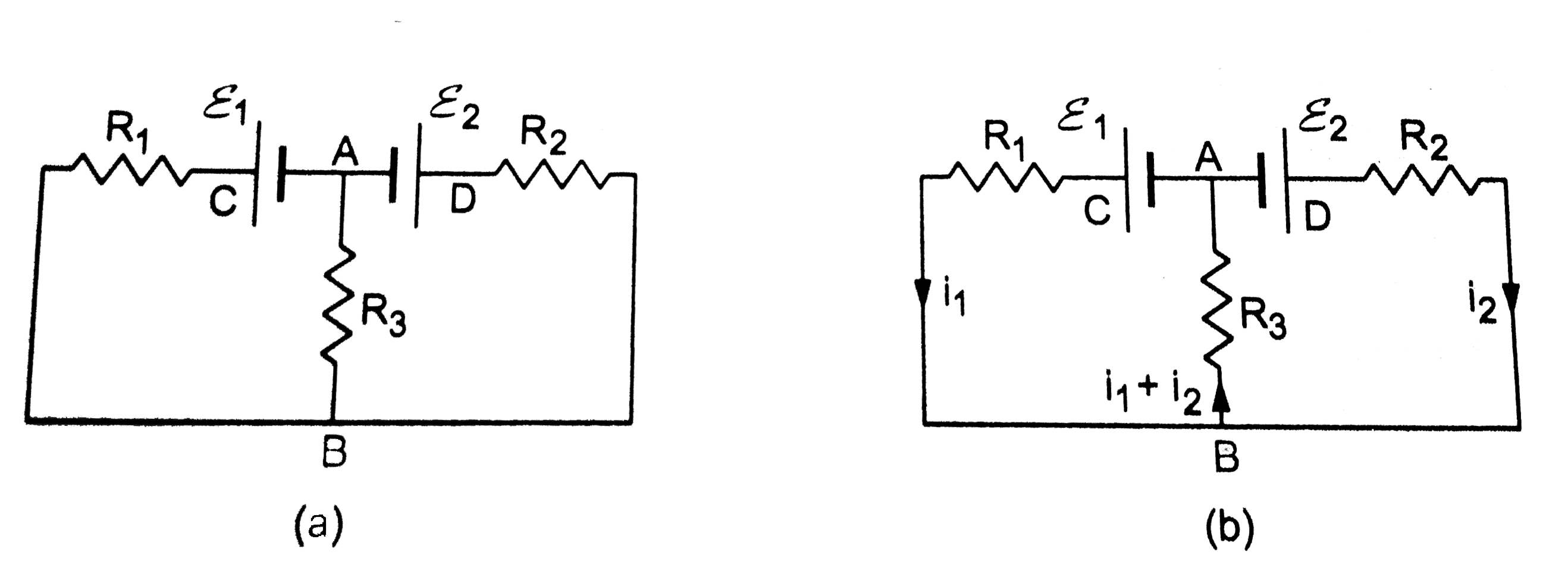
Find the currents going through the three resistors R1,R2 and R3 in the circuit of figure.
 View Solution
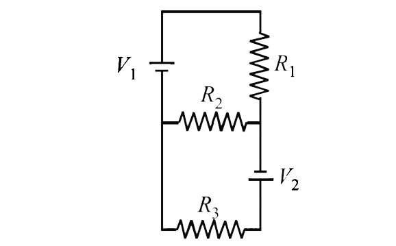
Two ideal batteries of emf V1andV2 and three resistances R1,R2andR3 are connected as shown in the figure. The current in resistance R2 would be zero if
 View Solution
The current in the resistor R3 in the circuit as shown in the figure is
 View Solution
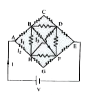
Fourteen identical resistors, each of resistance r each connected as shown in figure. Pick the incorrect alternative(s)
 View Solution
Idnetical resistor each of resistance r are connected as shown in figure. Calculate equivalent resistance between A and E.
 View Solution
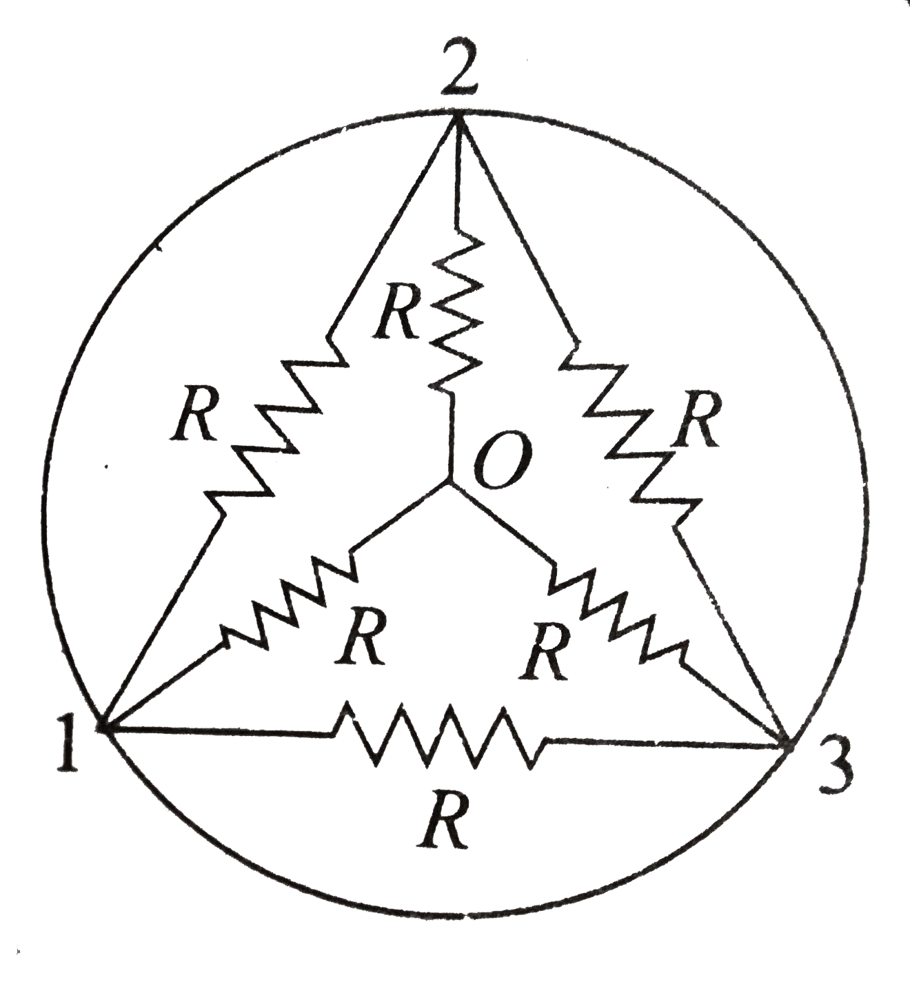
Inside a supeerconducting ring, six identical resistors each of resistance R are connected as shown in figure. The equivalent resistances.
 View Solution
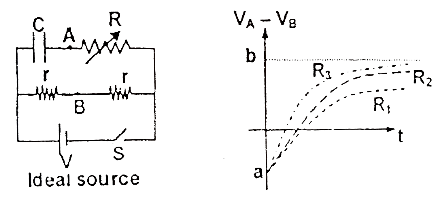
An uncharged capacitor C and a variable resistance R are connected to an ideal source and two resistors with the help of a switch at t=0 as shown in the figure. Initially capacitor is uncharged and switch S is closed at t=0sec. The graph between VA−VB for variable Resistor R for its three different values R1, R2, and R3 versus time is shown in the figure II. Choose the correct statement
 View Solution
The power dissipated in the resistance R, in the circuit as shown in the figure, is maximum if R is equal to
View Solution

