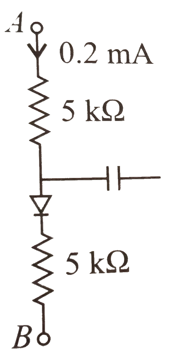
In the circuit shown in figure, if the diode forward voltage drop is 0.3 V, then the voltage difference between A to B is,

1.3V
2.3V
0
0.5V
The correct Answer is:B
Consider the fig. (b) given here, suppose the potential difference between A and B r1=5kΩ and r2=5kΩ are resistance in series connection.
Then, V−03=[(r1+r2)103]×(0.2×10−3)]
=[(5+5)103]×(0.2×10−3)
=10×103×0.2×10−3=2
⇒V=2+0.3=2.3V
Topper's Solved these Questions
- BOOK - NCERT EXEMPLAR ENGLISHCHAPTER - NUCLEIEXERCISE - Very short Anwer type question14videos
NUCLEI
- BOOK - NCERT EXEMPLAR ENGLISHCHAPTER - NUCLEIEXERCISE - Long answer type question10videos
NUCLEI
- BOOK - NCERT EXEMPLAR ENGLISHCHAPTER - MOVING CHARNGES AND MAGNETISMEXERCISE - Long Answer Type Questions7videos
MOVING CHARNGES AND MAGNETISM
- BOOK - NCERT EXEMPLAR ENGLISHCHAPTER - RAY OPTICS AND OPTICAL INSTRUMENTS EXERCISE - VERY SHORT ANSWER TYPE QUESTIONS16videos
RAY OPTICS AND OPTICAL INSTRUMENTS
Similar Questions
Knowledge Check
- Question 1 - Select One
In the circuit shown in figure, if the A diode forward voltage drop is 0.3 V, the voltage difference between A and B is
 A1.3 VB2.3 VC0D0.5 V
 - Question 2 - Select One
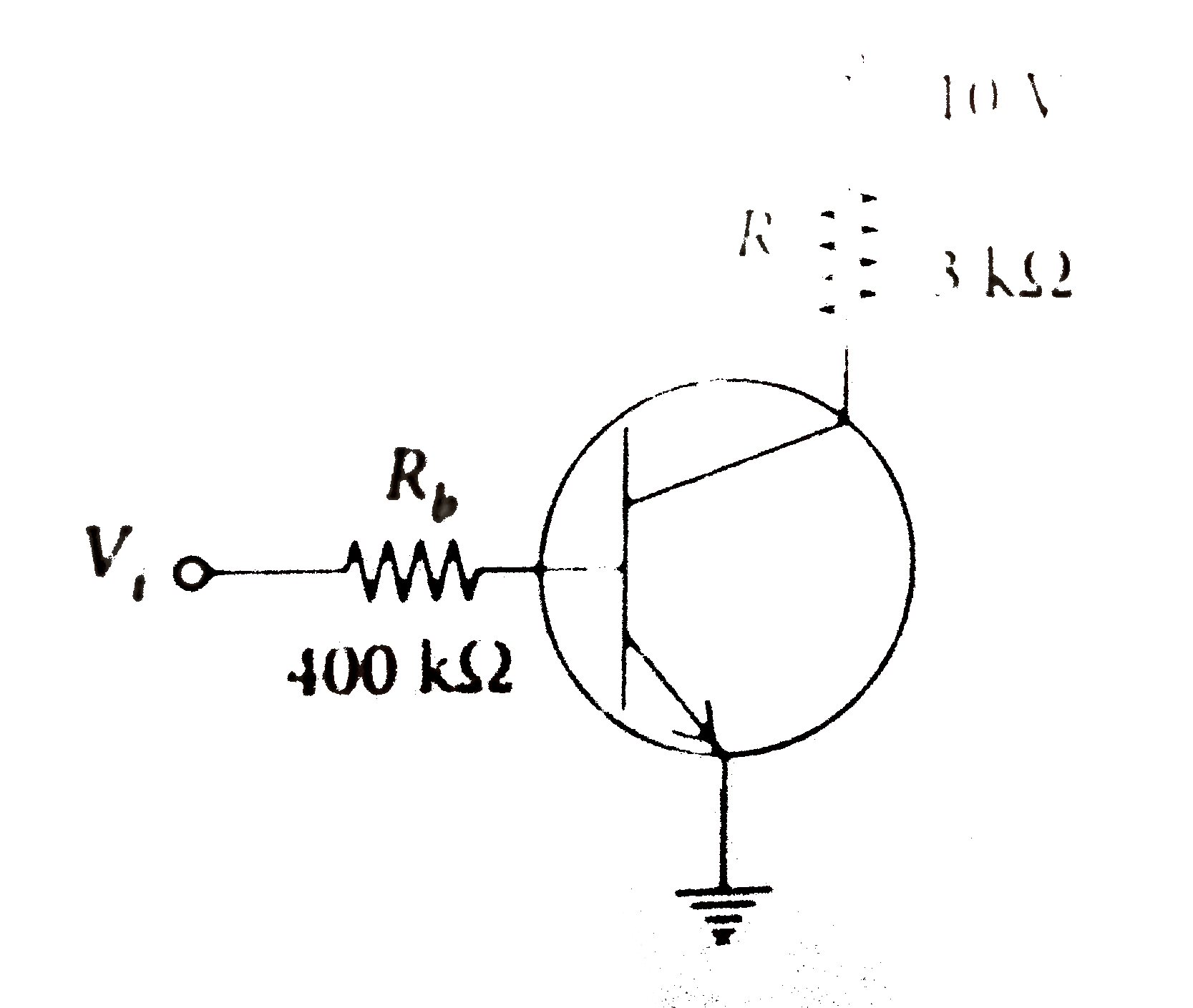
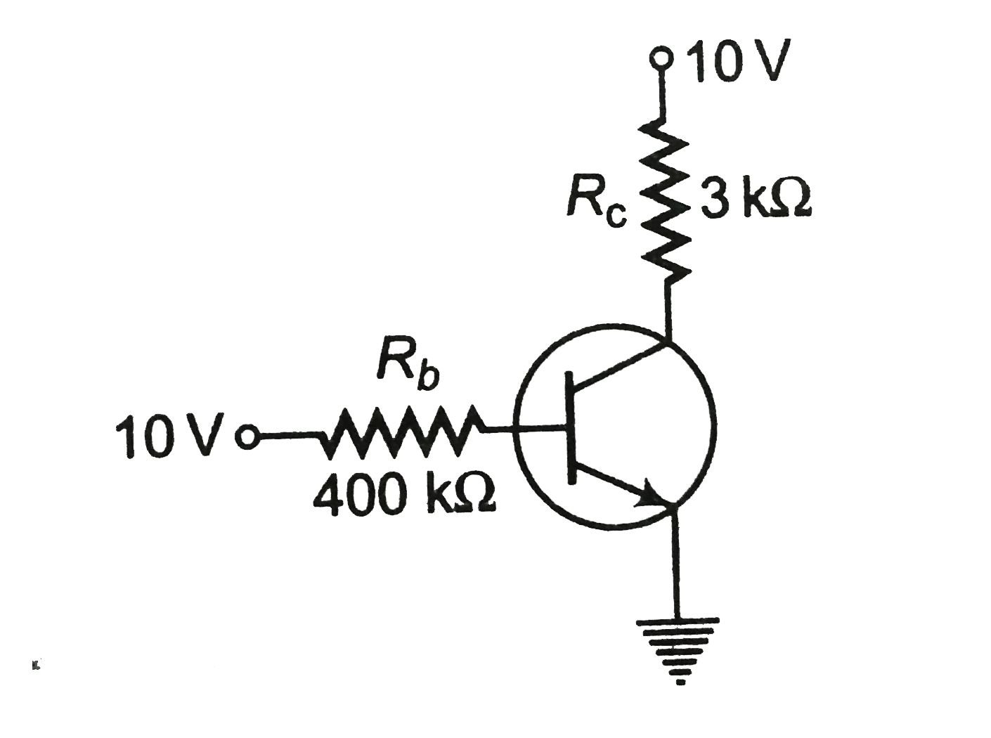
In the circuit shown in figure, when the input voltage of the base resistance is 10 V, Vbe is zero and Vce is also zero. Then
 Aβ=110BIb=25μACIc=3.33mADboth (A) and (C )
 - Question 3 - Select One
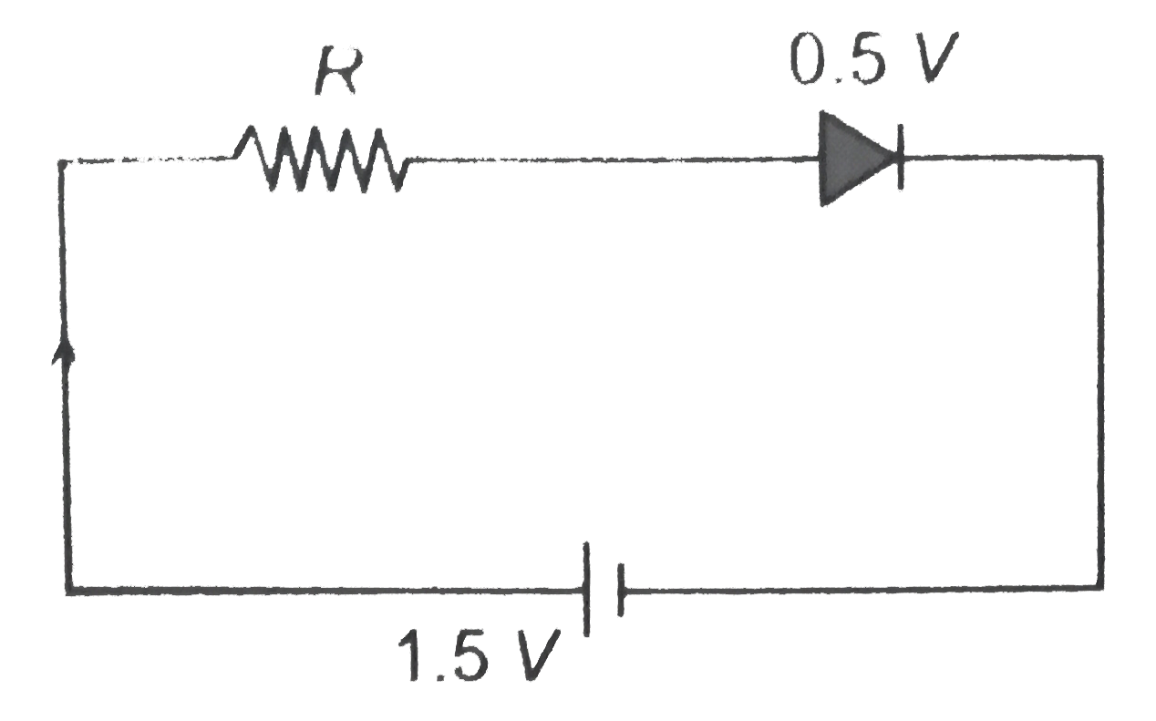
The diode used in the circuit shown in the figure has a constant voltage drop of 0.5V at all currents and a maximum power rating fo 100 milliwatts. What should be the value of the resistor R, connected in series with the diode for obtaining maximum current?
 A6.76ΩB20ΩC5ΩD5.6Ω
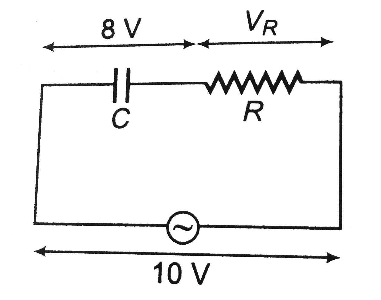
In a series C−R circuit shown in figureure, the applied voltage is 10V and the voltage across capacitor is found to8V. The voltage across R, and the phase difference between current and the applied voltage will respectively be
 .View Solution
In a series C−R circuit shown in figureure, the applied voltage is 10V and the voltage across capacitor is found to8V. The voltage across R, and the phase difference between current and the applied voltage will respectively be
 .View Solution
If the forward voltage in a diode is increased, the width of the depletion region-
View SolutionThe diode used in the circuit shown in the figure has a constant voltage drop of 1V at all current and a maximum power rating of 100mW. What should be the value of the resistor R, connected in series with the diode for obtaining maximum current put less l?
 View Solution
In the circuit shown in figure when the input voltage of the base resistance is 10 V . Find the values of Ib,Icandβ .
 View Solution


