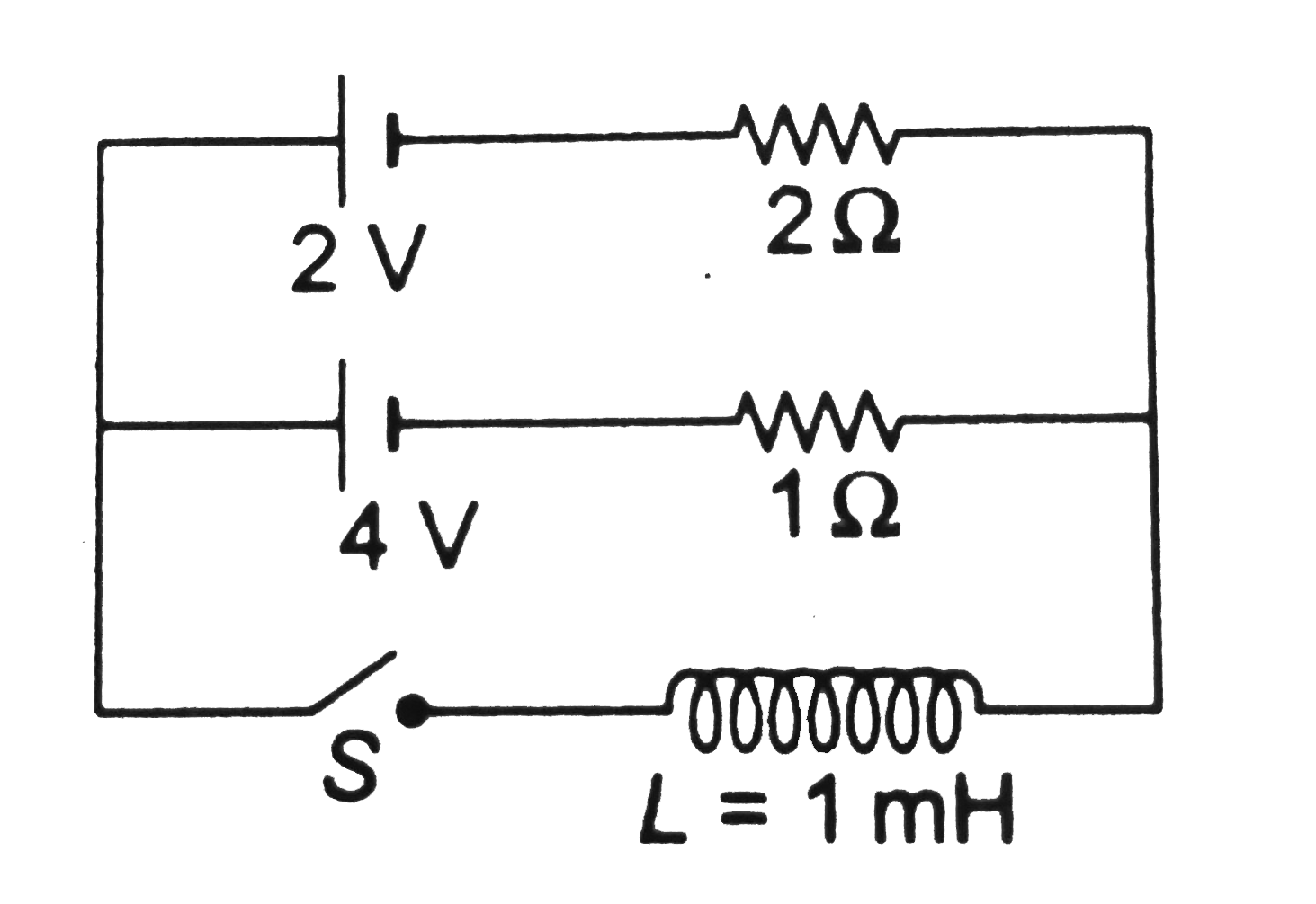
In the circuit shown, switch S is closed at time t=0. Find the current through the inductor as a function of time t.
The correct Answer is:A, B, C
At t=0, Current through inductor will be zero.
At t=∞ net emf =2/2+4/11/2+1/1=103V
Net resistance =2×12+1=23Ω
∴i=10/32/3=5A
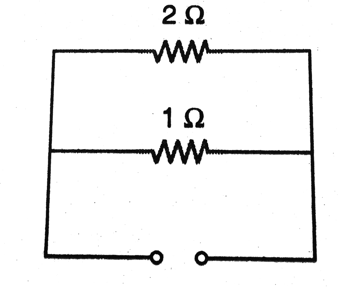
To find equivalent time constant short circuit, both the batteries and find net resistance across inductor.
Rnet=2×12+1=23Ω
∴τL=LRnet=1×10−323=32000s
Current through inductor will increase exponentially from 0 to 5 A.
∴i=5(1−e−2000t3)
Topper's Solved these Questions
- ELECTROMAGNETIC INDUCTIONBOOK - DC PANDEYCHAPTER - ELECTROMAGNETIC INDUCTIONEXERCISE - Check point
60 Videos
- ELECTROMAGNETIC INDUCTIONBOOK - DC PANDEYCHAPTER - ELECTROMAGNETIC INDUCTIONEXERCISE - Taking it together
119 Videos
- ELECTROMAGNETIC INDUCTIONBOOK - DC PANDEYCHAPTER - ELECTROMAGNETIC INDUCTIONEXERCISE - SUBJECTIVE TYPE
1 Videos
- CURRENT ELECTRICITYBOOK - DC PANDEYCHAPTER - CURRENT ELECTRICITYEXERCISE - Medical entrances gallery
97 Videos
- ELECTROMAGNETIC WAVESBOOK - DC PANDEYCHAPTER - ELECTROMAGNETIC WAVESEXERCISE - Sec C
22 Videos
Similar Questions
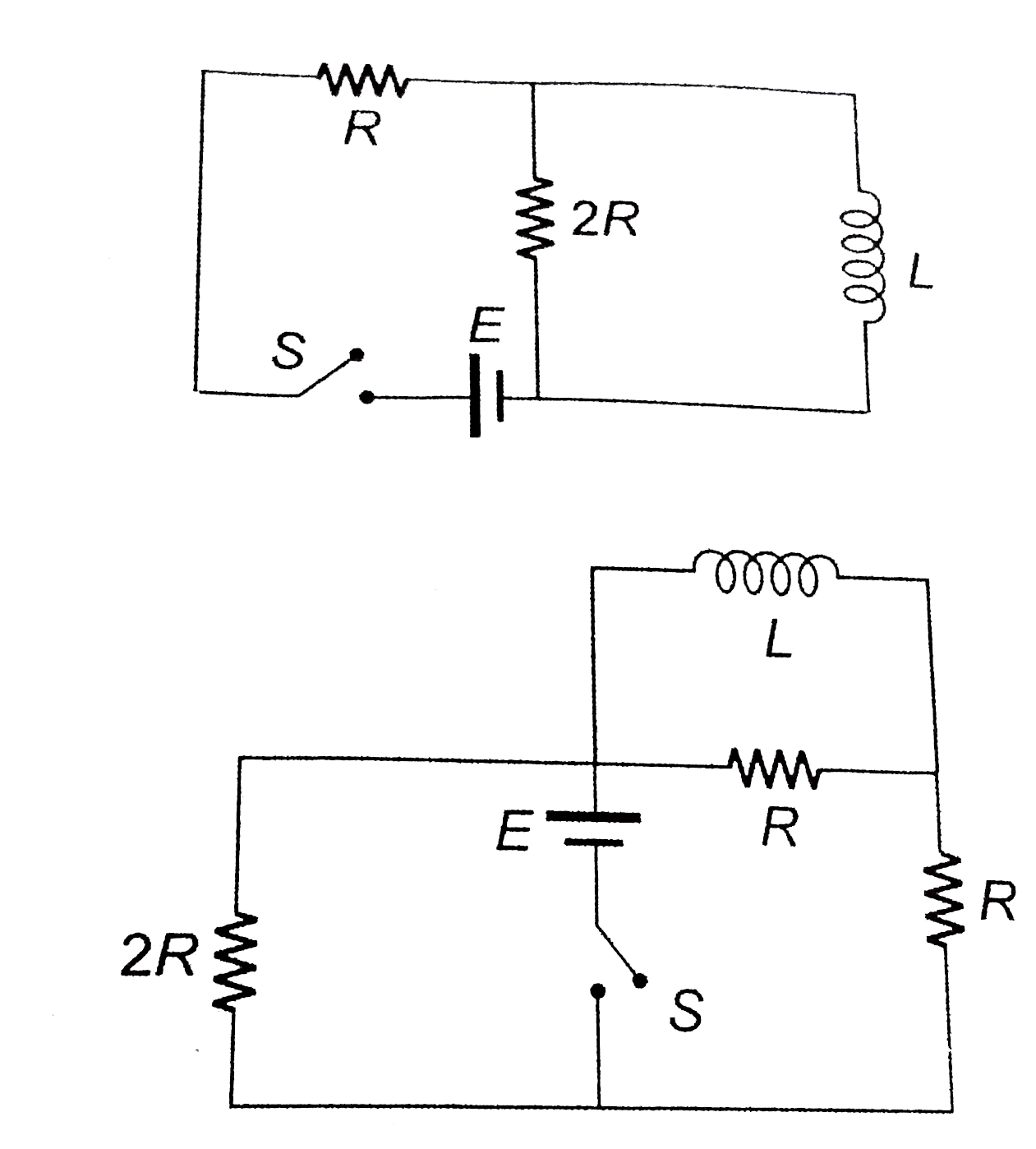
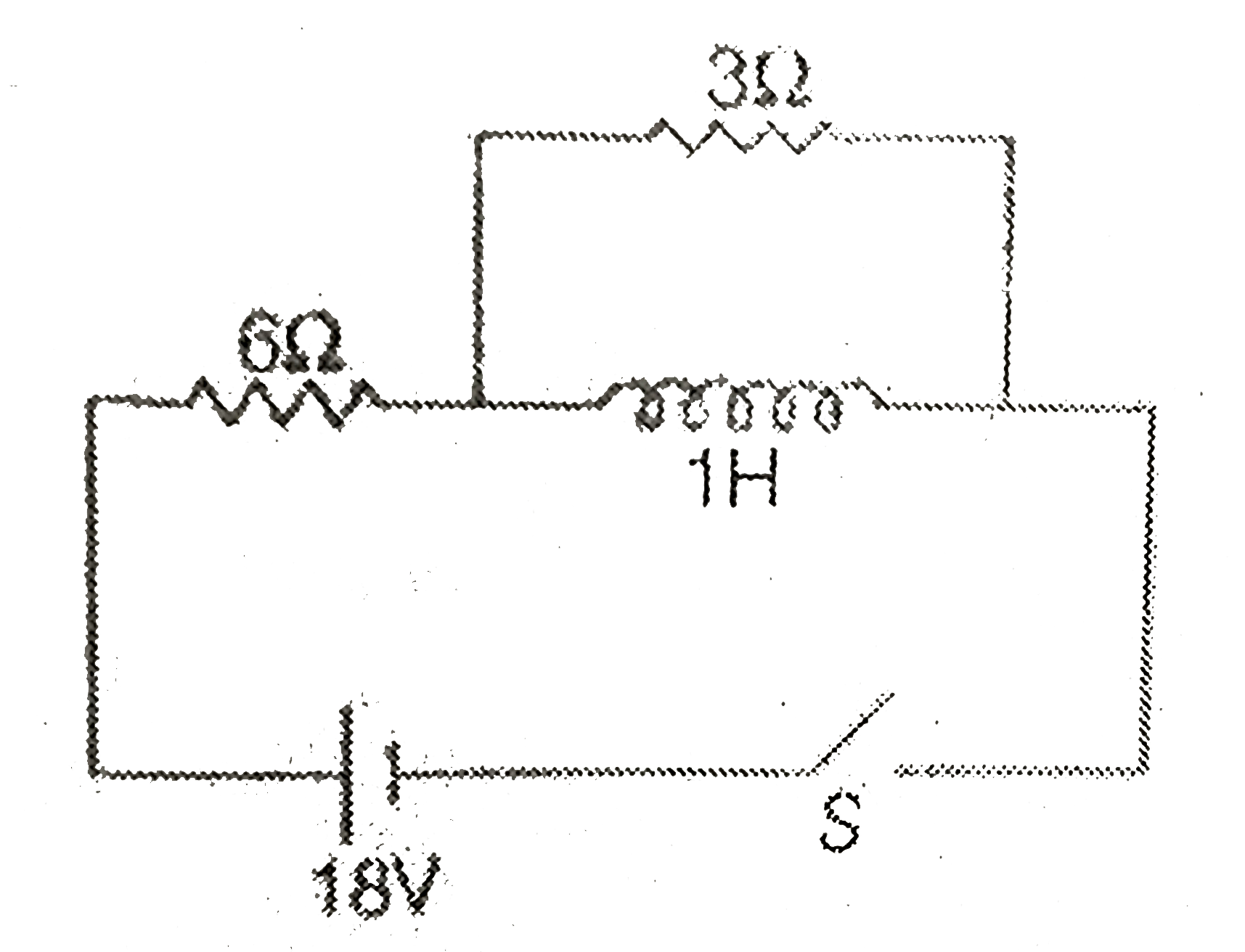
At t=0 , switch S is closed. Find time constant of the circuit and current through inductor as a function of time t .
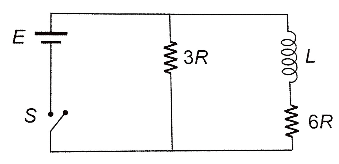
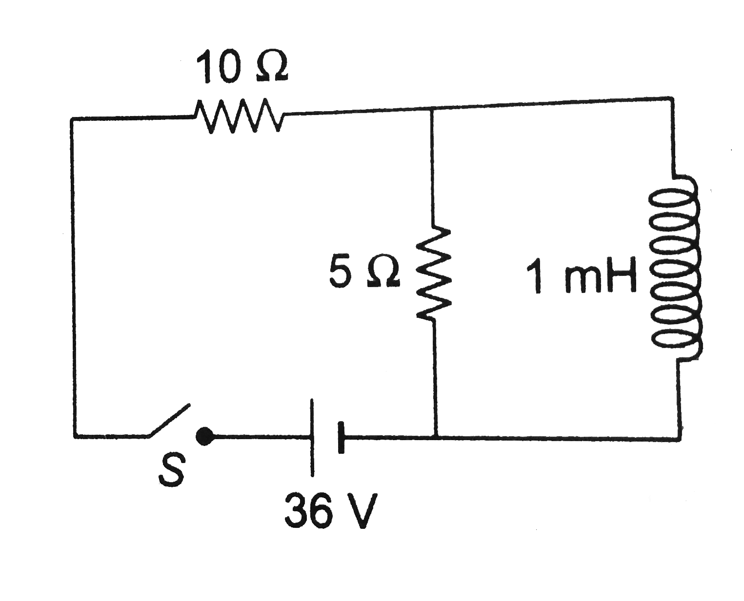
View SolutionIn the circuit arrangement shown in figure, the switch S is closed at t=0. Find the current in the inductance as a function of time? Does the current through 10Ω resistor vary with time or remains constant.
View Solution
Knowledge Check
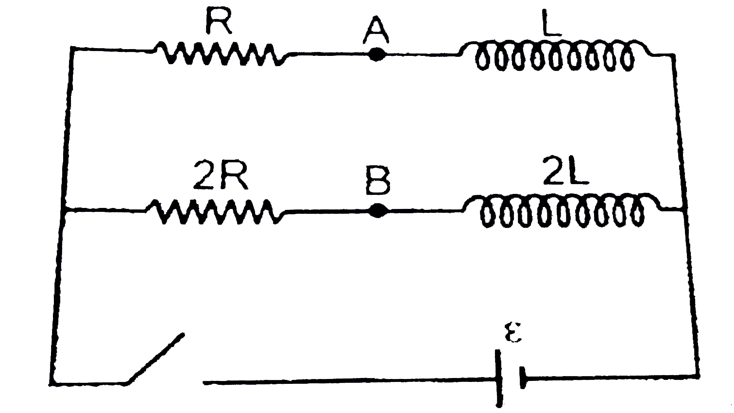
In given LR circuit the switch S is closed at time t=0 thenAThe ratio of induced emfs in the inductors of inductance L and 2L will be constantBThe ratio of induced emfs in the inductor of inductance L and 2L will be time varyingCthe potential difference VA−VB increases with timeDThe potential difference VA−VB will be constantIn the circuit shown in figure switch S is closed at time t=0
Takin left to right current through the indcutor as apositive current, current through inductor varies with time asA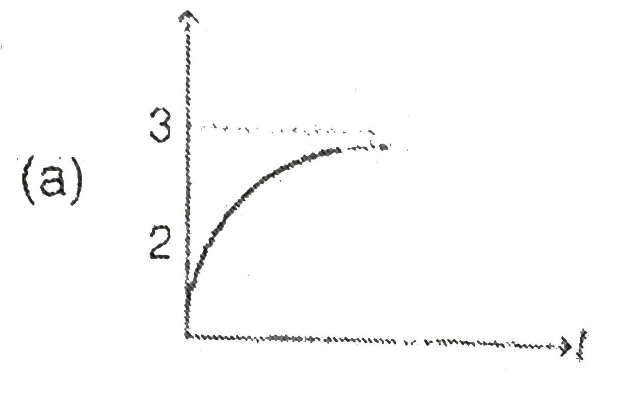 B
B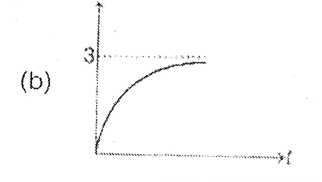 C
C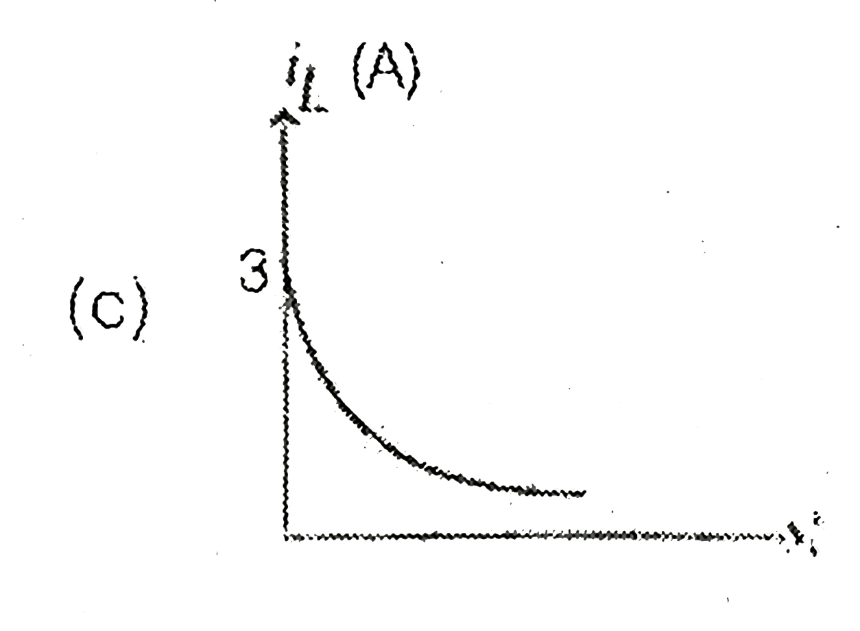 D
D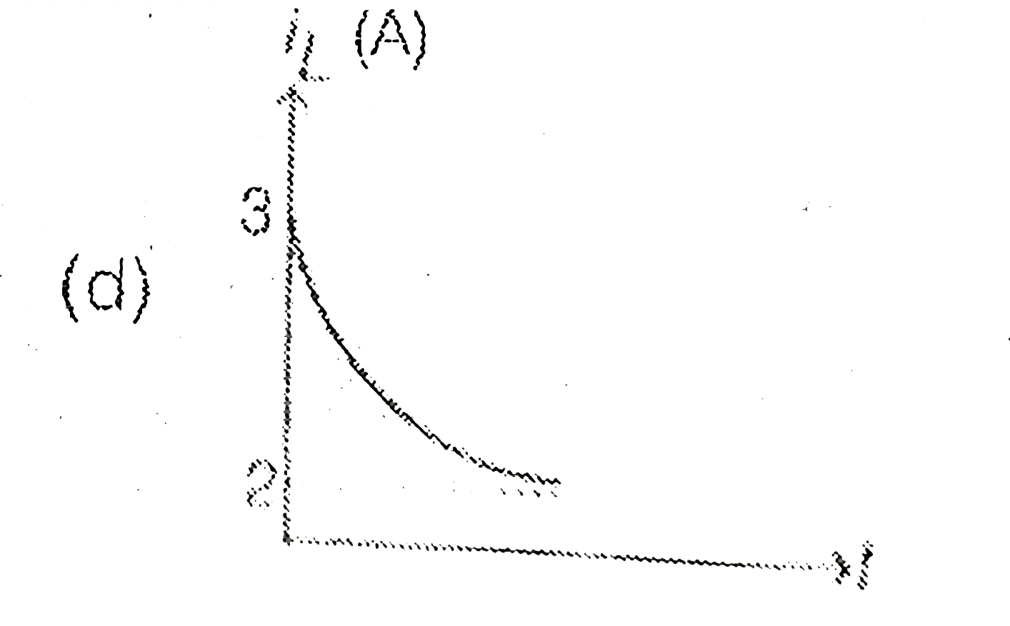
In the circuit shown if Fig. the switch S is closed at time t = 0. The current through the capacitor and inductor will be equal at time t equal (given R=√L/C
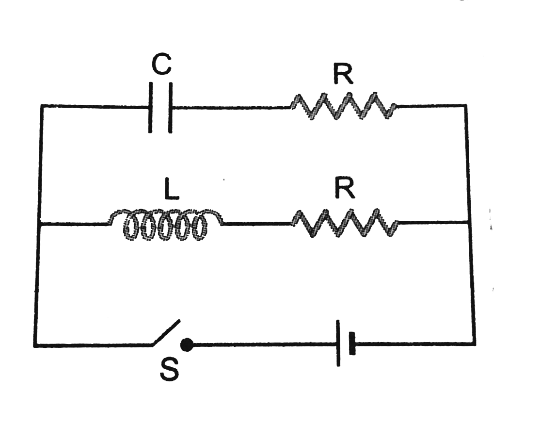 ARCBRCloge2C1RlogeDLR
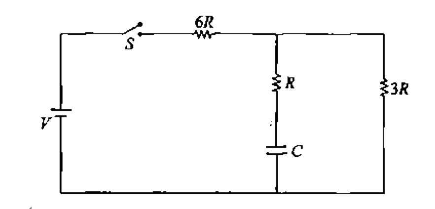
In the circuit shown in figure-3.240 switch S is closed at time t=0. find the current through different wires and charge stored on the capacitor at any time t.
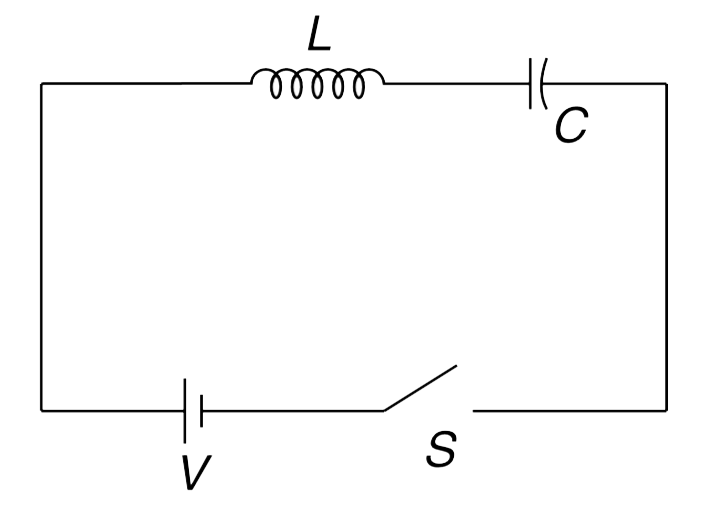
View SolutionIn the circuit shown in the figure, switch S is closed at time t=0.
(a) Write current in the circuit and charge on capacitor as a function of time. Draw the graphical plot for the same.
(b) Find maximum charge on the capacitor. What is potential difference across the inductor when charge on the capacitor is maximum?
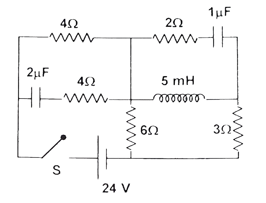
View SolutionIn the circuit shown, the switch 'S' is closed at t=0. Then the current through the battery steady state reached is
View Solutionthere in no current part of this circuit for time t<o. Switch S is closed at t=0.
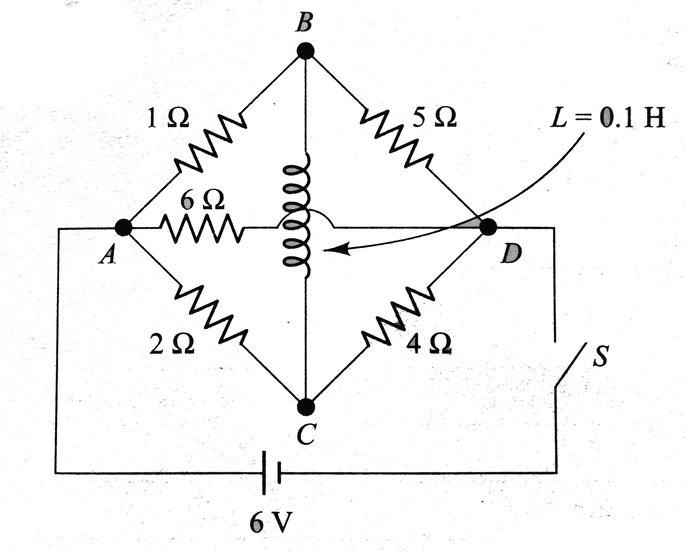
The current through the inductor after a long time will be
View SolutionIn the circuit shown in the figure, switch S is closed at time t=0. Select the correct statements.
View Solution
