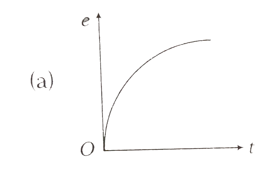
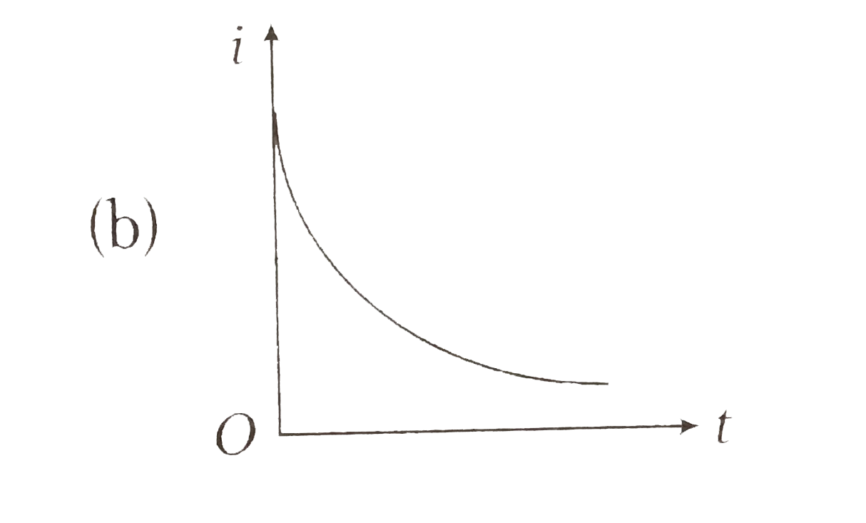
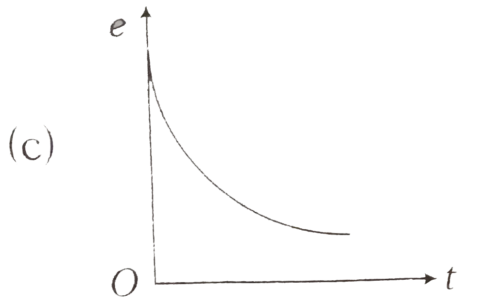
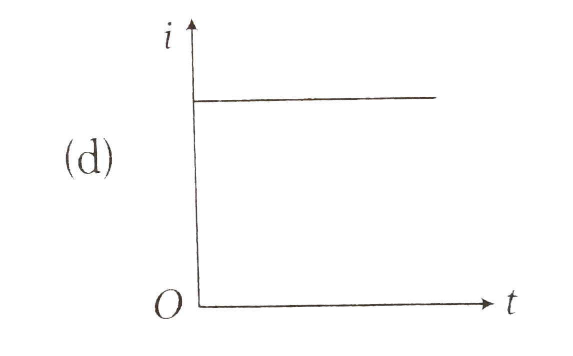
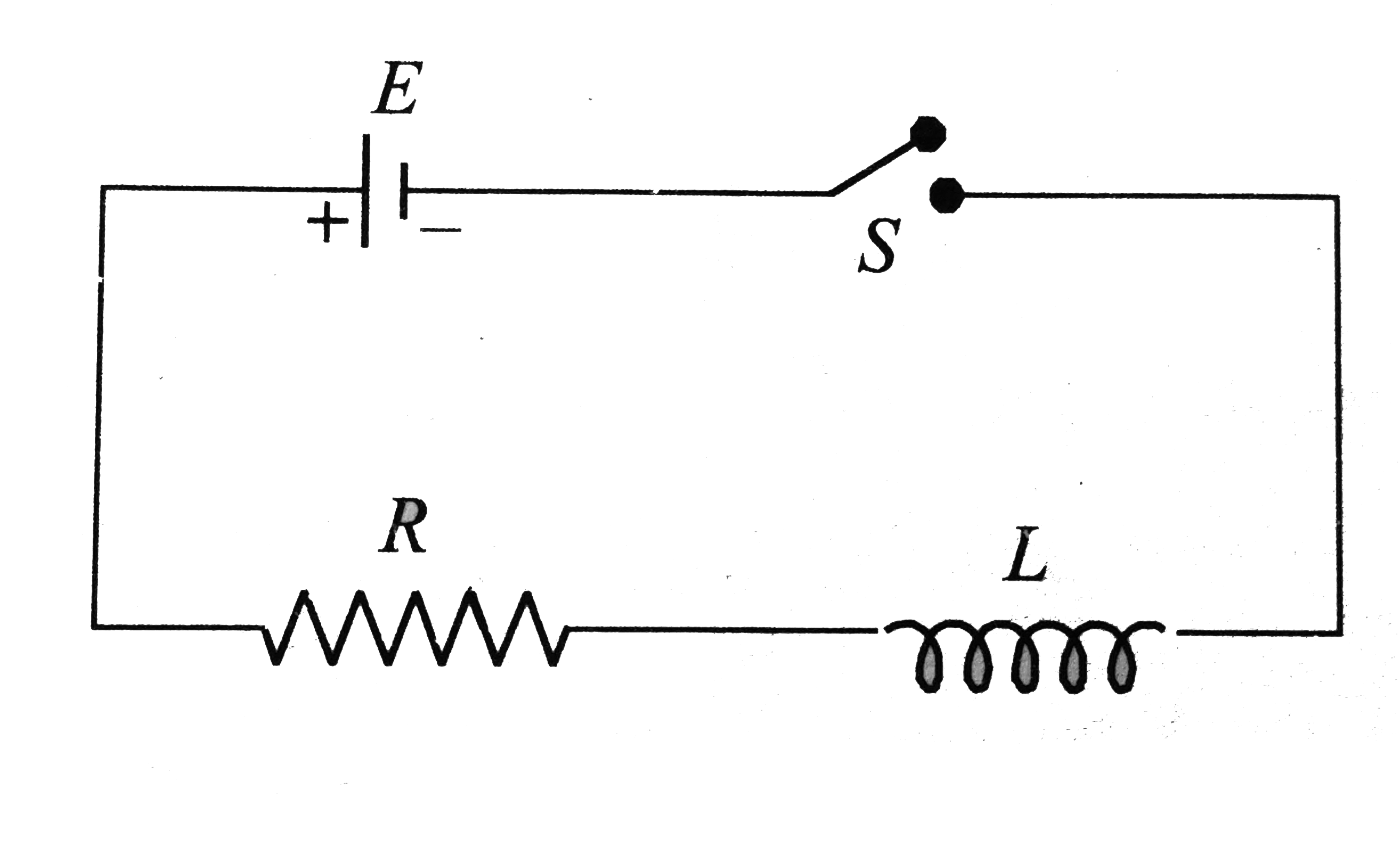
Switch S of the circuit shows in Fig is closed at t=0. If e denotes the induced emf in L and I is the current flowing through the circuit at time t, which of the following graphs is//are correct?

The correct Answer is:C
At t = 0, induced emf e is maximum and is equal to applied emf, but curent i is zero.
After lapse of time, current through the circuit increases but induced emf decreases.
Topper's Solved these Questions
- BOOK - DC PANDEY ENGLISHCHAPTER - ELECTROMAGNETIC INDUCTIONEXERCISE - Medical entrance special format questions17videos
ELECTROMAGNETIC INDUCTION
- BOOK - DC PANDEY ENGLISHCHAPTER - ELECTROMAGNETIC INDUCTIONEXERCISE - Match the columns5videos
ELECTROMAGNETIC INDUCTION
- BOOK - DC PANDEY ENGLISHCHAPTER - ELECTROMAGNETIC INDUCTIONEXERCISE - Check point60videos
ELECTROMAGNETIC INDUCTION
- BOOK - DC PANDEY ENGLISHCHAPTER - CURRENT ELECTRICITYEXERCISE - Medical entrances gallery97videos
CURRENT ELECTRICITY
- BOOK - DC PANDEY ENGLISHCHAPTER - ELECTROMAGNETIC WAVESEXERCISE - Sec C22videos
ELECTROMAGNETIC WAVES
Similar Questions
Switch S of the circuit shows in Fig. is closed at t=0. If e denotes the induced emf in L and i the current flowing through the circuit at time t, then which of the following graphs correctly represents the variation of e with i?
 View Solution
In an L-R circuit connected to a battery of constant emf E, switch is closed at time t=0. If e denotes the induced emf across inductor and I the current in the circuit at any time t. Then which of the following graphs shown the variation of e with i?
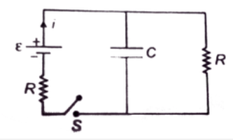
View SolutionIn the circuit shown, the switch is closed at t=0. Select the correct alternative(s)
 View Solution
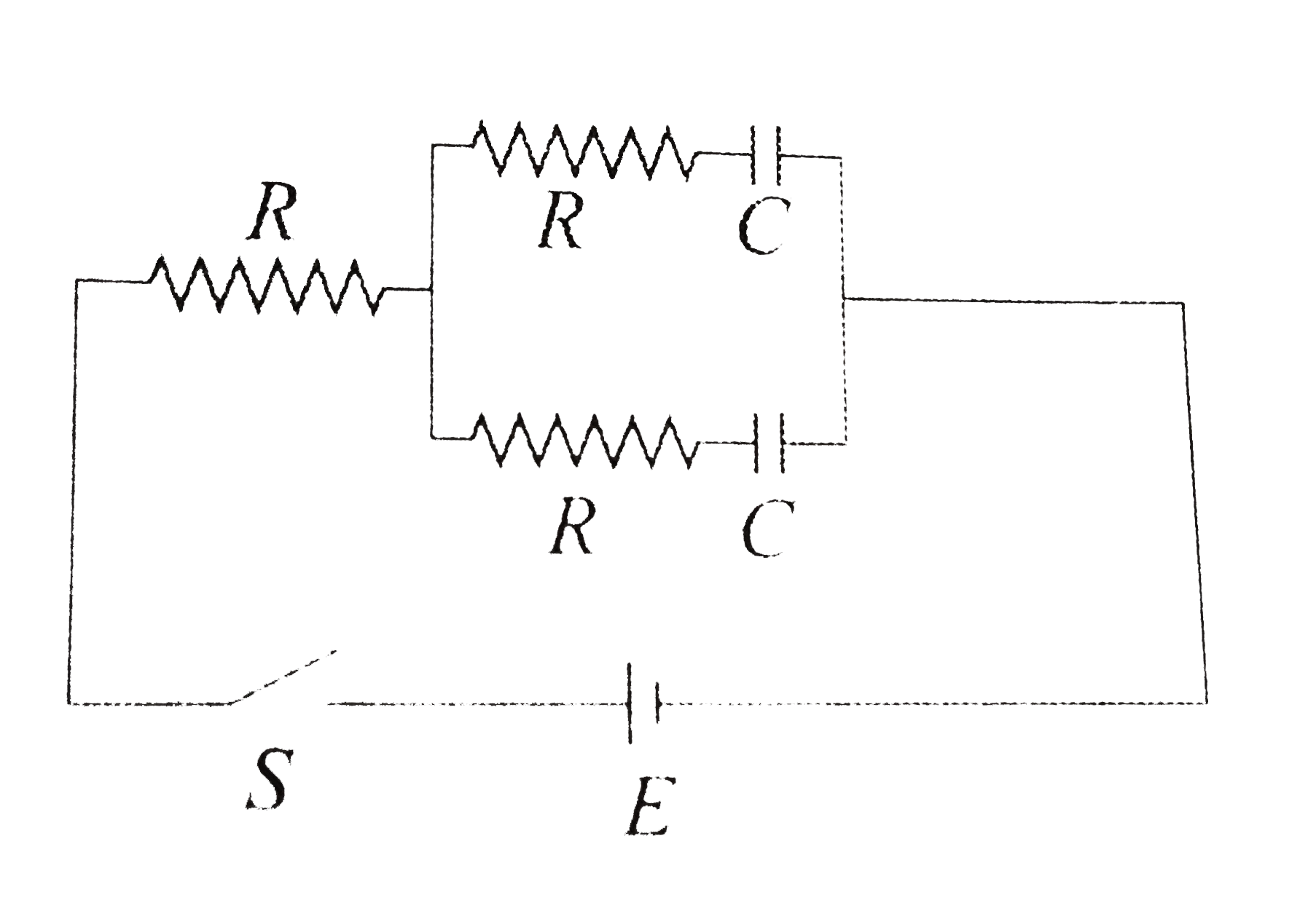
The switch S in the circuit diagram is closed at t = 0. The charge on capacitors at any time is
 View Solution
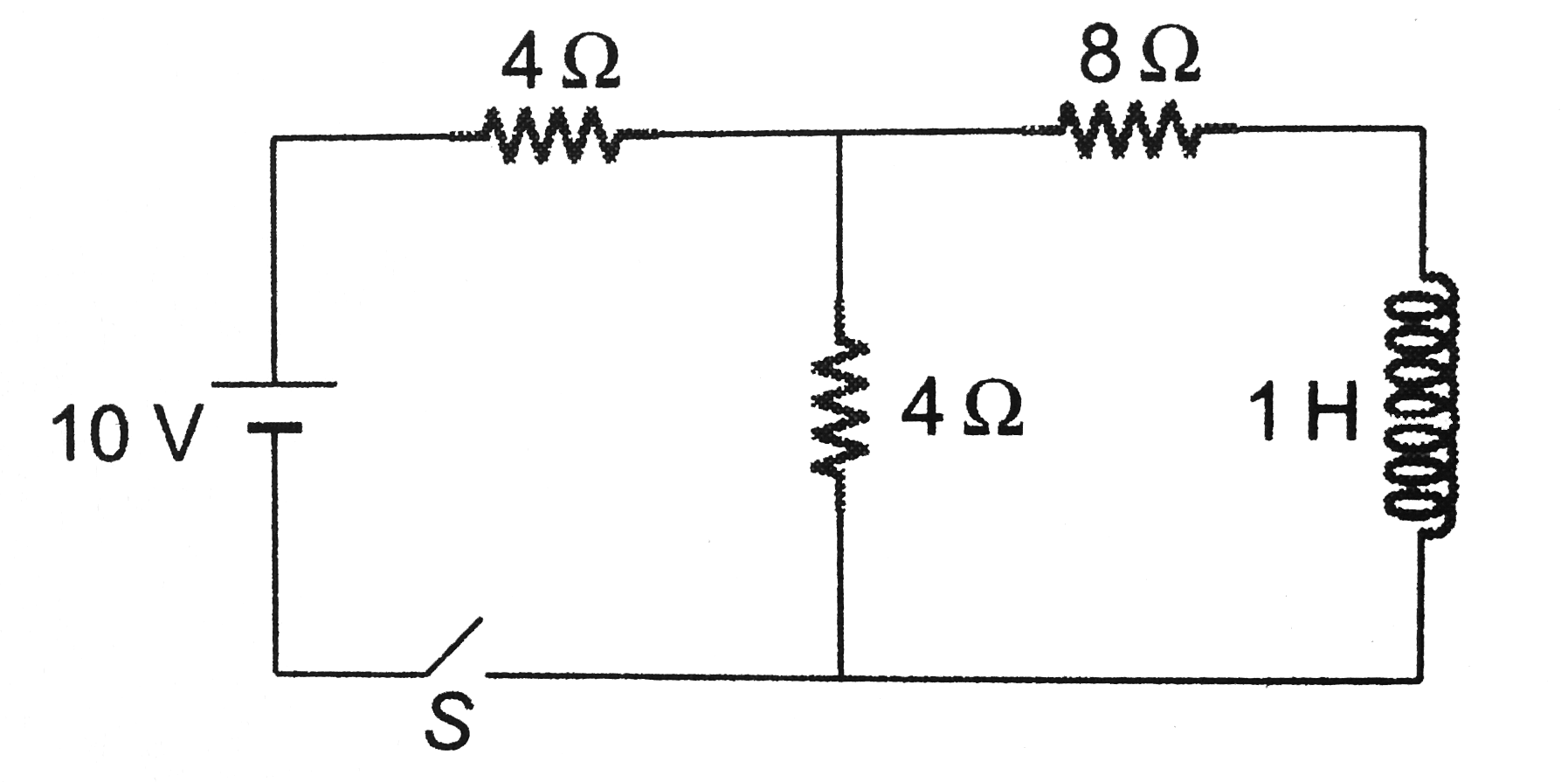
The switch in figure is closed at time t=0. Find the current in the inductor and the current through the switch as functions of time thereafter.
 View Solution
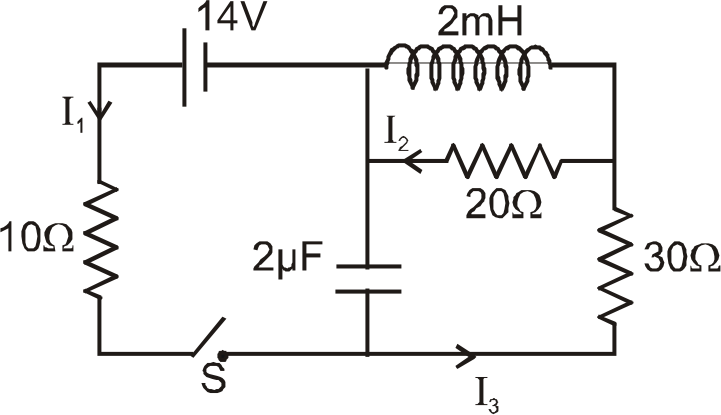
In the circuit shown, the switch is closed at t=0, the currents I1,I2 and I3 are
 View Solution
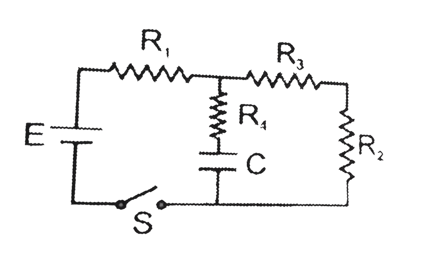
In the circuit shown in figure the switch S is closed at t = 0. A long time after closing the switch
 View Solution
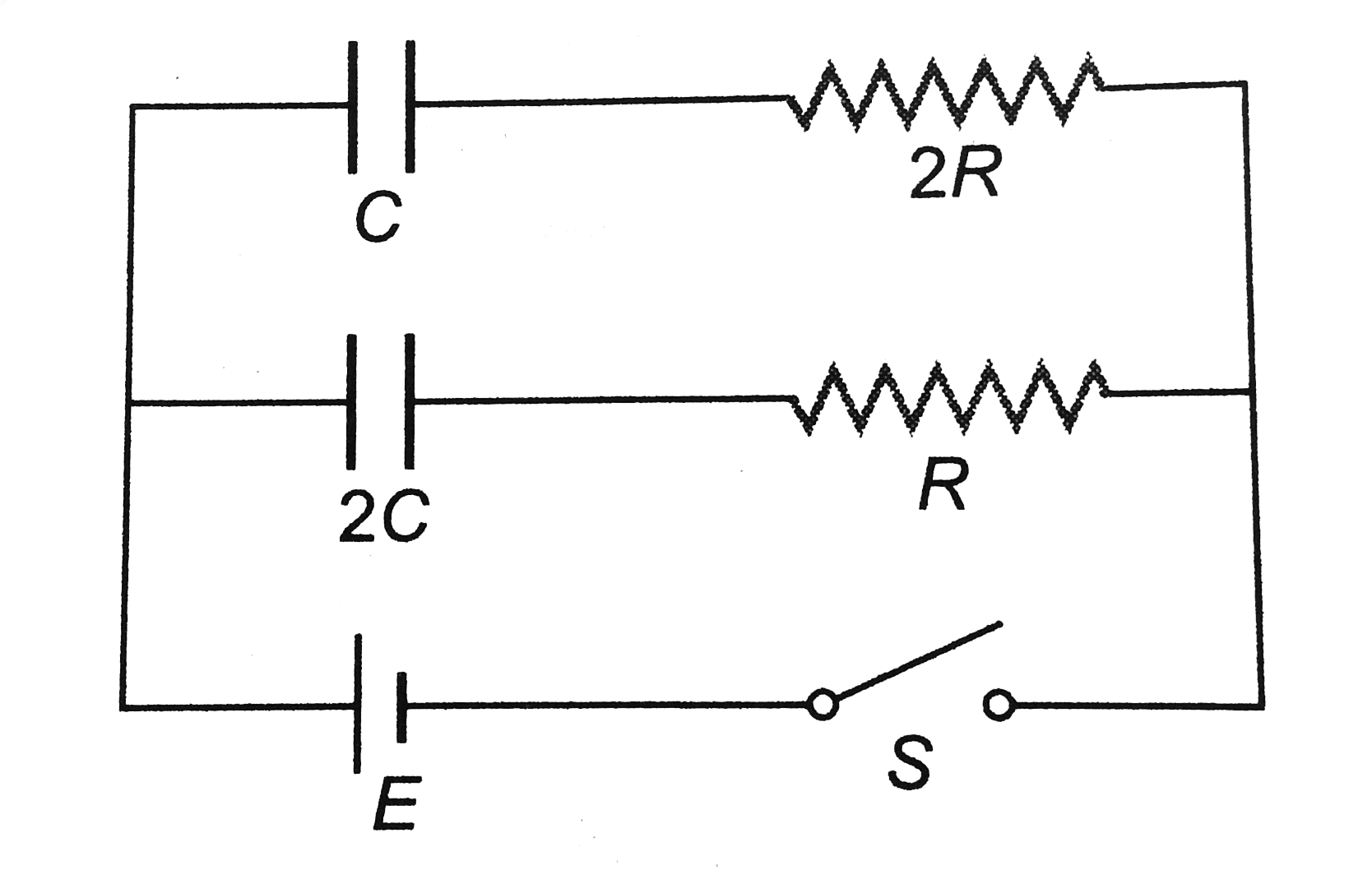
In the circuit shown in the figure, switch S is closed at time t=0. Select the correct statements.
 View Solution
In the circuit shown in the figure, switch S is closed at time t=0. Select the correct statements.
 View Solution
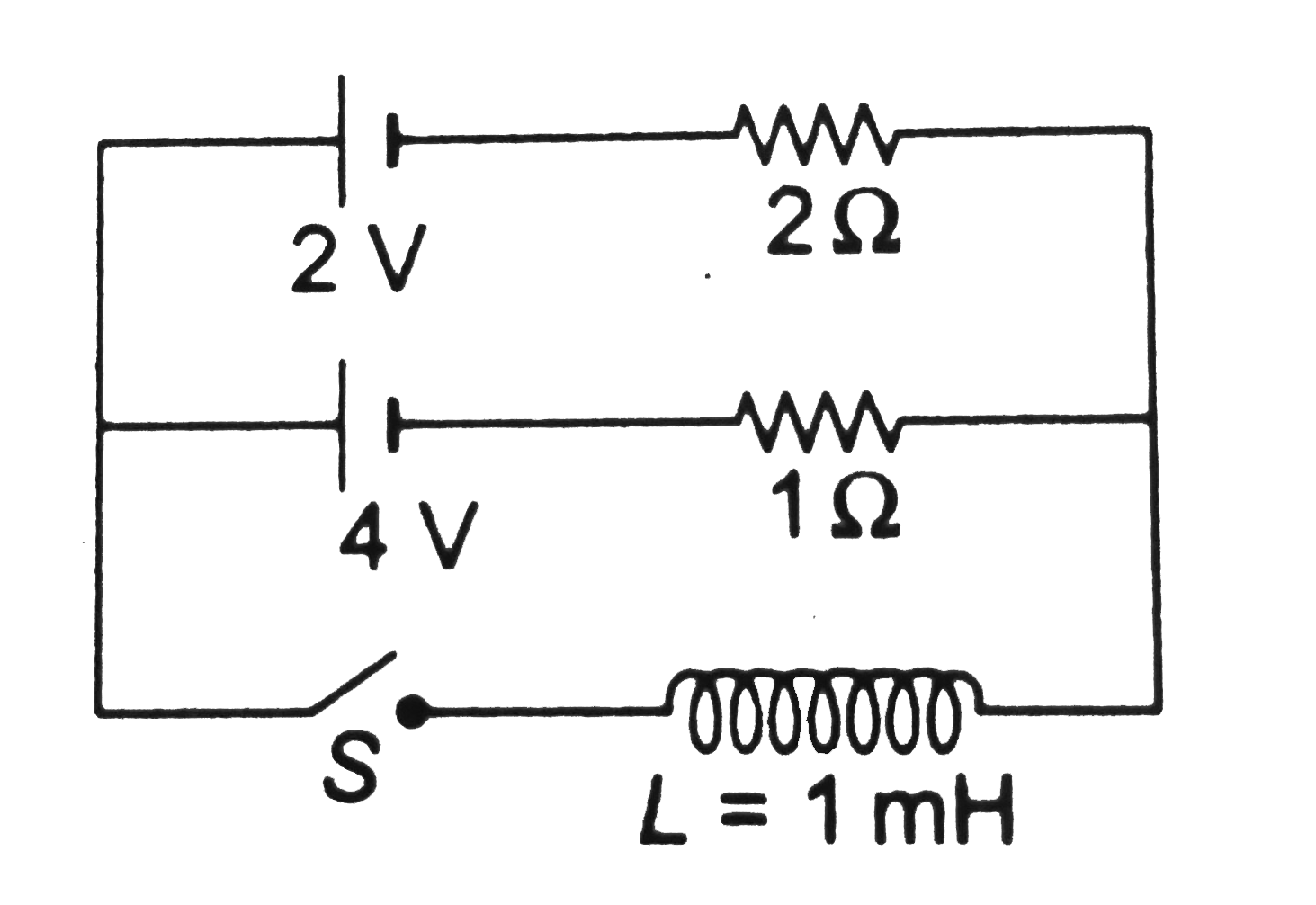
In the circuit shown, switch S is closed at time t=0. Find the current through the inductor as a function of time t.
 View Solution

