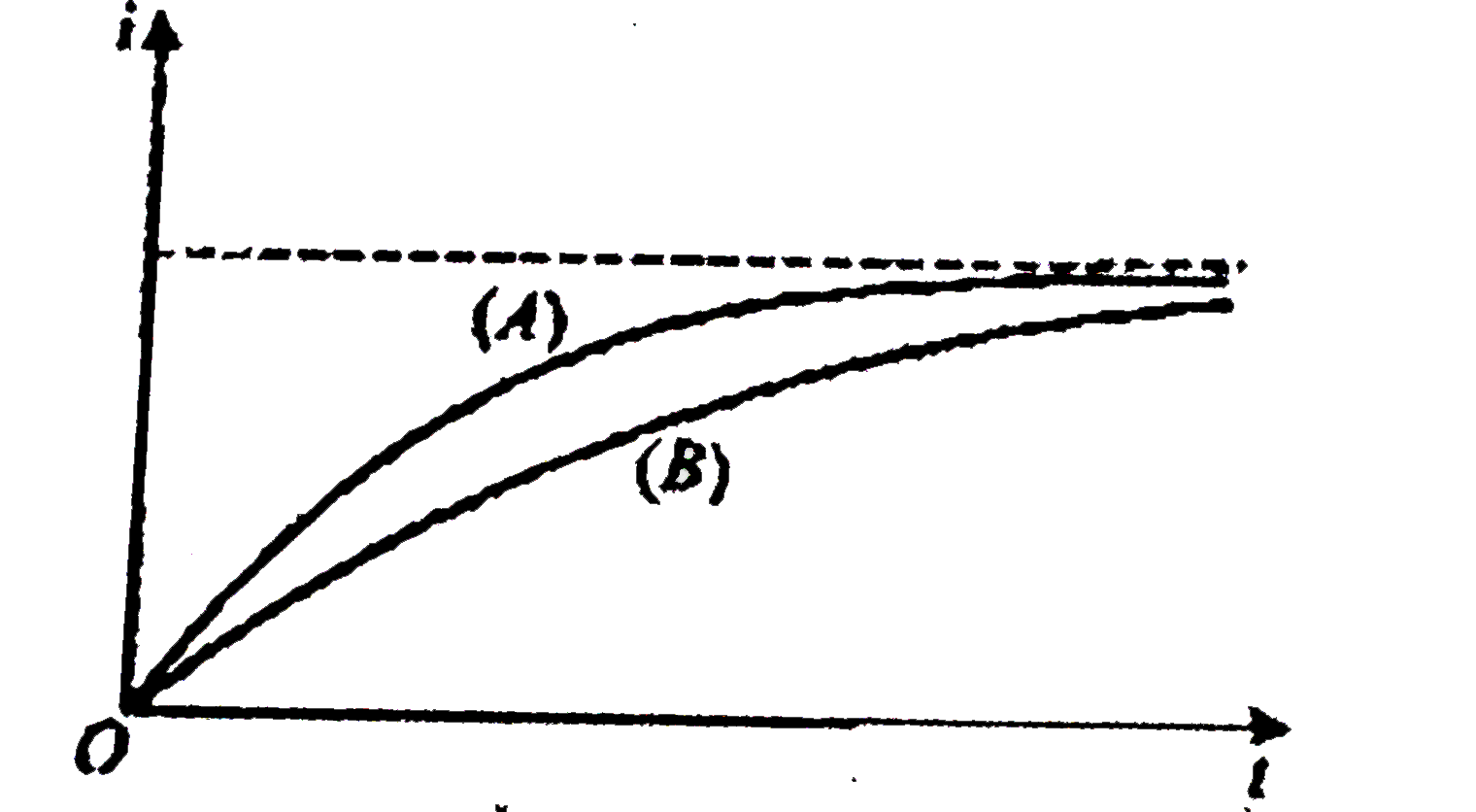
When a battery is connected across a series combination of self inductance L and resistance R , the variation in the current i with time t is best represented by
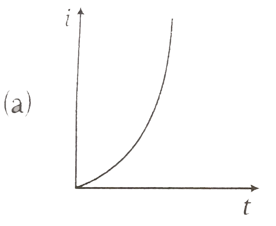
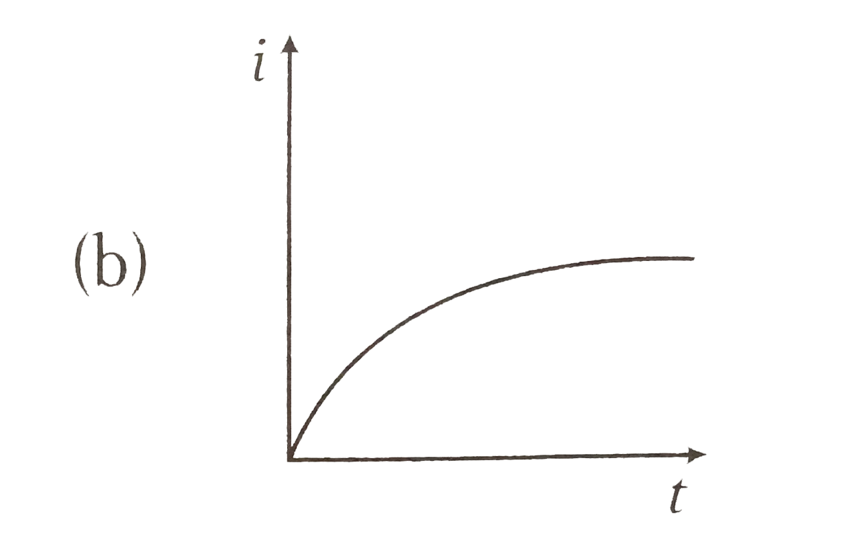
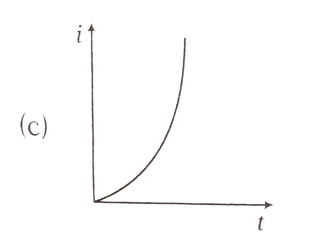
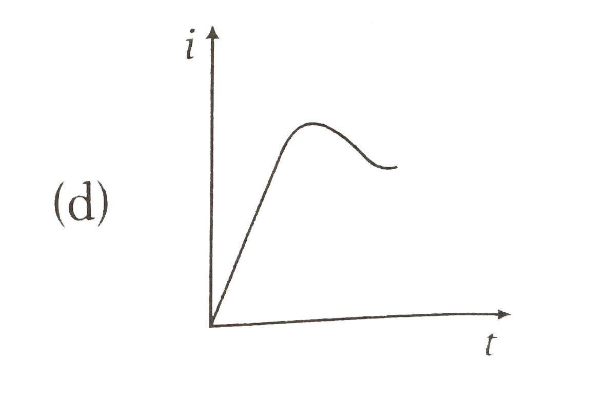
The correct Answer is:B
To solve the problem of how the current i varies with time t when a battery is connected across a series combination of self-inductance L and resistance R, we can follow these steps:
Step 1: Understand the Circuit
When a battery is connected to a series circuit consisting of a resistor R and an inductor L, the current does not instantly reach its maximum value. Instead, it increases gradually over time due to the inductance.
Step 2: Write the Current Equation
The current i(t) in an LR circuit can be described by the equation:
i(t)=Imax(1−e−tτ)
where:
- Imax=ER (the maximum current, where E is the emf of the battery),
- τ=LR (the time constant of the circuit).
Step 3: Analyze the Current at Specific Times
- At t=0:
i(0)=Imax(1−e0)=Imax⋅0=0
This indicates that the current starts at zero when the switch is first closed.
- At t→∞:
i(∞)=Imax(1−e−∞)=Imax⋅1=Imax
This shows that the current approaches its maximum value as time goes on.
Step 4: Graphical Representation
The equation i(t)=Imax(1−e−tτ) describes an exponential rise. The graph starts at zero when t=0 and asymptotically approaches Imax as t increases.
Step 5: Identify the Correct Option
Based on the description of the current's behavior over time, the correct graphical representation is an exponential curve that starts at zero and rises towards Imax. This matches option B.
Conclusion
The variation in the current i with time t when a battery is connected across a series combination of self-inductance L and resistance R is best represented by option B.
---
When a battery is connected to a series circuit consisting of a resistor R and an inductor L, the current does not instantly reach its maximum value. Instead, it increases gradually over time due to the inductance.
The current i(t) in an LR circuit can be described by the equation:
i(t)=Imax(1−e−tτ)
where:
- Imax=ER (the maximum current, where E is the emf of the battery),
- τ=LR (the time constant of the circuit).
- At t=0:
i(0)=Imax(1−e0)=Imax⋅0=0
This indicates that the current starts at zero when the switch is first closed.
i(∞)=Imax(1−e−∞)=Imax⋅1=Imax
This shows that the current approaches its maximum value as time goes on.
The equation i(t)=Imax(1−e−tτ) describes an exponential rise. The graph starts at zero when t=0 and asymptotically approaches Imax as t increases.
Based on the description of the current's behavior over time, the correct graphical representation is an exponential curve that starts at zero and rises towards Imax. This matches option B.
The variation in the current i with time t when a battery is connected across a series combination of self-inductance L and resistance R is best represented by option B.
Topper's Solved these Questions
- BOOK - DC PANDEY ENGLISHCHAPTER - ELECTROMAGNETIC INDUCTIONEXERCISE - Medical entrance special format questions17videos
ELECTROMAGNETIC INDUCTION
- BOOK - DC PANDEY ENGLISHCHAPTER - ELECTROMAGNETIC INDUCTIONEXERCISE - Match the columns5videos
ELECTROMAGNETIC INDUCTION
- BOOK - DC PANDEY ENGLISHCHAPTER - ELECTROMAGNETIC INDUCTIONEXERCISE - Check point60videos
ELECTROMAGNETIC INDUCTION
- BOOK - DC PANDEY ENGLISHCHAPTER - CURRENT ELECTRICITYEXERCISE - Medical entrances gallery97videos
CURRENT ELECTRICITY
- BOOK - DC PANDEY ENGLISHCHAPTER - ELECTROMAGNETIC WAVESEXERCISE - Sec C22videos
ELECTROMAGNETIC WAVES
Similar Questions
A sinusoidal voltage Vsin(at) is applied across a series combination of resistance R and inductor L. The amplitude of the current in the circuit is
View SolutionA cell of e.m.f E and internal resitance r ,is connected to an external resistance R. the variation of potential difference V across the resistance R as function of R as shown in the figure, is the best represented by curve
_PHY_E01_011_Q01.png) View Solution
View SolutionA circuit consisting of a constant EMF E, a self-inductance L and a resistance R in sereis is closed at time t=0. The relation between the current i in the circuit and the time t is as shown by the curve. A in the figure-5.321. when one or more of parameters E,R and L are changed, the curve B is obtained. Then it is possible that:
 View Solution
When a battery connected across a resistor of 16Ω, the voltage across the resistor is 12 V. When the same battery is connected across a resistor of 10Ω, voltage across it is 11 V. The internal resistance of the battery (in ohm) is
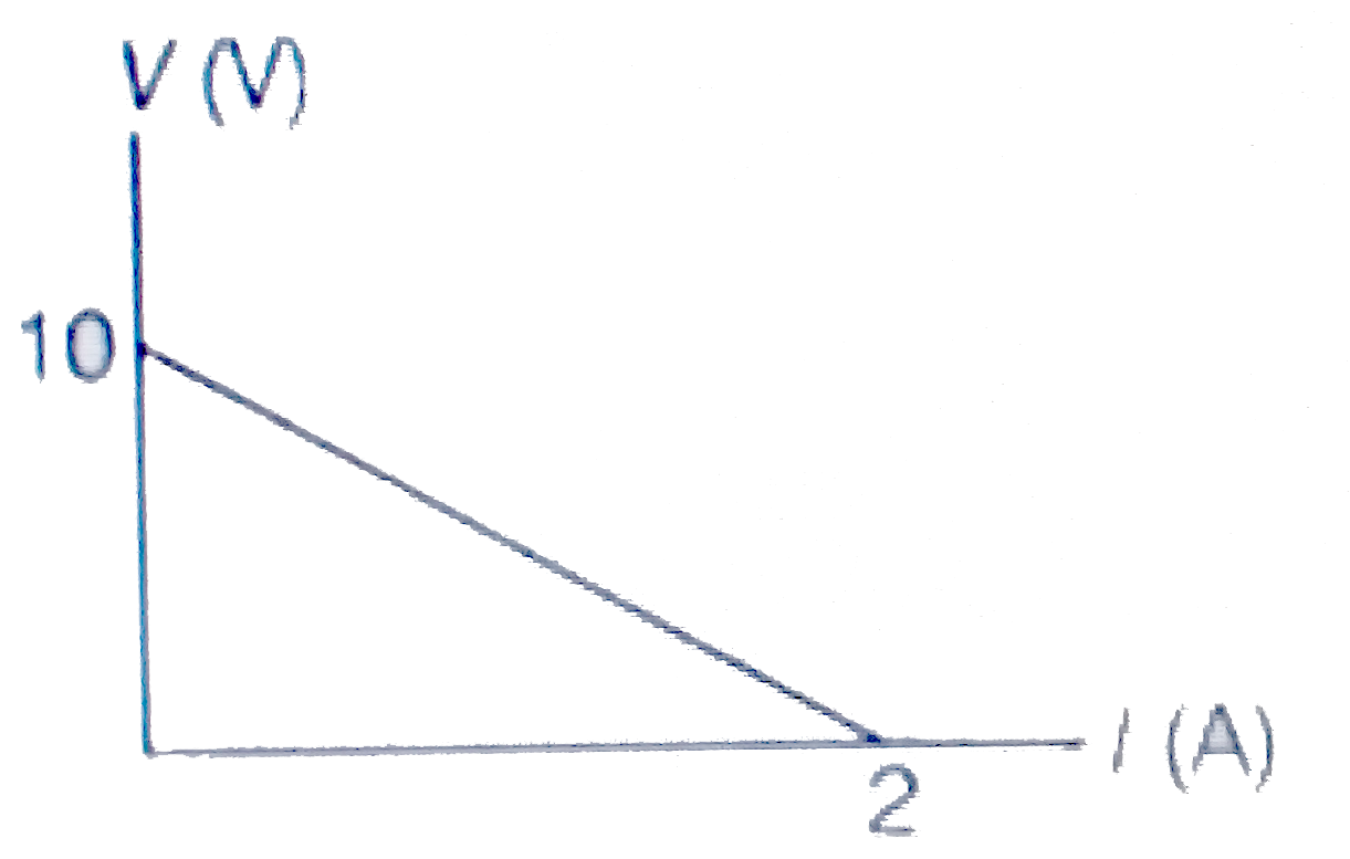
View SolutionA battery of emf E and internal resistance r is connected across a resistance R. Resistance R can be adjusted to any value greater than or equal to zero. A graph is plotted between the current passing through the resistance (I) and potential difference across the termainals of the battery (V). Maximum power developed across the resistance R is
 View Solution
Four equal resistance dissipated 5 W of power together when connected in series to a battery of negligible internal resistance . The total power dissipated in these resistance when connected in parallel across the same battery would be .
View Solutioncells each of emf e and internal resistance r are joined in series to form a row and such rows are connected in parallel to form a battery of N = mn cells. If this battery is connected to an external resistance R.
Show that current f flowing through the external resistance R is given by :
I=NemR+nrView SolutionA battery of emf epsilon and internal resistance r is connected across a load resistance RL . The plot between output power and load resistance is shown in the figure. The value of emf epsilon and internal resistance r respectively will
_PHY_E05_112_Q01.png) View Solution
View SolutionAn inductor 20×10−3 a capacitor 100(μ)F and a resistor 50Ω are connected in series across a source of emf V=10sin314t.
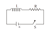
If resistance is removed from the circuit and the value of inductance is doubled, the variation of current with time in the new circuit isView SolutionAs shown in the figure, a battery of emf is connected to an inductor L and resistance R in series. The switch is closed at . The total charge that flows from the battery, between t=te and t=2te (te is the time constant of the circuit) is:
 View Solution

