Complete Solutions to Level 5 of chapter CURRENT ELECTRICITY of Class 12 book with complete answers and questions
| Class 12 | PHYSICS |
| Chapter | CURRENT ELECTRICITY |
| NARAYANA | Level 5 |
| Number Of Questions | 42 |
| Academic Year | 2023-24 |
A piece of copper and another of germanium are cooled from room temperature to `80 K`. The resistance of
View SolutionRead the following statements carefully :
Y : The resistivity of a semiconductor decreases with increase of temperature.
Z : In a conducing solid, the rate of collisions between free electrons and ions increase with increase of temperature.
Select the correct statement (s) from the followin :
View SolutionA Steady current flows in a metalic conductor of non uniform cross section. The quantity/quantities which remain constant along the length of the conductor is/are
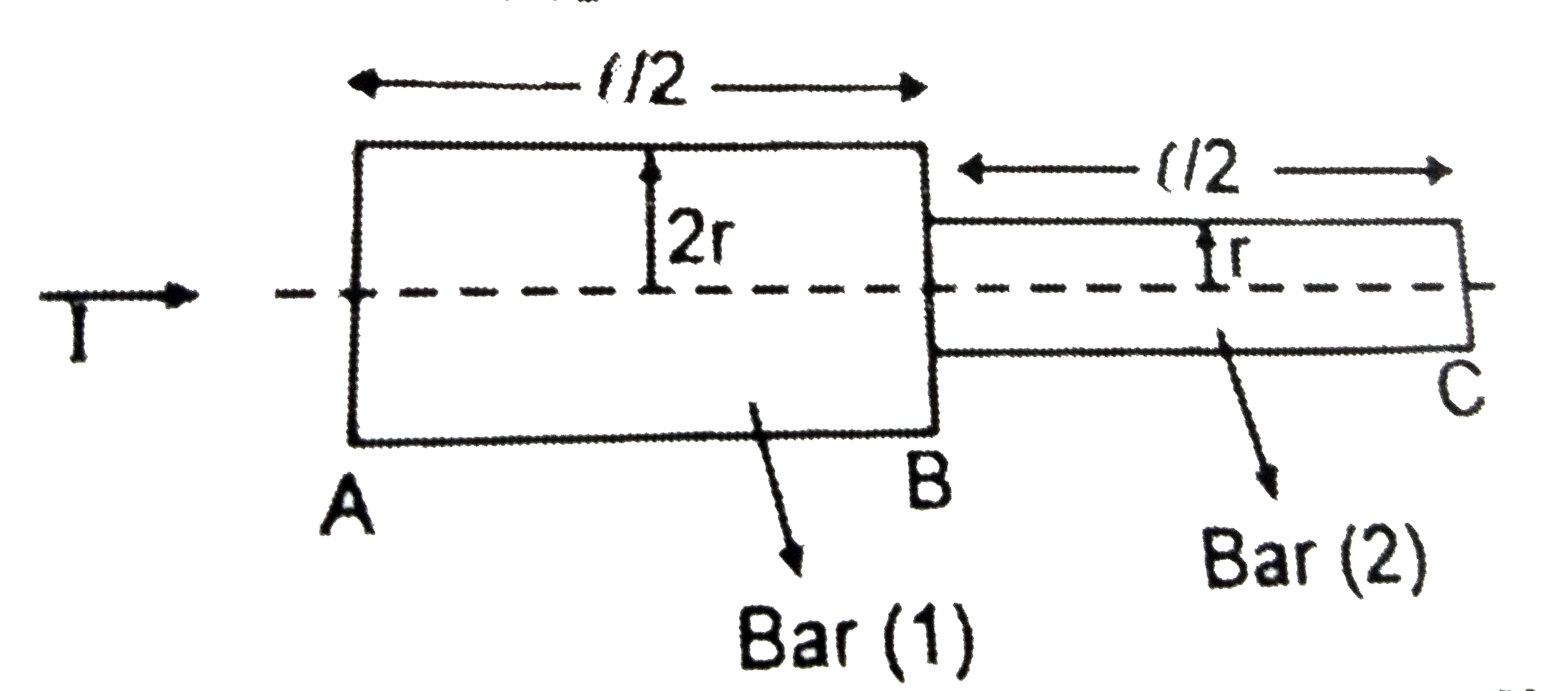
View SolutionTwo bars of equal resistivity `rho` and radius 'r' and '2r' are kept in contact as show. An electric current is passed through the bars. Which one of the following is correct ?
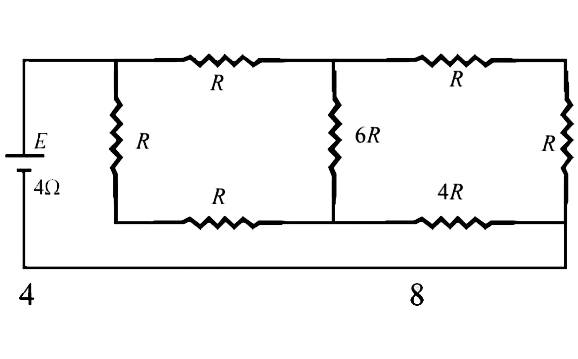
View SolutionA battery of internal resistance `4Omega` is connected to the network of resistance as shown . In order that the maximum power can be delivered to the network, the value of R in `Omega` should be
 .
.
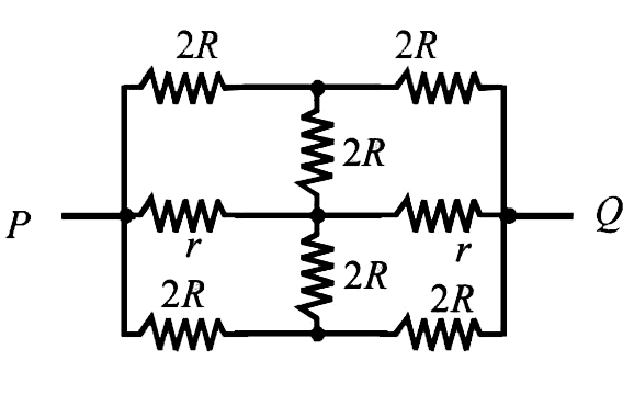
View SolutionThe effective resistance between points P and Q of the
electrical circuit shown in the figure is
(a) `(2Rr)/(R+r)`
(b)`(8R(R+r))/(3R +r)`
(c) `2r + 4R`
(d) `(5R)/2 + 2r` .
 .
.
View Solution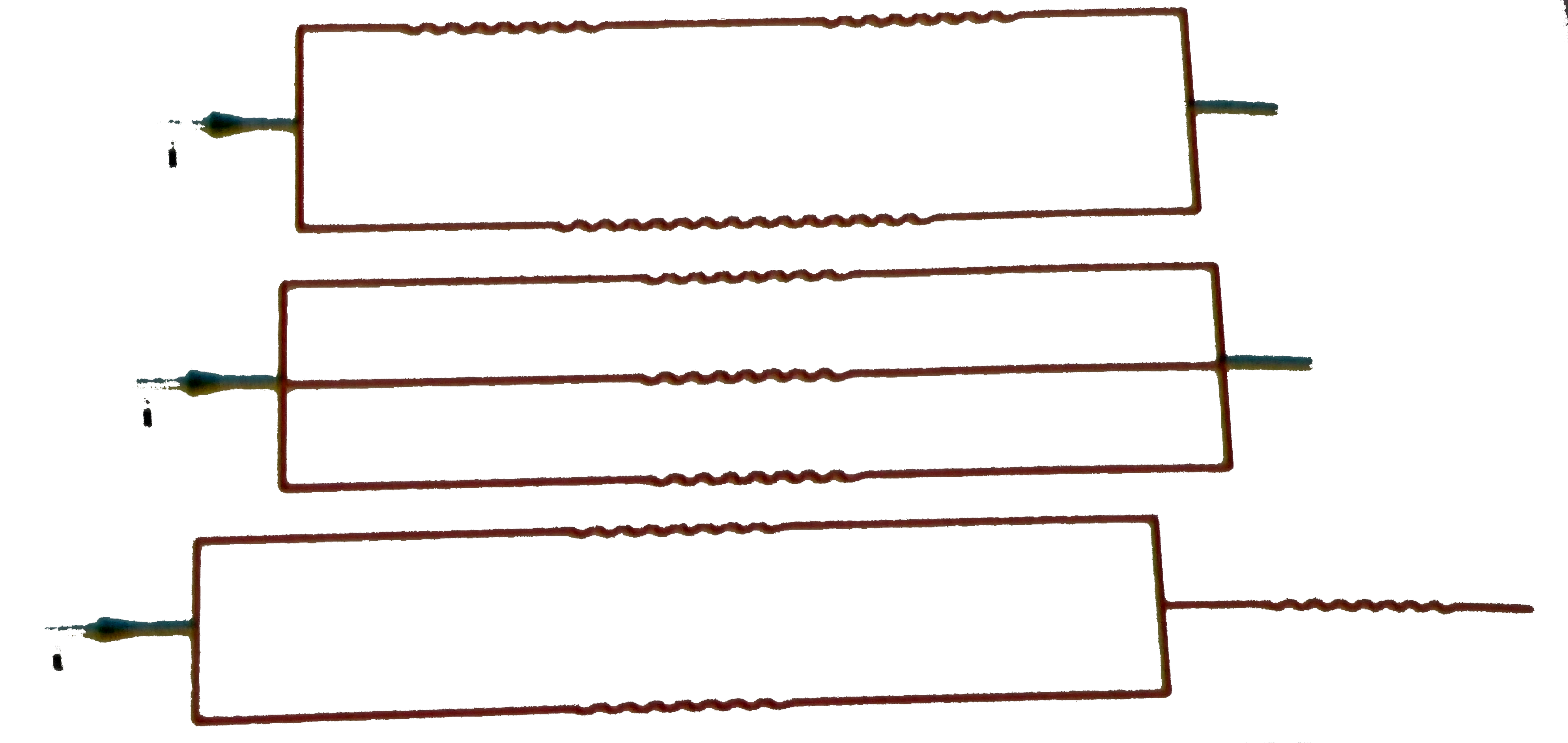
The three resistances of equal value are arranged in the different combinations shown below. Arrange them in increasing order of power dissipation
View Solution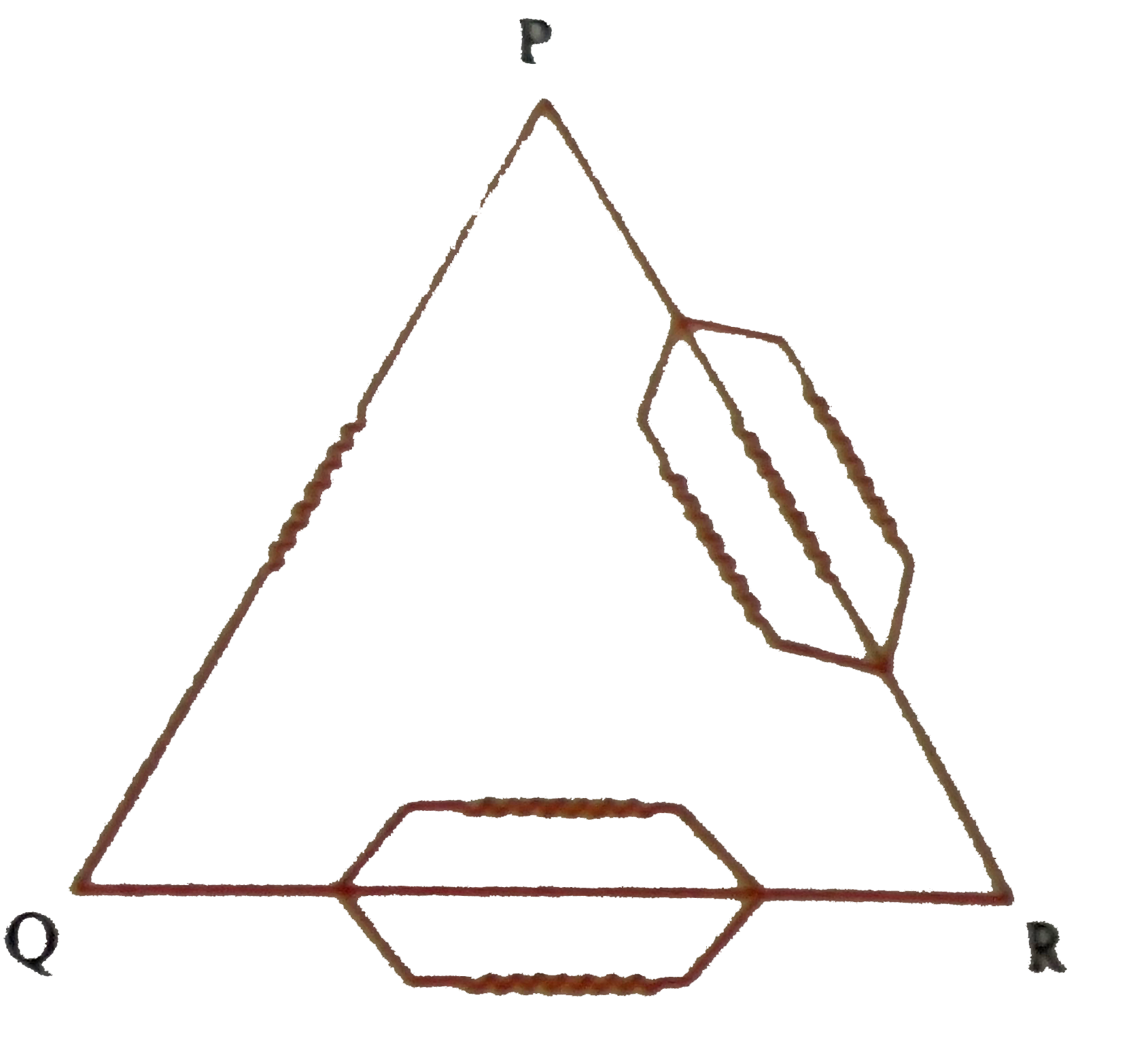
Six equal resistances are connected between points P, Q and R as shown in the figure. Then the net resistance will be maximum between
View SolutionA rigid container with thermally insulated walls contains a coil of resistance `100Omega`, carrying current 1A. Change in internal energy after 5 min will be
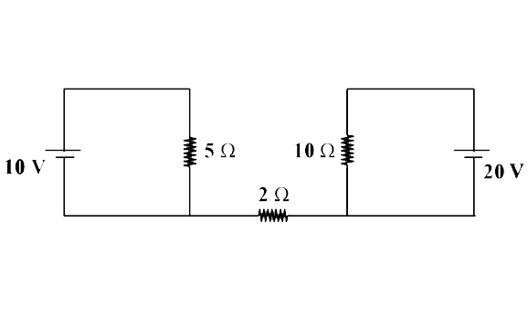
View SolutionFind out the value of current through `2Omega` resistance for the given circuit.
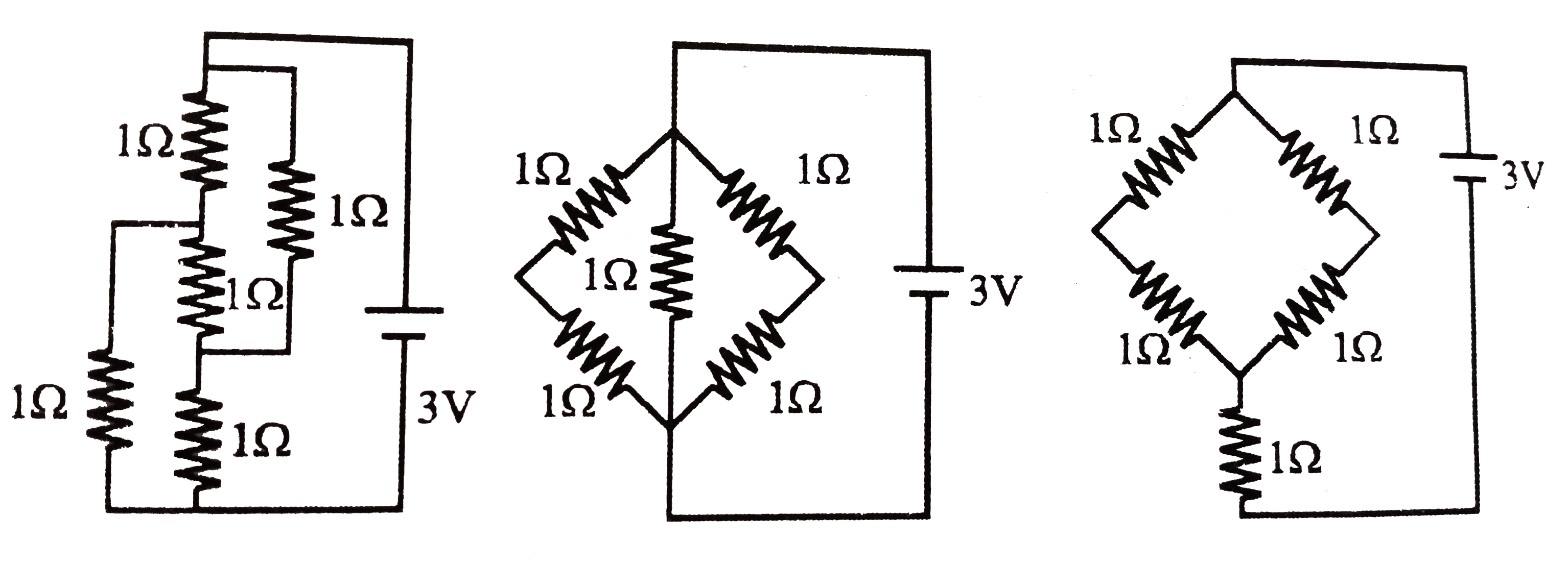
View SolutionFigure shows three resistor configurations `R_(1),R_(2)` and `R_(3)` connected to `3V` battery. If the power dissipated by the configurations `R_(1),R_(2)` and `R_(3)` is `P_(1),P_(2)` and `P_(3)` respectively, then
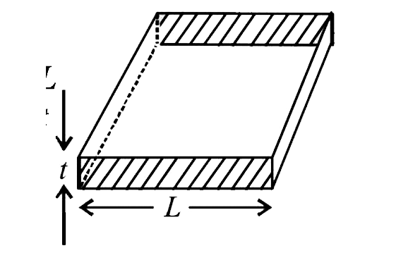
View SolutionConsider a thin square sheet of side L and thickness t, made of a material of resistivity `rho`. The resistance between two opposite faces, shown by the shaded areas in the figure is
View SolutionIncandescent bulbs are designed by keeping in mind that the resistance of their filament increases with the increase in temperature. If at room temperature, `100W, 60W and 40W` bulbs have filament resistances `R_(100), R_(60) and R_(40)`, respectively, the relation between these resistances is
View SolutionIn the circuit shown in fig the heat produced in the 5 ohm resistor due to the current flowing through it is 10 calories per second.
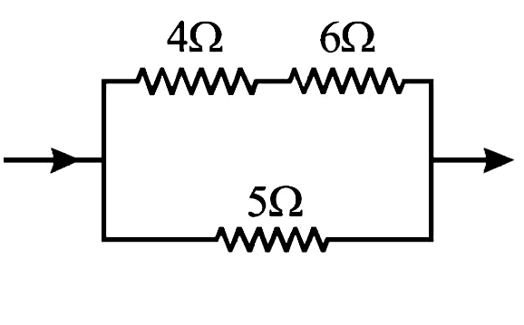
The heat generated in the 4 ohms resistor is
View Solution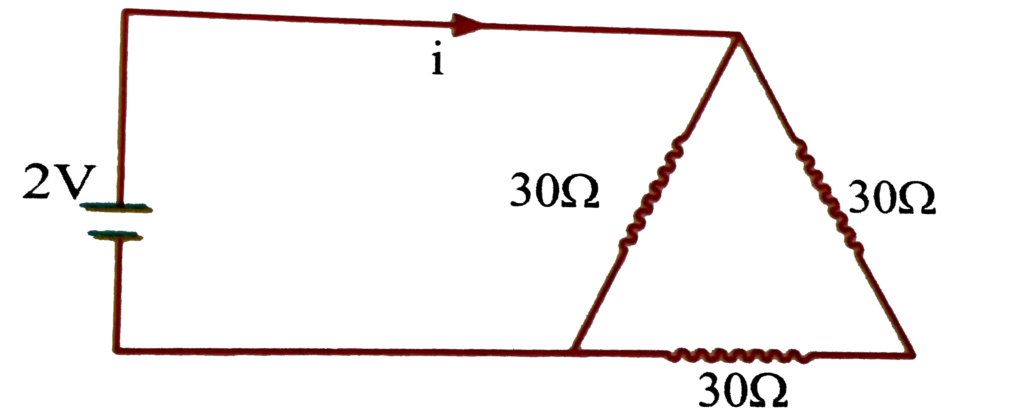
The current `i` in the circuit (see figure) is
View Solution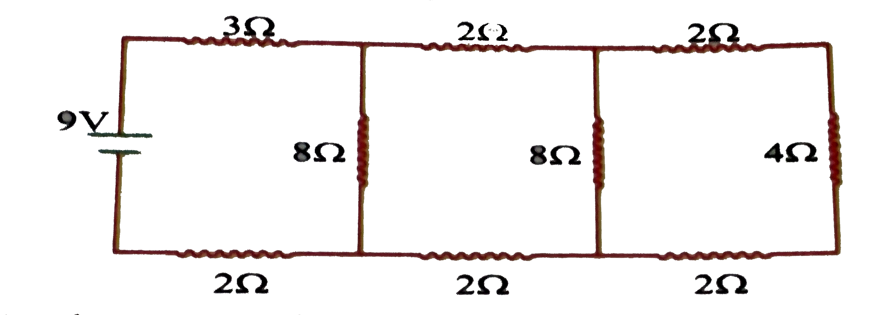
In the circuit shown in the figure, the current through
View SolutionIn the given circuit, it is observed that the current I is independent of the value of the resistance `R_6`. Then the resistance values must satisfy
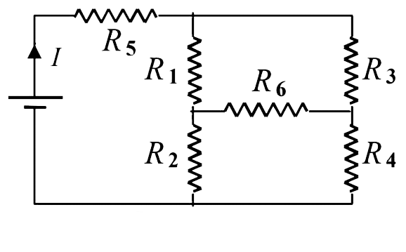 .
.
View SolutionA wire of length L and 3 identical cells of negligible internal resistance are connected in series. Due to the current, the temperature of the wire is raised by `DeltaT` in a time t. A number N of similar cells is now connected in series with a wire of the same material and cross-section but of length 2L. The temperature of the wire is raised by the same amount `DeltaT` in the same time t. the value of N is
View Solution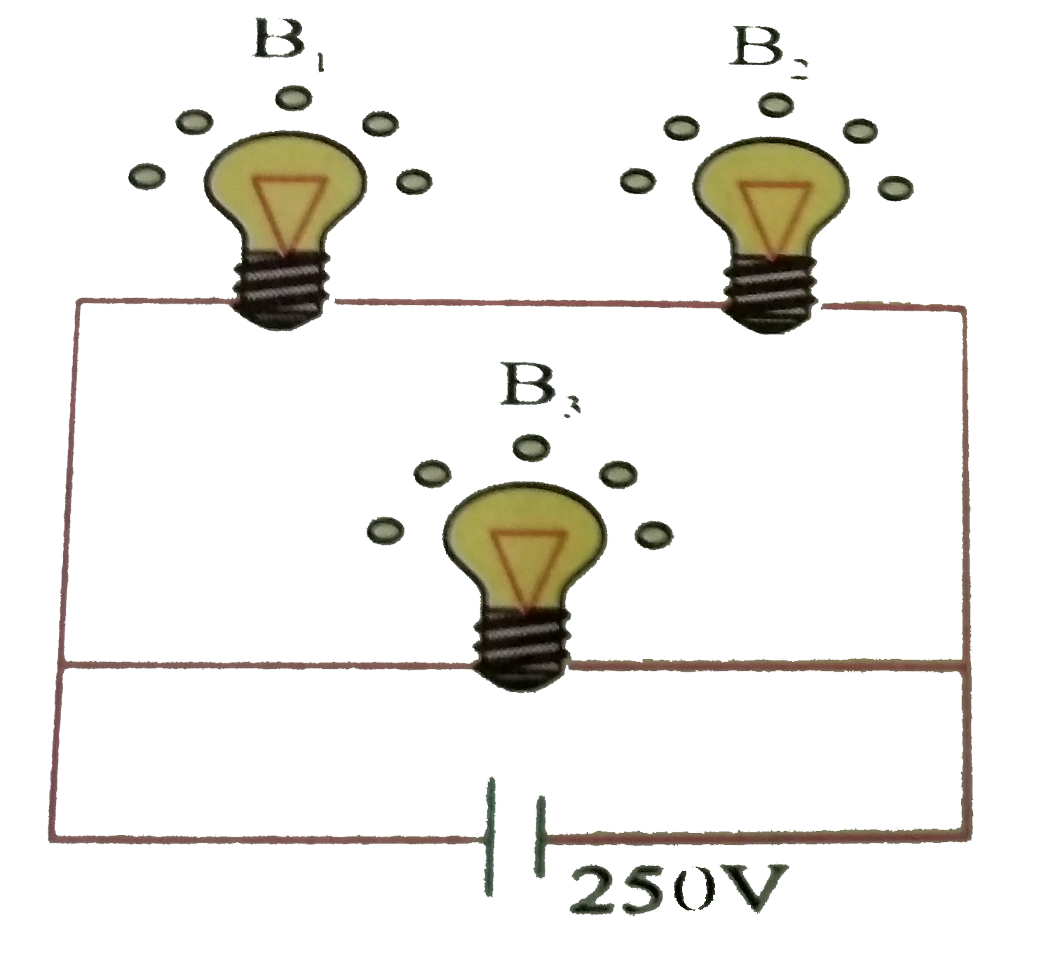
A 100 W bulb `B_(1)` and two 60 W bulbs `B_(2)` and `B_(3)`, are connected to a 250V source, as shown in the figure now `W_(1),W_(2)` and `W_(3)` are the output powers of the bulbs `B_(1),B_(2)` and `B_(3)` respectively then
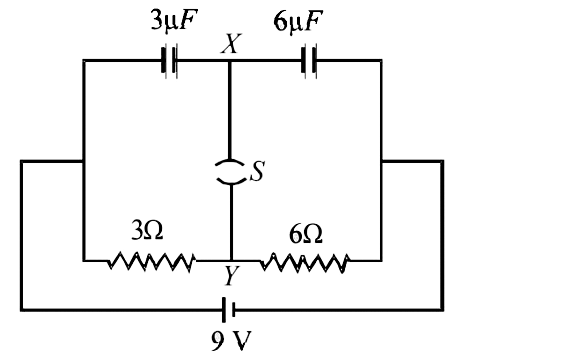
View SolutionA circuit is connected as shown in the figure with the switch S open. When the switch is closed, the total amount of charge that flows from Y to X is
 .
.
View SolutionA resistance of `2Omega` is connected across one gap of a meter bridge (the length of the wire is `100 cm`) and an unknown resistance, greater than `2Omega`is conneted across the other gap. When these resistances are interchanged, the balance point shifts by `20 cm`. Neglecting any corrections,the unknown resistance is
View Solution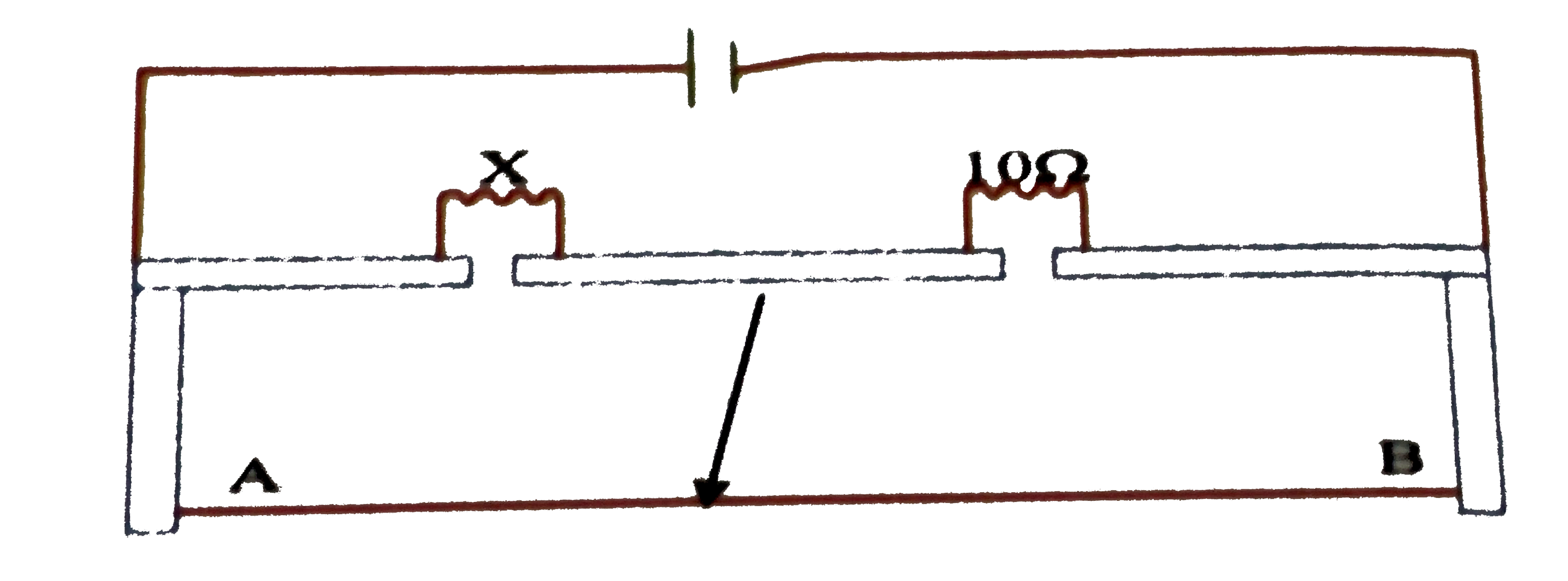
A meter bridge is set-up as shown in figure to determine an unknown resistance X using a standard `10Omega` resistor. The galvanometer shown null point when tapping key is at 52 cm mark. The end corrections are 1 cm and 2 cm respectively for the ends A and B. the determined value of X is
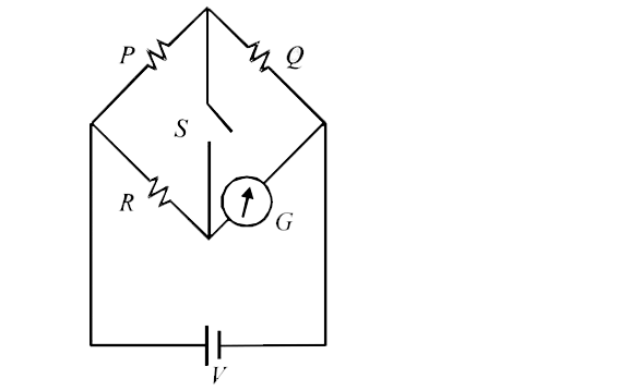
View SolutionIn the circuit `P != R, ` the reading of the galvanometer is same with switch S open or closed. Then
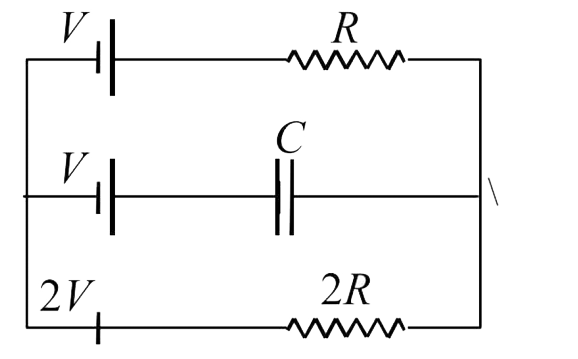
View SolutionIn the given circuit, with steady current, the potential drop across the capacitor must be
View SolutionExpress which of the following set ups can be used to verify
ohm's law?
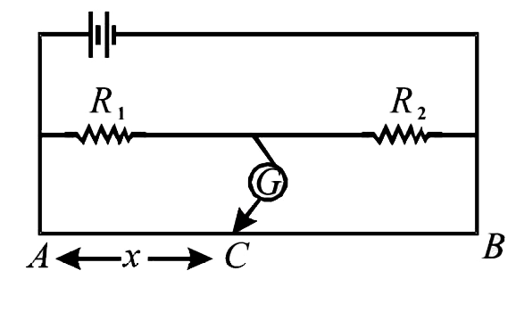
View SolutionIn the shown arrangement of the experiment of the meter bridge if AC corroesponding to null deflection of galvanometer is x, what would be its value if the radius of the wire AB is doubled?
 .
.
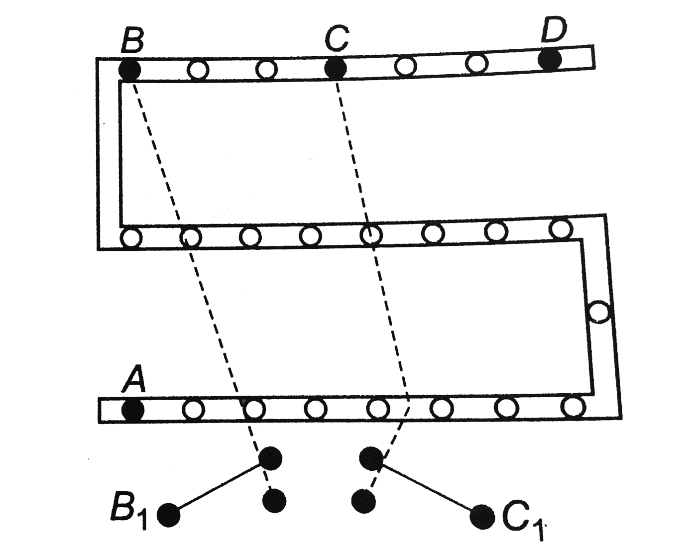
View SolutionFor the post office arrangement to determine the value of unknown resistance, the unknown resistance should be connected between.
View SolutionA moving coil galvanometer of resistance `100Omega` is used as an ammeter using a resistance `0.1 Omega`. The maximum diflection current in the galvanometer is `100 muA`. Find the minimum current in the circuit so that the ammeter shows maximum deflection
View SolutionTo verify Ohm's law, a student is provided with a test resistor `R_(T)`, a high resistance `R_(1)` . a small resistance `R_(2)`, two identical galvometers `G_(1)` and `G_(2)` and voltage source `V`. The correct circuit to carry out the experiment is.
View SolutionA microameter has a resistance of `100 omega` and a full scale range of ` 50 muA`. It can be used as a voltmeter or as a higher range ammeter provides a resistance is added to it . Pick the correct range and resistance combination(s)
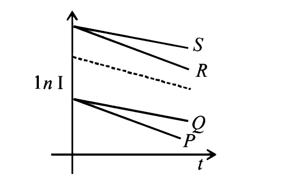
View SolutionA capacitor is charged using an external battery with a resistance x in series. The dashed line showns the variation of In I with respect to time. If the resistance is changed to 2x, the new graph will be
View SolutionA `4 muF` capacitor, a resistance of `2.5 M Omega` is in series with `12V` battery. Find the time after which the potential difference across the capacitor is 3 times the potential difference across the resistor. [ Given In (2) = 0.693]
View Solution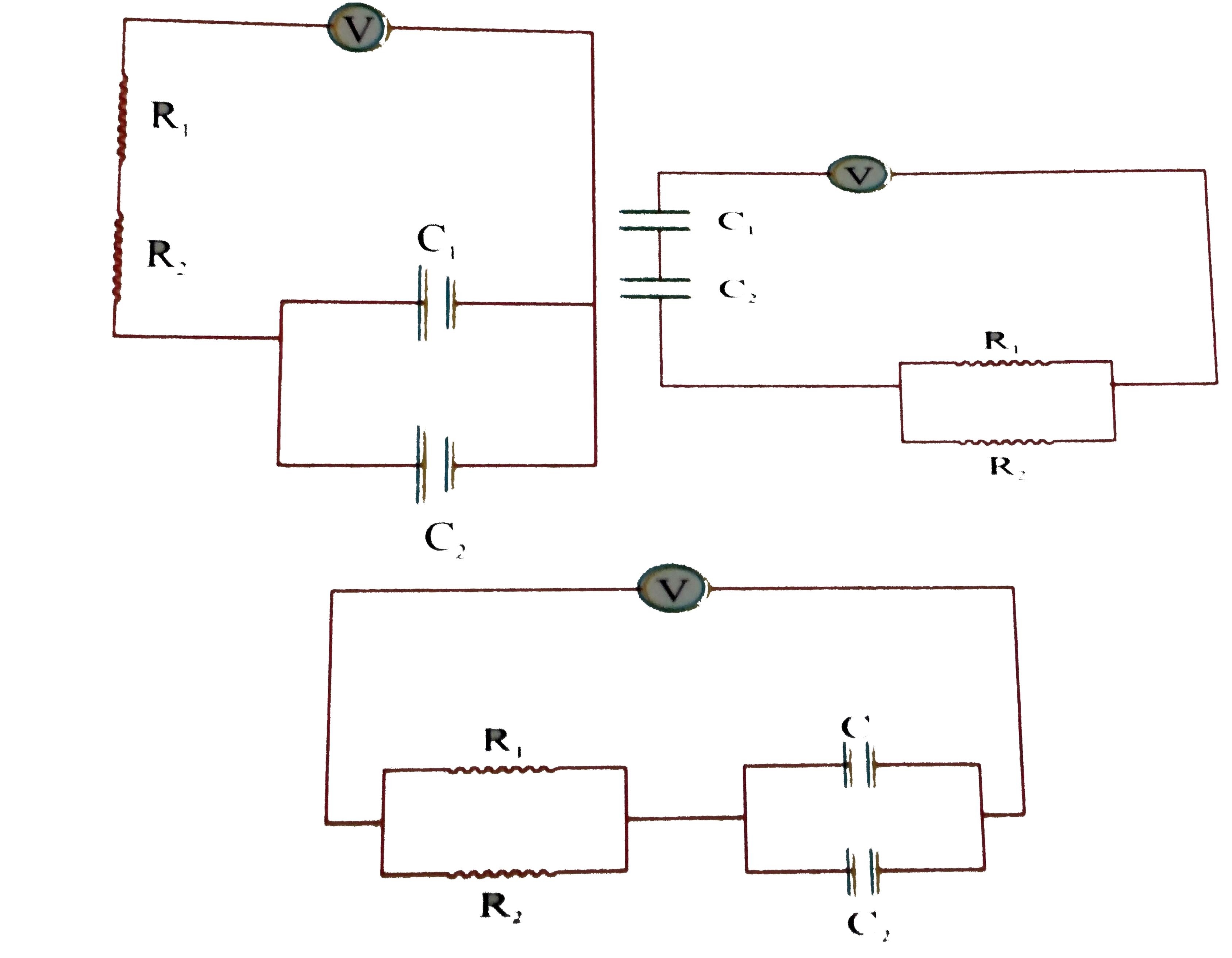
Find the time constant for the given RC circuits in correct order (in `mus`)
`R_(1)=1Omega,R_(2)=2Omega,C_(1)=4muF,C_(2)=2muF`
View SolutionCapacitor `C_1` of capacitance 1 micro-farad and capacitor `C_2` of capacitance 2 microfarad are separately charged fully by a common battery. The two capacitors are then separately allowed to discharged through equal resistors at time t = 0.
View SolutionAn infinite line charge of uniform electric charge density `lambda` lies along the axis of an electrically conducting infinite cylindrical shell of radius R. At time `t=0`, the space inside the cylinder is filled with a material of permittivity `epsilon` and electrical conductivity `sigma`. The electrical conduction in the material follows Ohm's law. Which one of the following graphs best describes the subsequent variation of the magnitude of current density j(t) at any point in the material ?
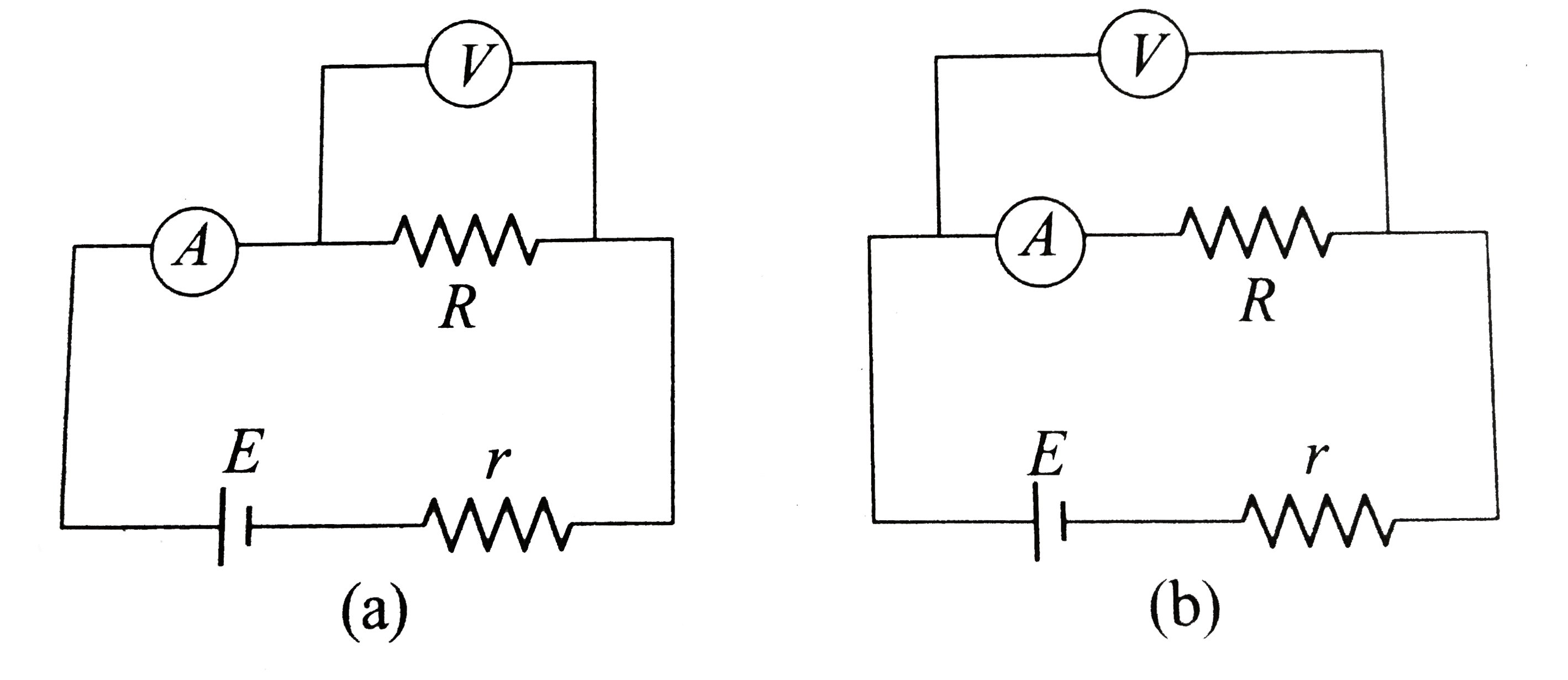
View SolutionThe value of resistance of an unknown resistor is calculated using the formula `R = V//I ` where V and I are the readings of the voltmeter and the ammeter, respectivley. Consider the circuits below. The internal resistances of the voltmeter and the ammeter `(R_V and R_G, respectively)` are finite and nonzero.
 ,
,
Let `R_(A) and R_(B)` be the calculated values in the two cases A and B , respectively.
The relation between `R_A` and the actual value of R is
View SolutionThe value of resistance of an unknown resistor is calculated using the formula `R = V//I ` where V and I are the readings of the voltmeter and the ammeter, respectivley. Consider the circuits below. The internal resistances of the voltmeter and the ammeter `(R_V and R_G, respectively)` are finite and nonzero.
 ,
,
Let `R_(A) and R_(B)` be the calculated values in the two cases A and B , respectively.
The relation between `R_A` and the actual value of R is
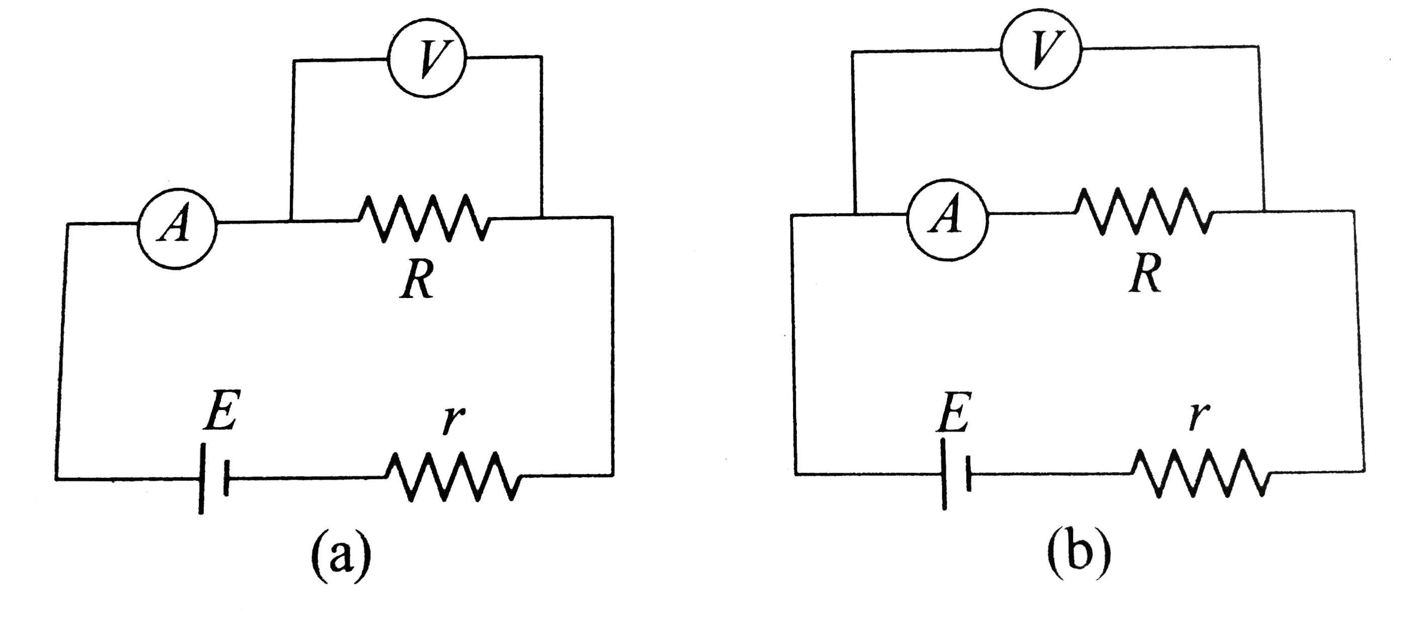
View SolutionThe value of resistance of an unknown resistor is calculated using the formula `R = V//I ` where V and I are the readings of the voltmeter and the ammeter, respectivley. Consider the circuits below. The internal resistances of the voltmeter and the ammeter `(R_V and R_G, respectively)` are finite and nonzero.
 ,
,
Let `R_(A) and R_(B)` be the calculated values in the two cases A and B , respectively.
If the resistance of voltmeter is `R_(V) = 1k Omega` and the percentage error in the measurement of R (the value of R is nearly `10 Omega`)is
View SolutionIn the circuit given in the figure, both batteries are ideal . Emf `E_1` of battery 1 has a fixed value, but emf `E_2` of battery 2 can be varied between `1.0V and 10.0 V` . The graph gives the currents through the two batteries as a function of `E_2` but are not marked as which plot corresponds to which battery. But for both plots, current is assumed to be negative when the direction of the current through the battery is opposite to the direction of that battery's emf (direction of emf is from negative to positive.)
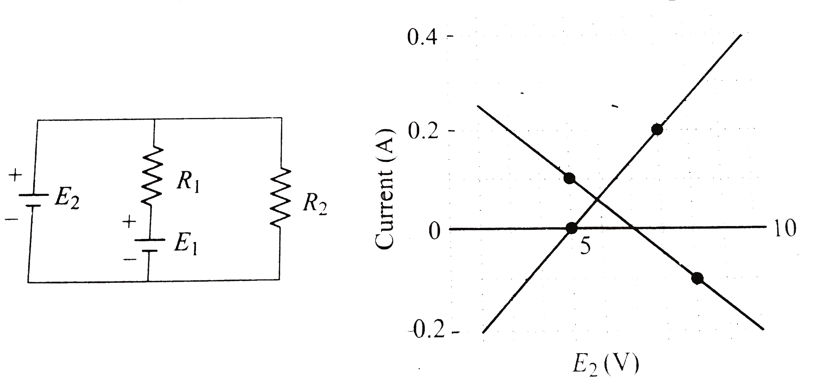
The value of emf `E_1` is
View Solution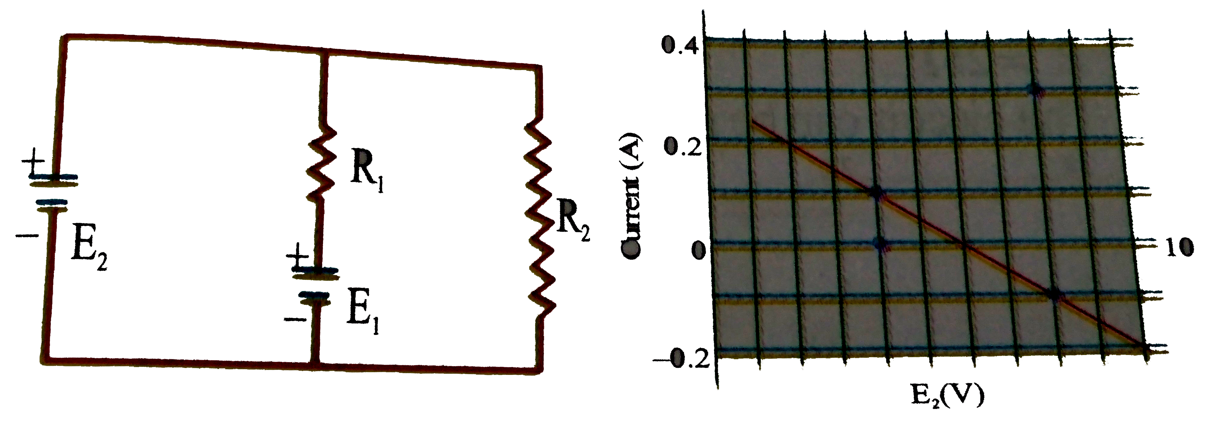
In the circuit givenn below, both batteries are ideal. EMF `E_(1)` of battery 1 has a fixed value but emf `E_(2)` of battery 2 can be varied between 1.0 V and 10.0 V the graph gives the currents through the two batteries as a function of `E_(2)`, but are not marked as shown plot corresponds to which battery. but both plots, current is assumed to be negative when the direction of the current through the battery is opposite the direction of that battery's emf. (direction of emf is from negative to positive).
Q. The resistance `R_(1)` has value
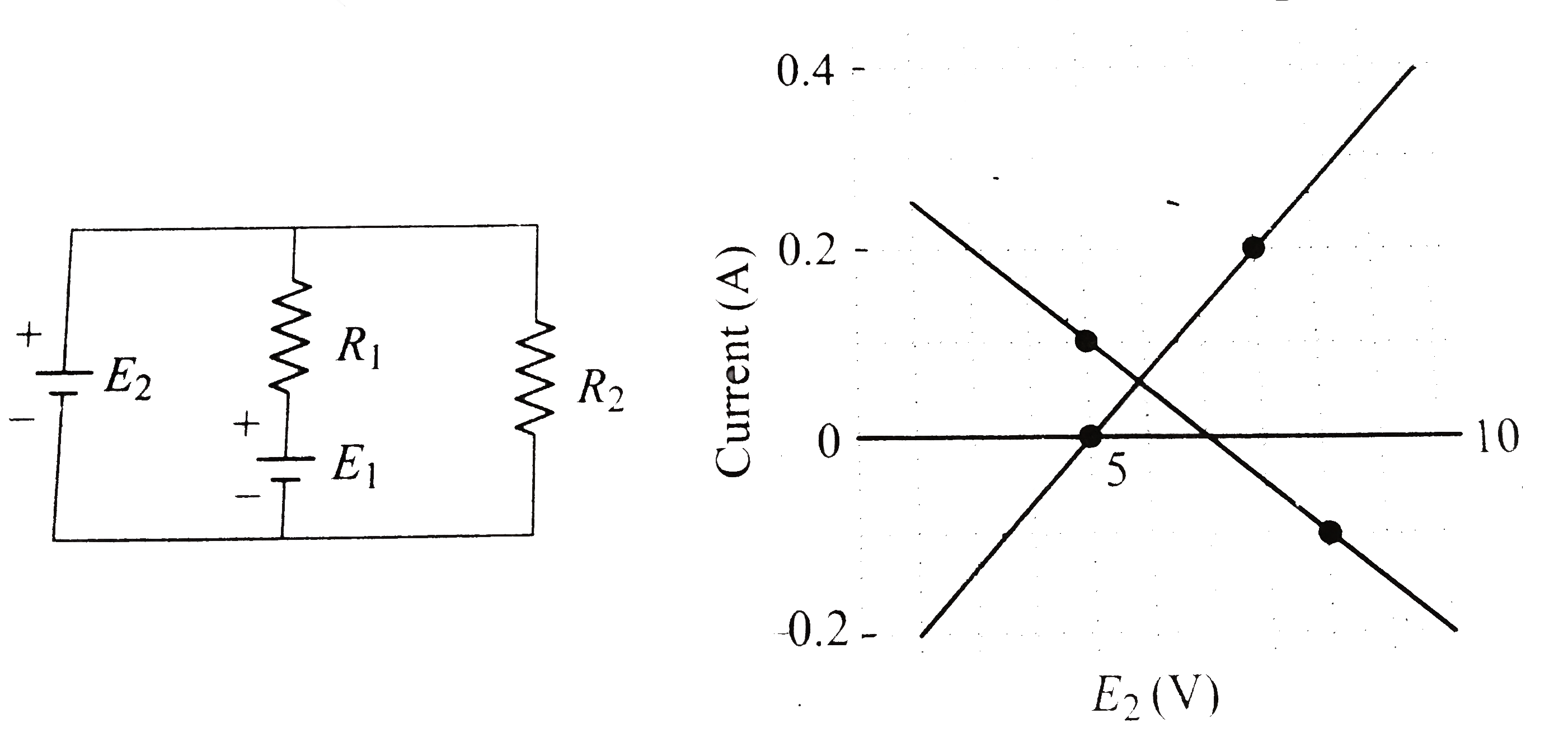
View SolutionIn the circuit given in the figure, both batteries are ideal . Emf `E_1` of battery 1 has a fixed value, but emf `E_2` of battery 2 can be varied between `1.0V and 10.0 V` . The graph gives the currents through the two batteries as a function of `E_2` but are not marked as which plot corresponds to which battery. But for both plots, current is assumed to be negative when the direction of the current through the battery is opposite to the direction of that battery's emf (direction of emf is from negative to positive.)
 ,
,
The resistance `R_2` is equal to
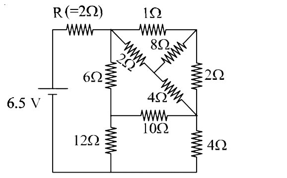
View SolutionIn the following circuit, the current through the resistor `R (=2Omega)` is I amperes. The value of I is
View Solution
Level 5 questions and complete solutions for chapter CURRENT ELECTRICITY of NARAYANA PHYSICS (HINGLISH) of Class 12