Complete Solutions to Level 6 of chapter CURRENT ELECTRICITY of Class 12 book with complete answers and questions
| Class 12 | PHYSICS |
| Chapter | CURRENT ELECTRICITY |
| NARAYANA | Level 6 |
| Number Of Questions | 43 |
| Academic Year | 2023-24 |

A steady current flows through the conductor of variable cross-sectional area. Now select the correct options.
View SolutionSelect the correct statement(s)
View SolutionTwo conducting layers of length `L` each specific resistivites `rho_(1)` and `rho_(2)` and cross-sectional areas `A_(1)` and `A_(2)` respectively are connected to a voltage source `V` such that current flow lines do not cross from one layer to the other.
(i). Find the total current in the system and describe how it is divided between the 2 layers
(ii). Find the total current when a third layer of cross-sectional area `A_(1)+A_(2)`, length `L` and specific resistivity `rho_(3)` is attached at one of the ends of the given system.
View Solution
A dc source with internal resistance `R_(0)` is loaded with three identical resistance R as shown in the figure. At what value of R will the thermal power generated in this circuit be the highest?
View SolutionWhat amount of heat will be generated in a coil of resistance `R` due to a charge q passing through it if the current in the coil
a. decreases down to zero uniformly during a time interval `t_0`?
b. decrases down to zero having its value every `t_0` seconds?
View SolutionWhat amount of heat will be generated in a coil of resistance `R` due to a charge q passing through it if the current in the coil
a. decreases down to zero uniformly during a time interval `t_0`?
b. decrases down to zero having its value every `t_0` seconds?
View Solution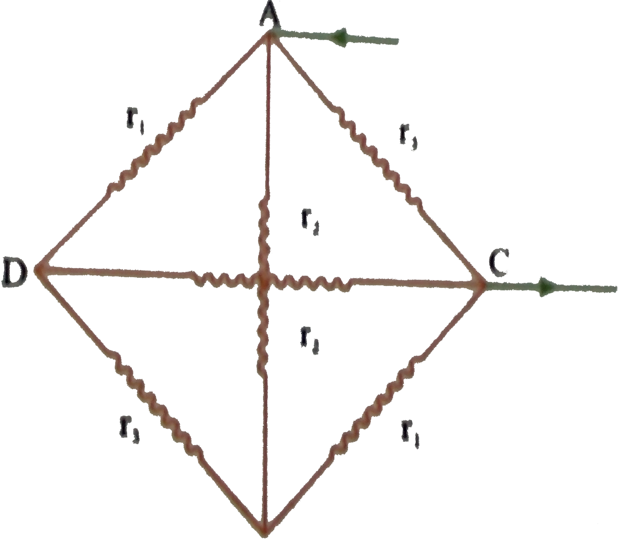
Six resistors are connected so as to form the edges of a tetrahedron ABCD, the resistances of opposite pairs being equal. (Note that the resistors AB and CD do not touch each other) find the equivalent resistance between A and C.
View Solution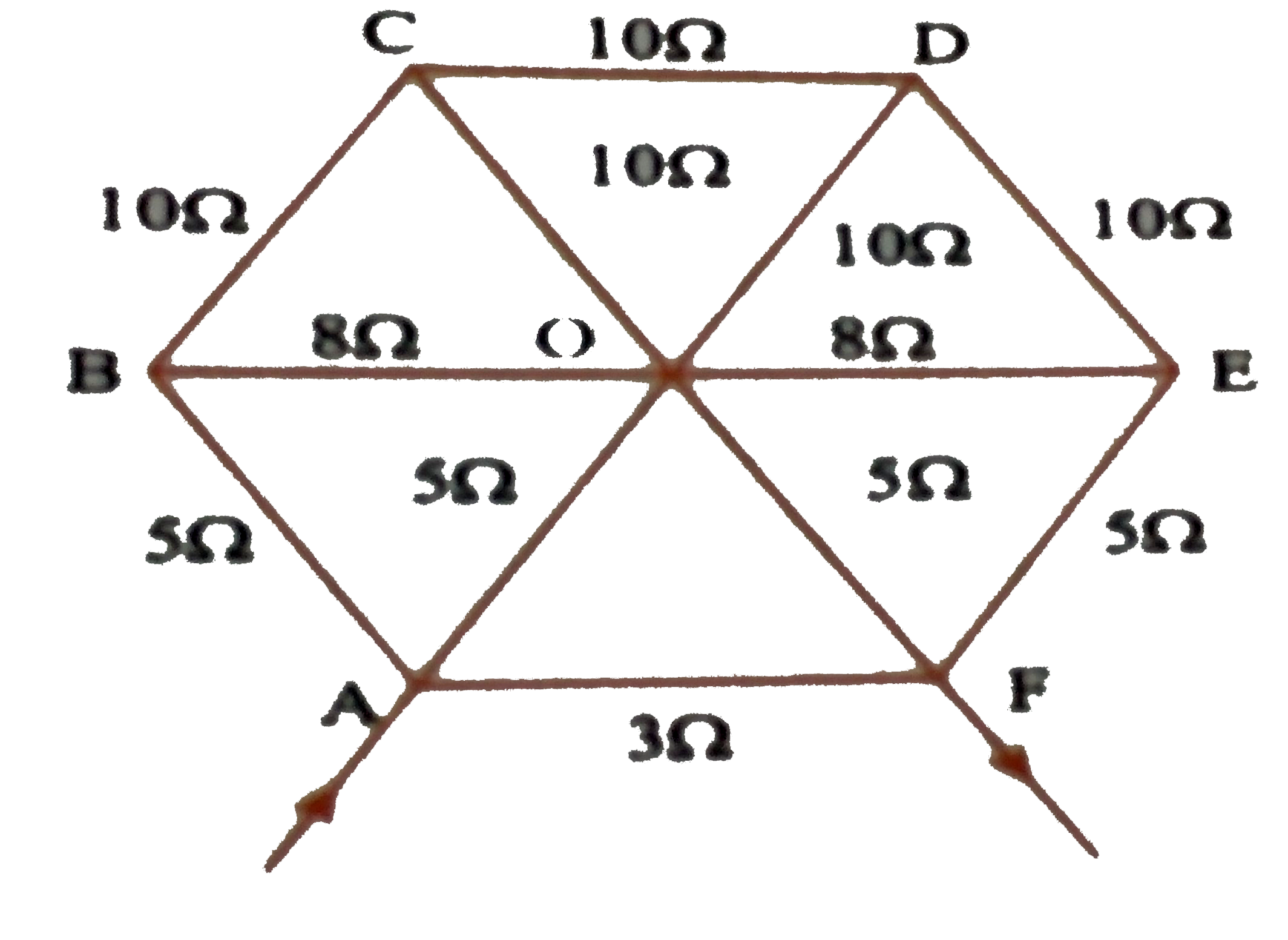
12 wires of different resistances are connected as shown. Find the equivalent resistance A and F.
View Solution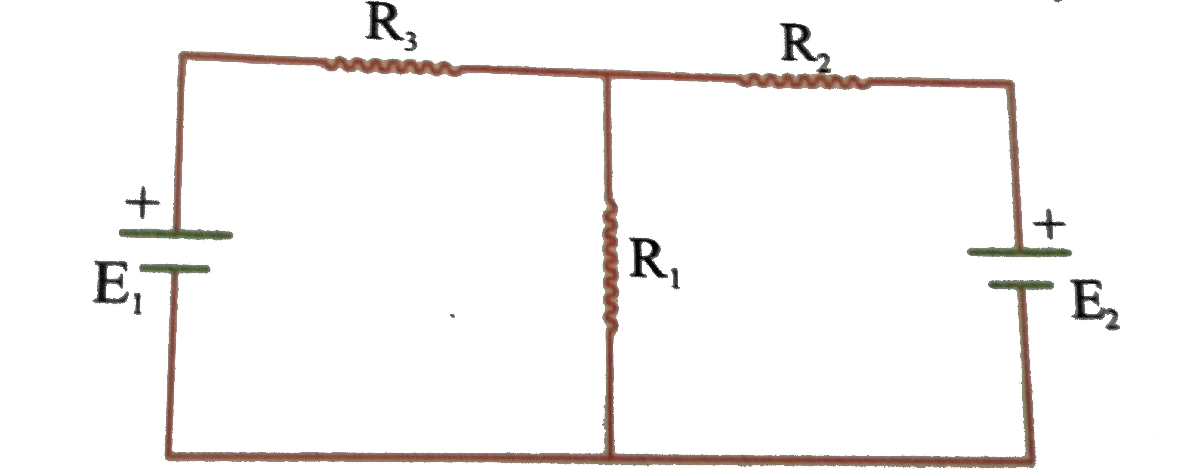
In the electrical network, shown in the diagram `R_(1)=5Omega,R_(2)=2Omega,R_(3)=3Omega` and `E_(1)=2E_(2)=10V`, sources have negligible internal resistance. For this network,
View Solution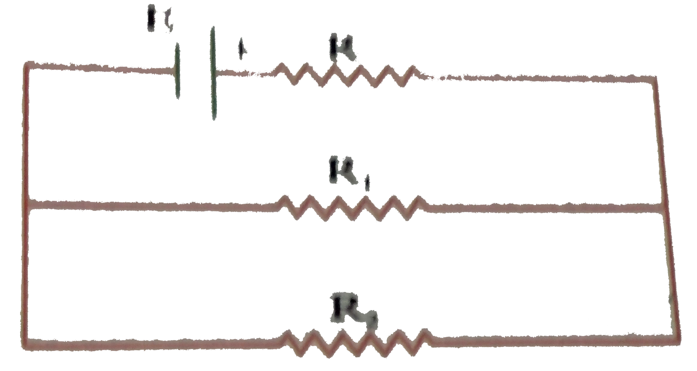
In the given network, the powers generated in the resistor `R_(1)` and `R_(2)` are `P_(1)` and `P_(2)` and the power generated in `R` is P. For this network.
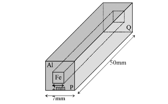
View SolutionIn an aluminium (Al) bar of square cross section, a square hole is drilled and is filled with iron (Fe) as shown in the figure. The electrical resistivities of Al and Fe are `2.7 xx (10^-8) Omega m and 1.0 xx (10^-7) Omegam,` respectively. The electrical resistance between the two faces P and Q of the composite bar is
View SolutionConsider two identical galvanometers and two identical resistors with resistance `R`. If the internal resistance of the galvanometers `R_(c) lt R//2`, which of the following statement(s) about any one of the galvanometers is (are) true?
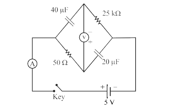
View SolutionIn the circuit shown below, the key is pressed at time t = 0 . Which of the following statements (s) is (are) true?
View SolutionFive `1 Omega` resistance are connected as shown in the figure. The resistance in the conneting wires is negligilbe. The equivalent resistance between `A` and `B` is

View Solution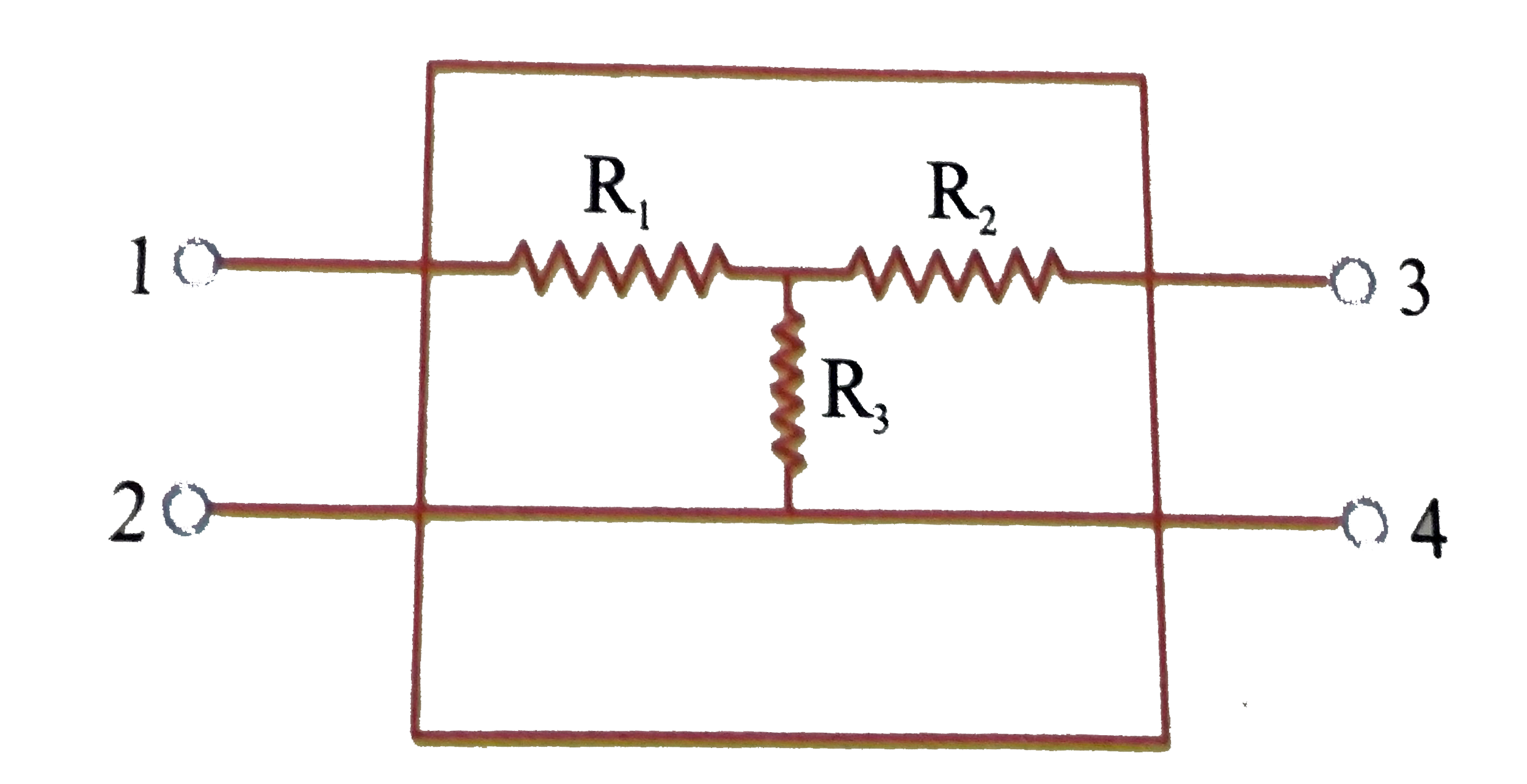
If voltage is applied between terminals 1 and 2 when terminals 3 and 4 are open the power liberated is `P_(1)=40W` and when terminals 3 and 4 are connected, the power liberated is `P_(2)=80W`. If the same source is connected to the terminals 3 and 4, the power liberated in the circuit when terminals 1 and 2 are open in `P_(3)=20W`. Determine the power `P_(4)` consumed in the circuit when the terminals 1 and 2 are connected and the same voltage is applied between the terminals 3 and 4.
View SolutionA storage battery with emf `epsilon=2.6V` loaded with an external resistance produces a currnet `I=1.0A` in this case the potential current `I=1.0A`. In this case the potential difference between the terminals of the battery is `V-=2.0V` now
View SolutionTwo batteris of emf `epsilon_(1)` and `epsilon_(2)` wit respective internal resistance `r_(1)` and `r_(2)` are connected in parallel. Now
View Solution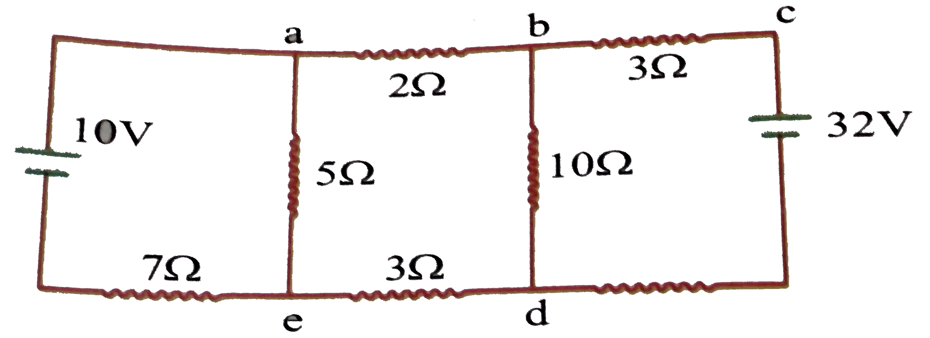
In the circuit diagram shown in the figure,
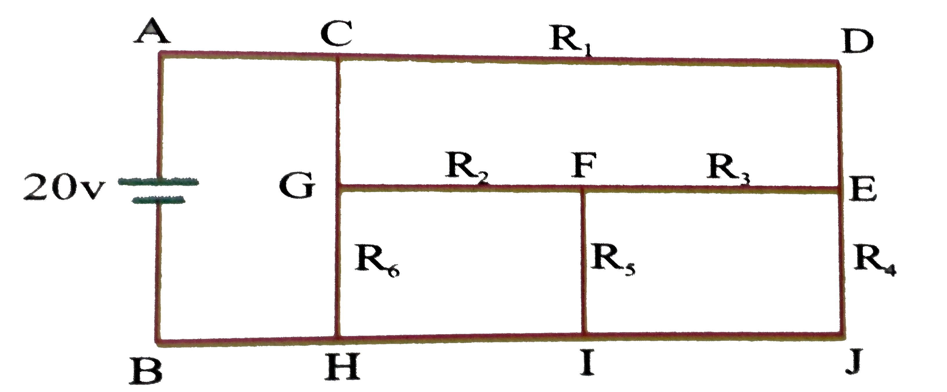
View SolutionIn the given circuit the resistance of all the resistors is equal to `2Omega`, find the current flowing through each resistor under steady state. Select the correct options.
View Solution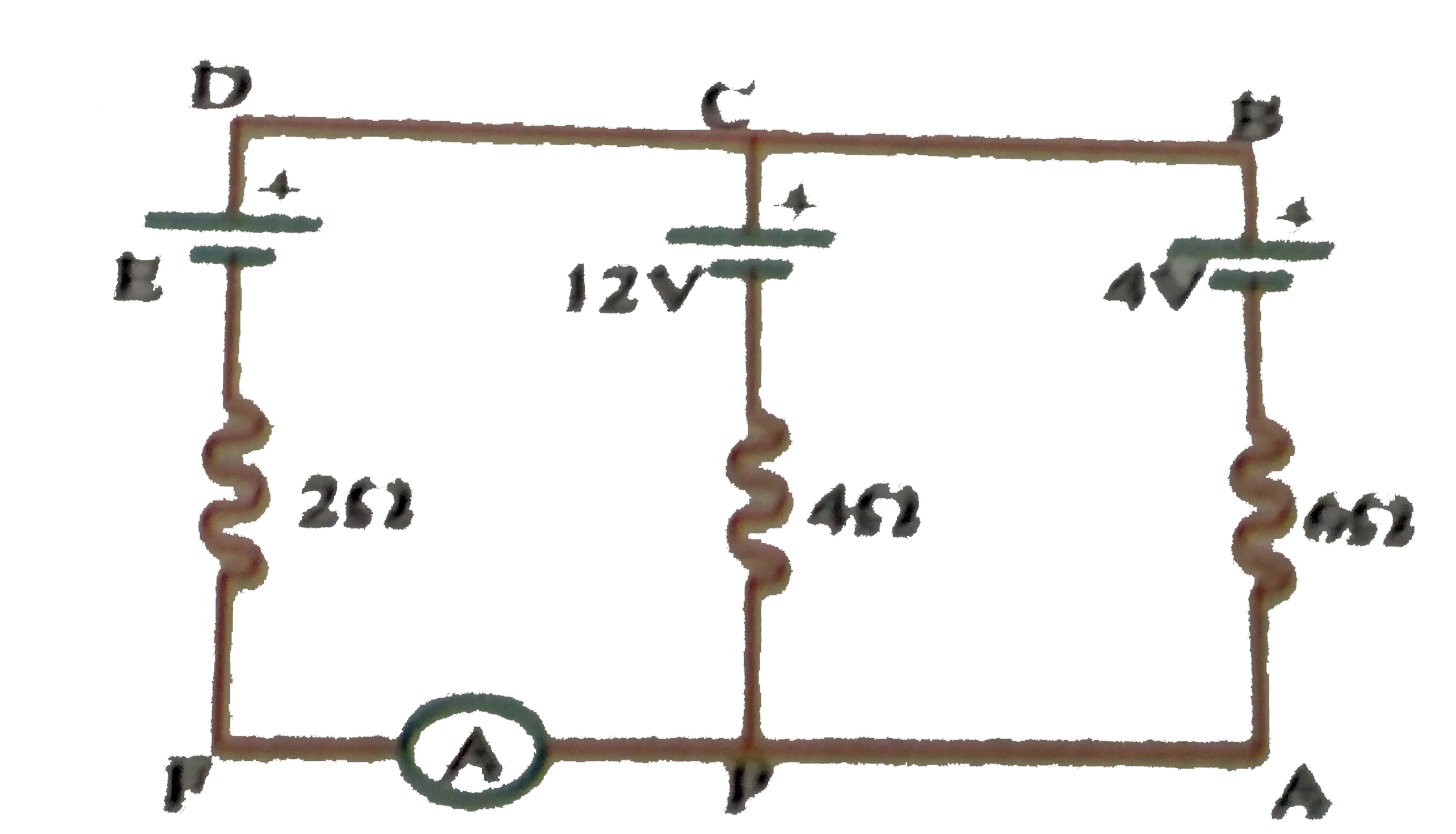
ABCDFPA is a network of three batteries of the e.m.f's E, 12 V and 4 V respectively and three resistance `2Omega,4Omega` and `6Omega` connected as shown in the diagram. An ideal ammeter connected between F and P shows a current reading of 0.5 A. Then the value of the e.m.f. E is
View SolutionIn a metere bridge, the wire consists of two parts one of length 30 cm and of radius r and the other of radius 2r. Where will the null point occur if the resistance in the left and right gaps are `5Omega` and `8Omega` respectively? The material of the wires is the same.
View Solution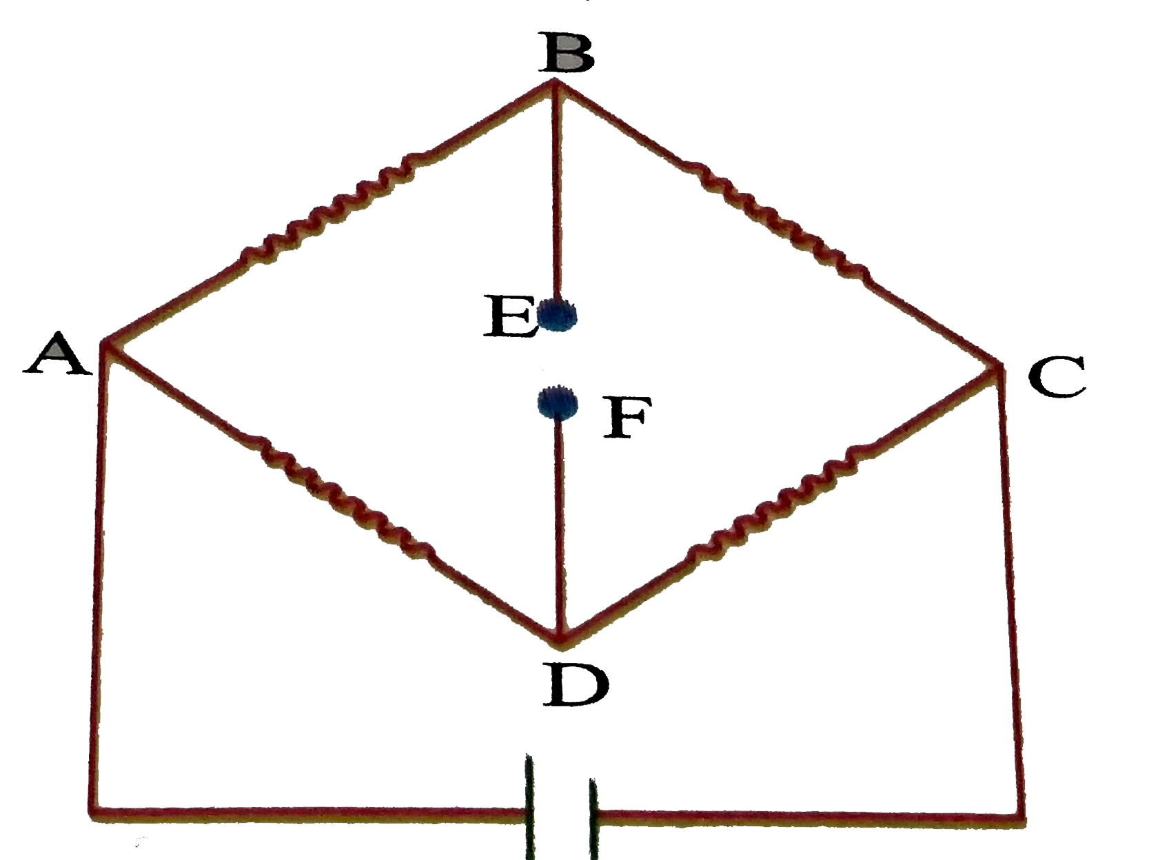
When an ideal voltmeter is connected between the [points E and F the reading of the meter is `V_(0)`. When an ideal ammeter is connected between E and F, reading is `I_(0)` find the current I through resistor R connected between E and F.
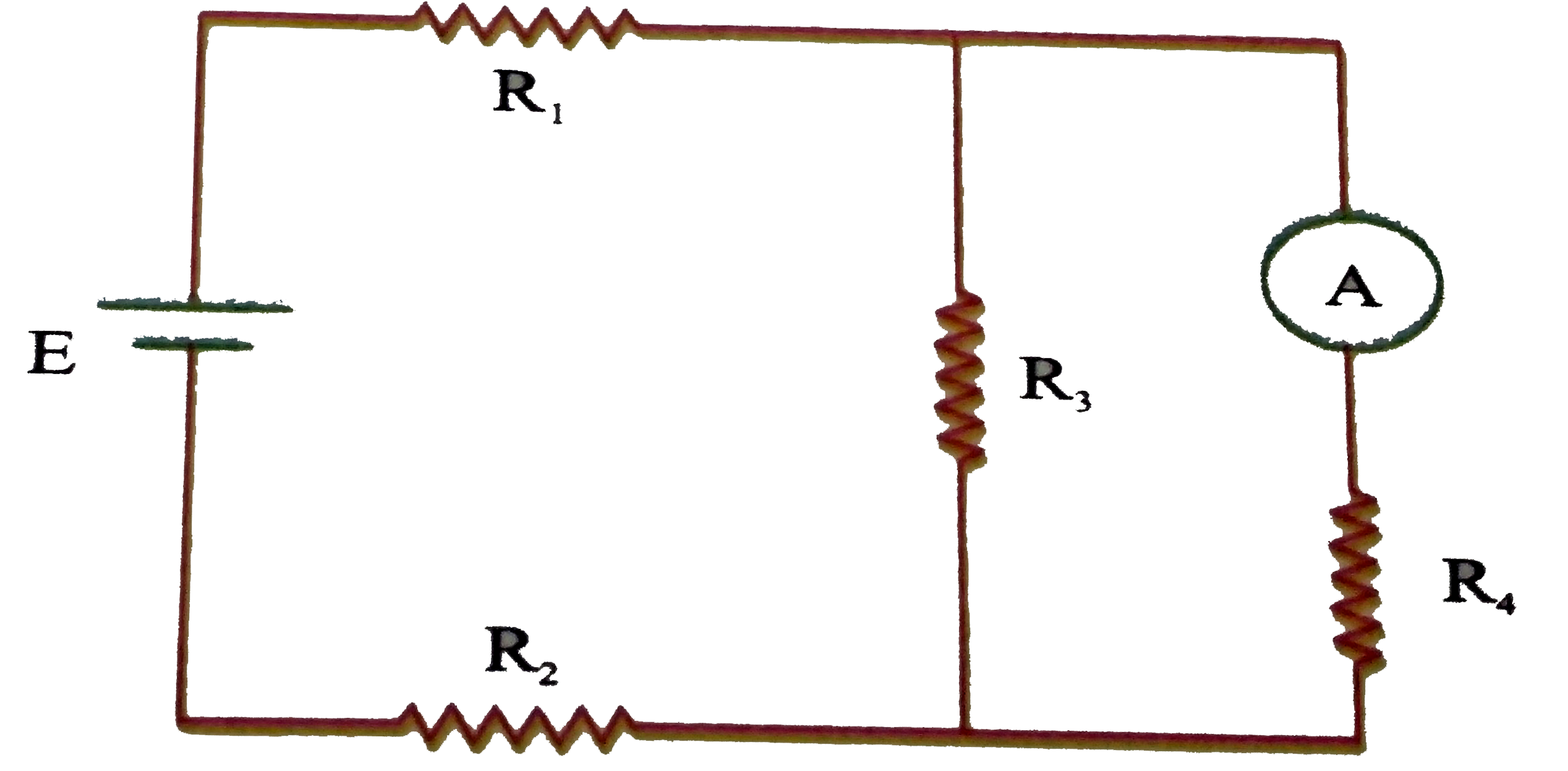
View SolutionA network of four unequal resistor `R_(1),R_(2),R_(3)` and `R_(4)` are connected in a network (see diagram) that contains a source of e.m.f E and an ammeter A. The source has negligible internal resistance. For this network,
View SolutionA galvanometer with a coil resistance of `100Omega` shows a full-scale deflection when a current of 1 mA is passed through it. What is value of the resistance which can convert this galvanometer into an ammeter showing a full scale deflection for a current 10 A? A resistance of the required value is available but it will get burnt if the energy dissipated in it is greater then 1 W. Can it be used for the conversion of the galvanometer described above?
View SolutionWhen the modified galvanometer of previous question is connected across te terminal of a battery, it shows a current of 4A. The current drops to 1A When resistance of `1.5Omega` is connected in series withh the modified galvanometer. Find the emf and the internal resistance of the battery.
View SolutionAn ammeter and a voltmeter are connected in series to a battery of emf `E=6.0V`. When a certain resistance is connected in parallel with the voltmeter, the readding of the voltmeter decreases two times, whereas the reading of the ammeter increases the same number of times. Find the voltmeter reading after the connection of the resistance.
View SolutionIt is required to measure the resistance of a circuit operating at `120 V`. There is only one galvanometer of current sensitivity `10^(-6)` A per division. How should the galvanometer be connected in the circuit to operate an ammeter? Why minimum resistance can be measured with such a galvanometer if its full-scale has `40` divisions?
View SolutionThe resistance of a potentiometer wire 8 m long is 8 ohm. A high resistance box and a 2-volt accumulator are connected in series with it. What should be the value of the resistance in the box, if it is desired to have a potential drop of 1 micro volt per mm?
View SolutionThe terminals of a cell are cnnected to resistance R and the falll of potential across R is balaced against the fall of potential on a potentiometer wire.When R is 20 `Omega` and 10 `Omega` respectively, the corresponding lengths of potentiometer wire are 1.5 m and 1.2 m Claculate the internal resistance of the cell
View SolutionAn accumulator of emf `2 V` and negligible internal resistance is connected across a uniform wire of length 10 m and resistance `30 Omega` The appropriate terminals of a cell of emf `1.5 V` and internal resistance `1 Omega` is connected to one end of the wire and the other terminal of the cell is connected through a sensitive galvanometer to a slider on the wire. What is the length of the wire that will be required to produce zero deflection of the galvanometer? How will the balancing length change?
(a) When a coil of resistance `5Omega` is placed in series with the accumulator.
(b) The cell of `1.5 V` is shunted with `5 Omega` resistor?
View SolutionA certain thermocouple (treat it as a seat of e.m.f) which has a total resistance of `10Omega` has one junction in melting ice and the other junction in melting ice and the other junction is steam. The e.m.f. between its ends as measured with a potentiometer is 4 millivolt. What would be its reading when it is connected to a milli volt meter which has a resistance of 50 ohm?
View SolutionA 10 m wire potentiometer has resistance `10Omega` and is connected to an accumulator of 2 volt and negligible internal resistance. There are two resistance boxes `R_(1)` and `R_(2)` is series with the accumulator and one can have any integral values of resistance from resistance boxes. A standard Cd-cell of 1.018 V having a sensitive galvanometer in series with it is connected across `R_(1)`. How would you proceed with the above arrangement to obtain a potential drop `1muV` per mm of the potentiometer wire? Calculate value of `R_(1)` and `R_(2)` required. What length of this potentiometer will balance the thermo e.m.f. of iron-copper couple at `300^(@)C` which develops `17muV//^(@)C`?
View SolutionA five wire potentiometer is connected to an accumulator of e.m.f 2.2 V and `1Omega` internal resistance. The potentiometer wire has resistance `1Omega` per metre. What is the maximum voltage that you can measure with this particular arrangement of potentiometer? What length of this potentiometer will balance the e.m.f of a daniell cell (e.fm.f `=1.18V`)? what resistance to balance this cell exactly at the centre of the last wire?
View SolutionA potentiometer wire of length 1000 cm has a resistance of 10 ohms. It is connected in series with a resistance and a cell of e.m.f 2 volts and of negligible internal resistance. A source of e.m.f 10 millivolts is balanced against a length of 40 cm of the potentiometer wire. What is the value of the external resistance?
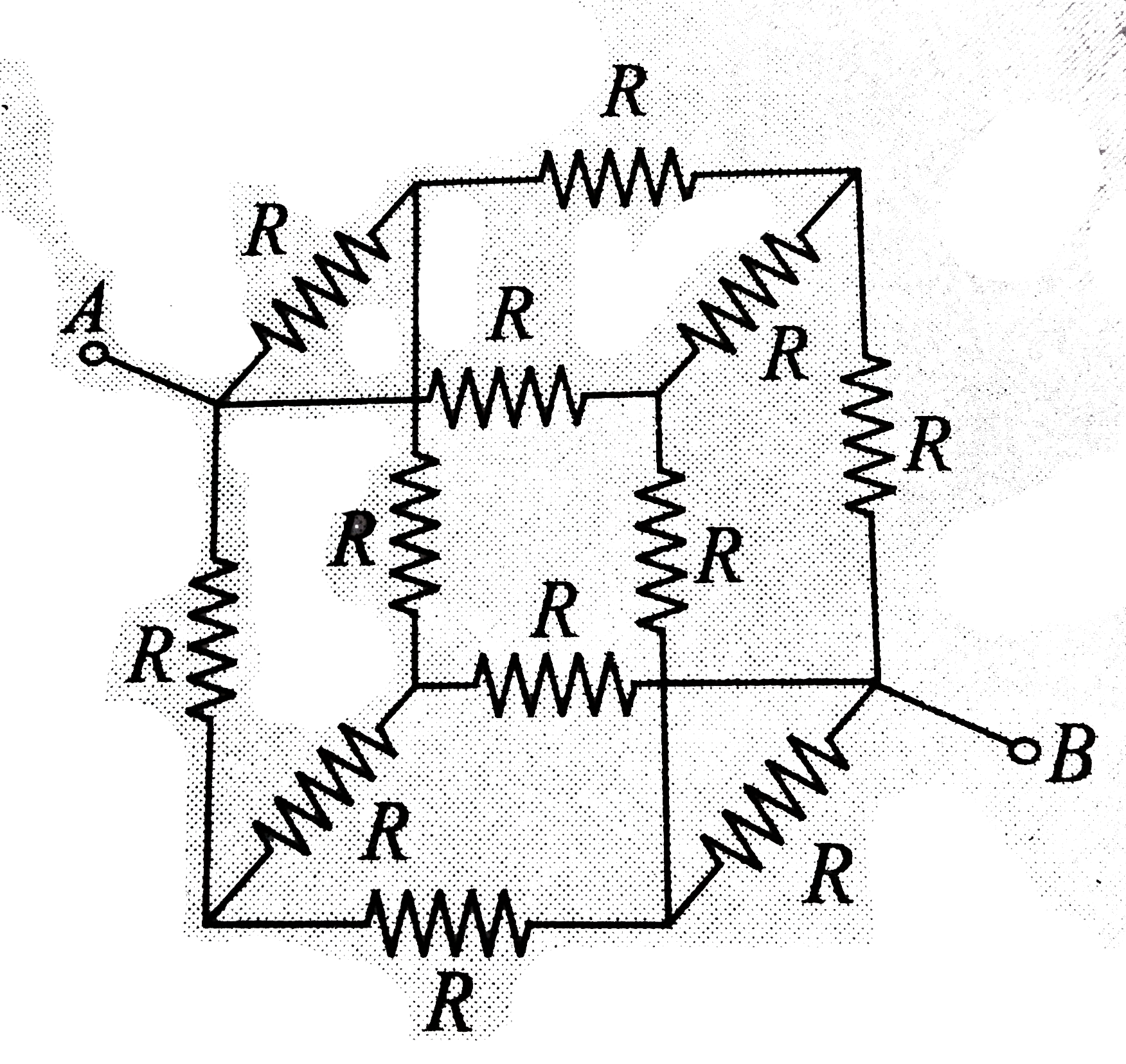
View SolutionTwelve identical resistances arranged on all edges of a cube. The resistors are all the same. Then find the equivalent resistance between the edges A and B as shown in figure.
View SolutionTwelve straight uniform wires of length `a` and resistance R are joined to form the edges of a cube of side `a`. Current enters the system at one corner andd leaves from a point on one of the edges meeting at the opposite corner at a distance `Ka(ltKlt1)` from it.
Q. The equivalent resistance is maximum, when
View SolutionTwelve straight uniform wires of length `a` and resistance R are joined to form the edges of a cube of side `a`. Current enters the system at one corner andd leaves from a point on one of the edges meeting at the opposite corner at a distance `Ka(ltKlt1)` from it.
Q. The maximum value of the equivalent resistance is
View Solution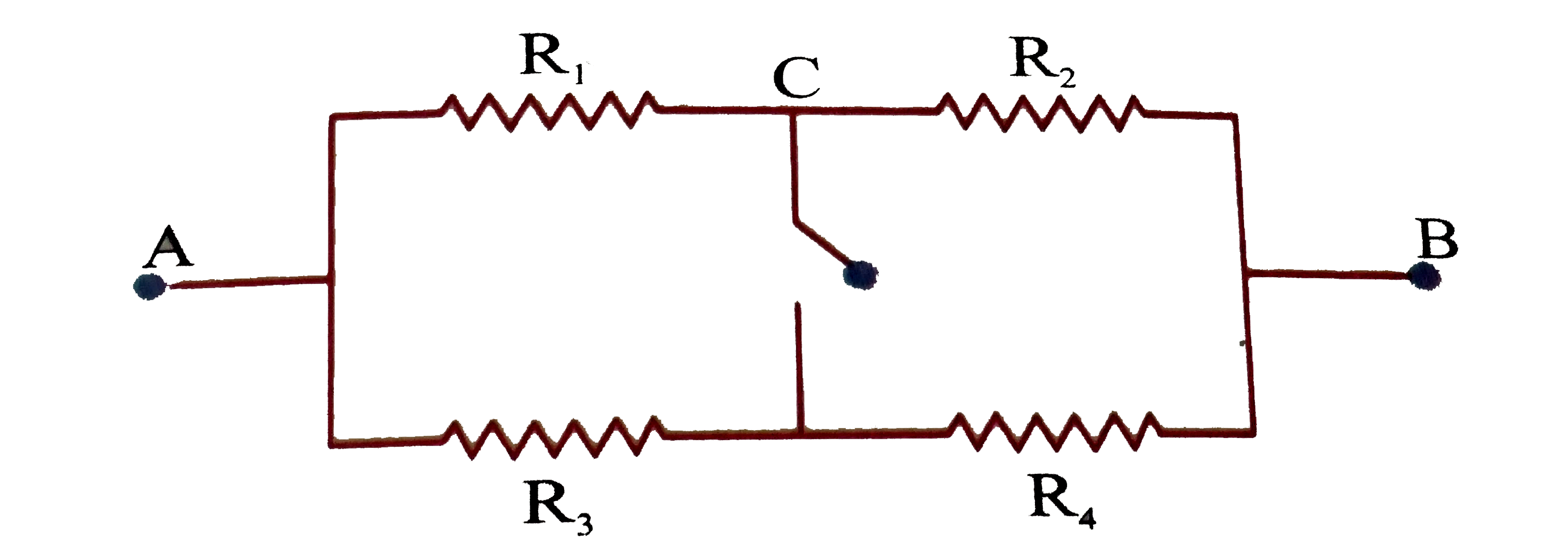
Four resistors `R_(1),R_(2),R_(3)` and `R_(4)` are connected between two terminals A and B iin a network as shown in the diagram. A key K can connect the two points (see diagram) C and D. A constant potential difference `(V_(A)-V_(B))=V` is maintained between thhe points A and B
Q. If `V=25,R_(1)=1Omega,R_(2)=2Omega,R_(3)=3Omega` and `R_(4)=4Omega` the current that will flow from C to D on connecting key K is
View Solution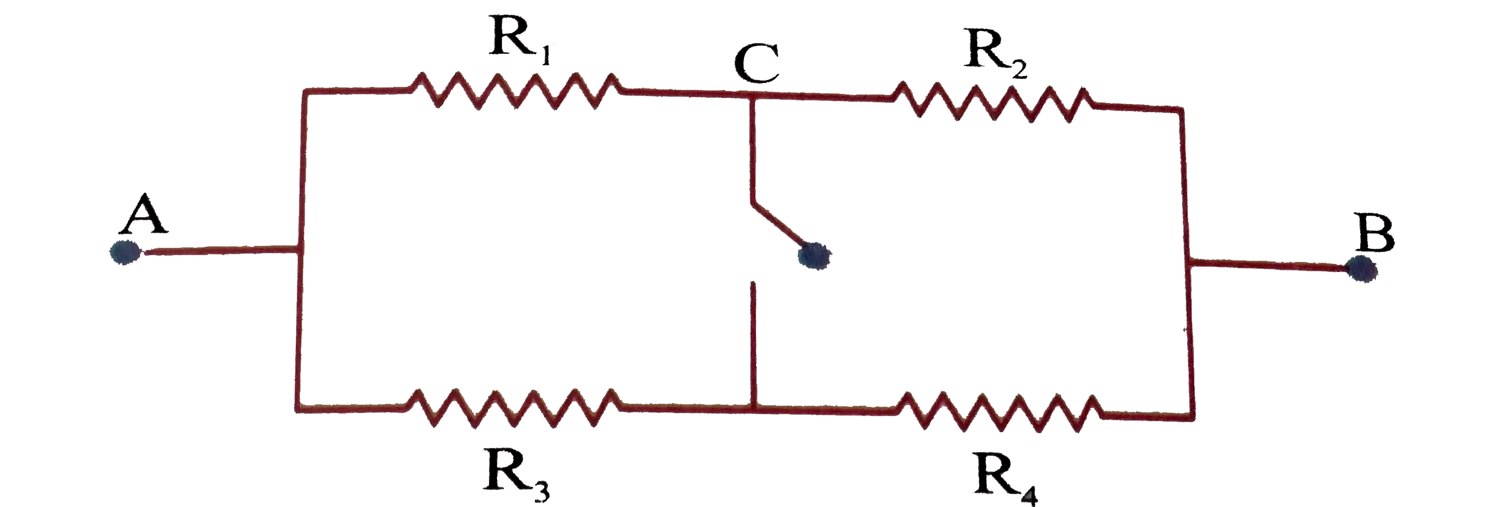
Four resistors `R_(1),R_(2),R_(3)` and `R_(4)` are connected between two terminals A and B iin a network as shown in the diagram. A key K can connect the two points (see diagram) C and D. A constant potential difference `(V_(A)-V_(B))=V` is maintained between thhe points A and B
Q. In on connecting the key K, no current flows through the segment CD, whatever potential difference V exists between A and B which of the following cases will satisfy this condition?
View Solution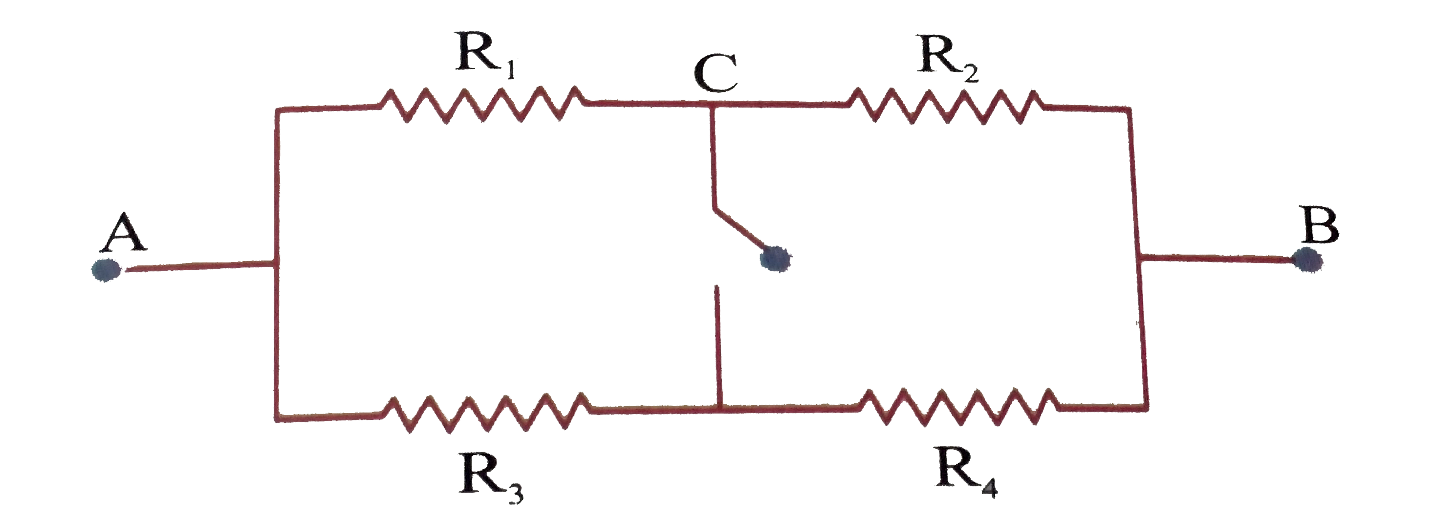
Four resistors `R_(1),R_(2),R_(3)` and `R_(4)` are connected between two terminals A and B iin a network as shown in the diagram. A key K can connect the two points (see diagram) C and D. A constant potential difference `(V_(A)-V_(B))=V` is maintained between thhe points A and B
Q. If `R_(1)=R_(4)=1Omega` and `R_(2)=R_(3)=2Omega`, the effective resistance between the terminals A and B will change, on closing the key K, by
View Solution
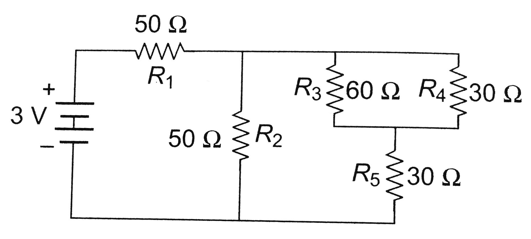
In the circuit shown, the resistances are given in ohms and the battery is assumed ideal withh emf equal to 3.0 volts.
Q. The resistor that dissipates maximum power
View SolutionIn circuit shown below, the resistance are given in ohms and the battery is assumed ideal with emf equal to 3 volt The voltage across the resistance `R_(4)` is
View Solution
In the circuit shown, the resistances are given in ohms and the battery is assumed ideal withh emf equal to 3.0 volts.
Q. The current passing through 3 V battery is
View Solution
Level 6 questions and complete solutions for chapter CURRENT ELECTRICITY of NARAYANA PHYSICS (HINGLISH) of Class 12