The resistance each of 16Ω and capacitance of each 100μF are arranged as shown in the figure. A battery of emf 12V is joined across A and B. Find the
(i) reading of the ammeter just after key is ciosed and after long time.
(ii) charges in each capacitors when steady state is achieved.
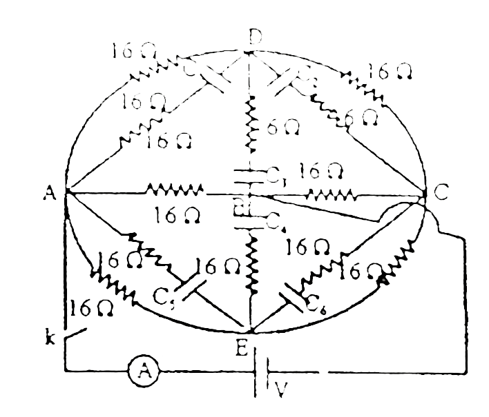
(i) Just after the key is closed
The circuit will be as shown in figure 1
Then circuit can be simplify as figure 2
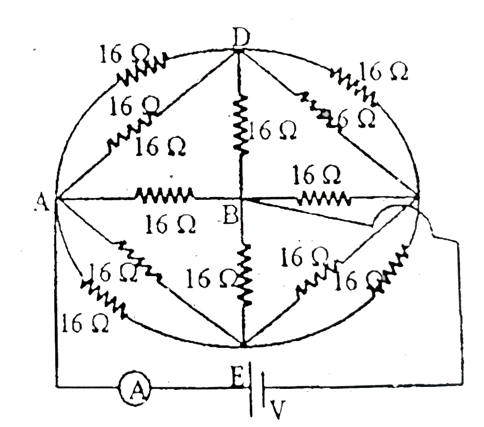
The points D and E will be at same potential hence the circuit can be further simplified as shown in figure 3 & 4

Hence equivalent resistance across A and B, Req=687×16687+16=6.04Ω
Hence reading of ammeter I=126.4≈2A.
After long time the circuit can be redrawn as
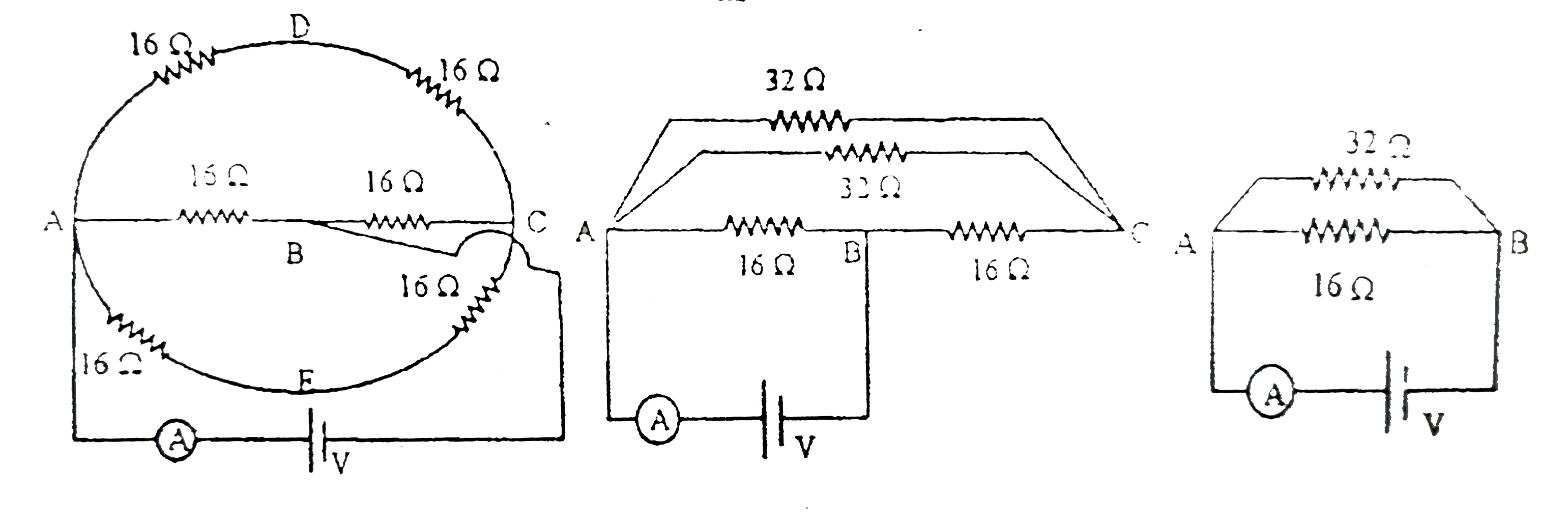
RAB=16×3216+32=323Ω
Hence the reading of the ammeter I=98A
(ii) The current through paths ADC and AEC will be same and will be equal to
I2=12xX98×1648=316A
Hence potential difference across AD, AE, DC and CE, V'=16×316=3V
Hence the charge in the C1, C2, C5 and C6q=100×3=300μC
Also VDB=VEB=12−3=9V
Hence the charge in the capacitor C3 and C4=100×9=900μC
Topper's Solved these Questions
- BOOK - FIITJEECHAPTER - GMP ASSESMENTEXERCISE - Objective problems215videos
GMP ASSESMENT
- BOOK - FIITJEECHAPTER - GMP ASSESMENTEXERCISE - Assertion & Reason15videos
GMP ASSESMENT
- BOOK - FIITJEECHAPTER - GENERAL PHYSICSEXERCISE - MATRIX MATCH TYPE3videos
GENERAL PHYSICS
- BOOK - FIITJEECHAPTER - GRAVITATIONEXERCISE - Numerical based Question2videos
GRAVITATION
Similar Questions
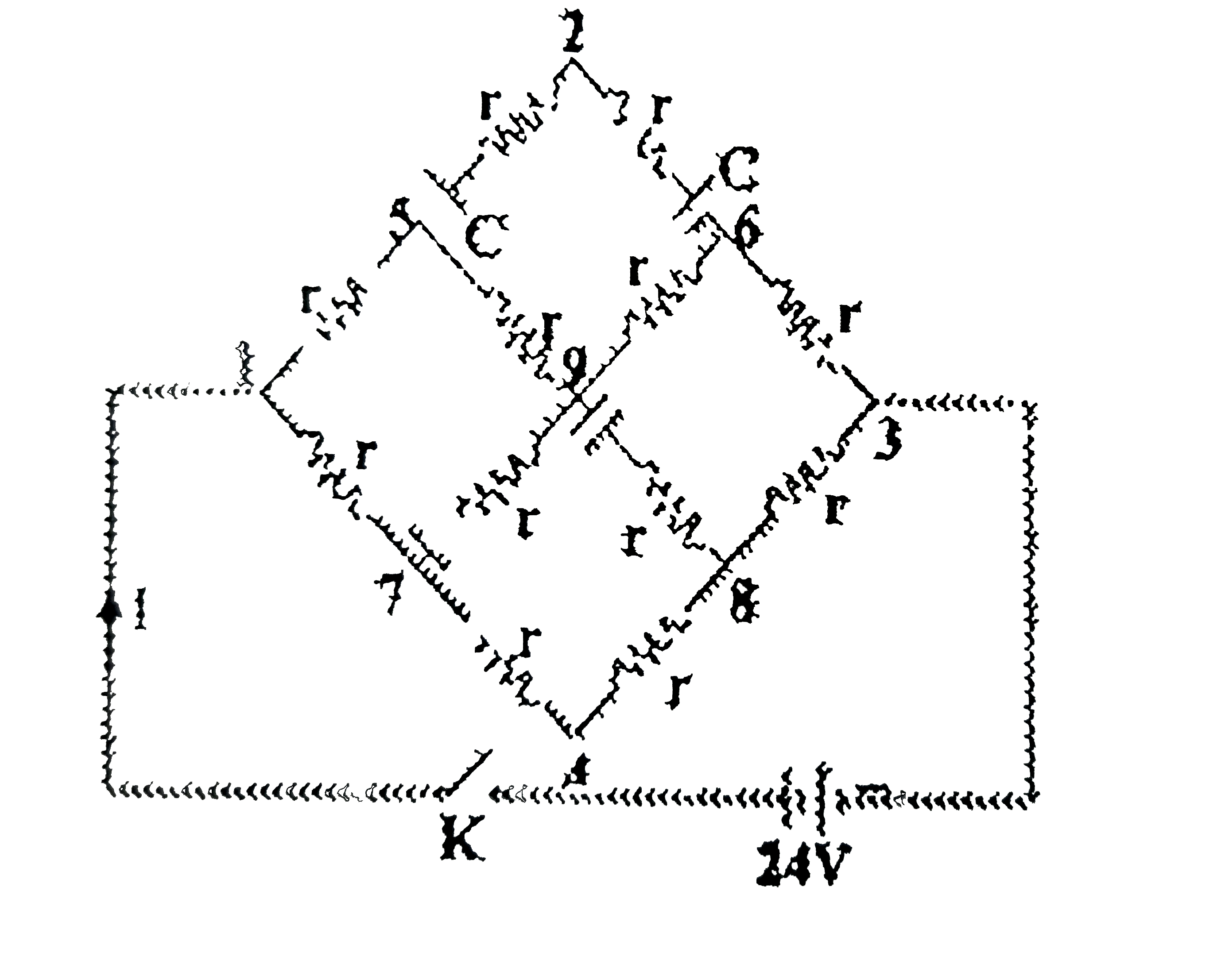
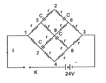
In the circuit shown, r=4Ω, C=2μF
(a) Find the current coming out of the battery just after the switch is closed.
(b) Find charge on each capacitor in the steady state condition.
 View Solution
In the circuit shown, r=4Ω, C=2μF
(a) Find the current coming out of the battery just after the switch is closed.
(b) Find charge on each capacitor in the steady state condition.
 View Solution
Knowledge Check
- Question 1 - Select One
Seven resistances, each of value 20Ω, are connected to a 2 V battery as shown in the figure. The ammeter reading will be
 A1/10 AB3/10 AC4/10 AD7/10 A.
 - Question 2 - Select One
Four capacitors each of 8μF, are joined as shown in the figure. The equivalent capacitance between the points A and B is
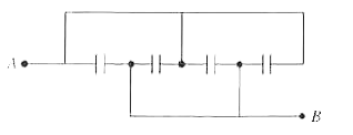 A32μFB2μFC8μFD16μF
 - Question 3 - Select One
n resistances each of resistance R are joined with capacitors of capacity C (each) and a battery of emf E as shown in the figure. In steady state condition ratio of charge stored in the first and last capacitor is :
 An:1B(n−1):(n+1)C(n2+1):(n2−1)D1:1
In the circuit shown, r=4Ω,C=2μF
(a) Find the current coming out of the battery just after the switch is closed
(b) Find charge on each capacitor in the steady state condition
 View Solution
A capacitor of capacitance 100(μ)F is charged by connecting it to a battery of emf 12 V and internal resistance 2(Ω). (a) Find the time constant of the circuit. (b) Find the time taken before 99% of maximum charge is stored on the capacitor.
View SolutionA capacitor of capacitance 100(μ)F is charged by connecting it to a battery of emf 12 V and internal resistance 2(Ω). (a) Find the time constant of the circuit. (b) Find the time taken before 99% of maximum charge is stored on the capacitor.
View SolutionA capacitor of capacitance 100(μ)F is charged by connecting it to a battery of emf 12 V and internal resistance 2(Ω). (a) Find the time constant of the circuit. (b) Find the time taken before 99% of maximum charge is stored on the capacitor.
View Solutionn resistances each of resistance R are joined with capacitors of capacity C (each) and a battery of emf E as shown in the figure. In steady state condition ratio of charge stored in the first and last capacitor is :
 View Solution

