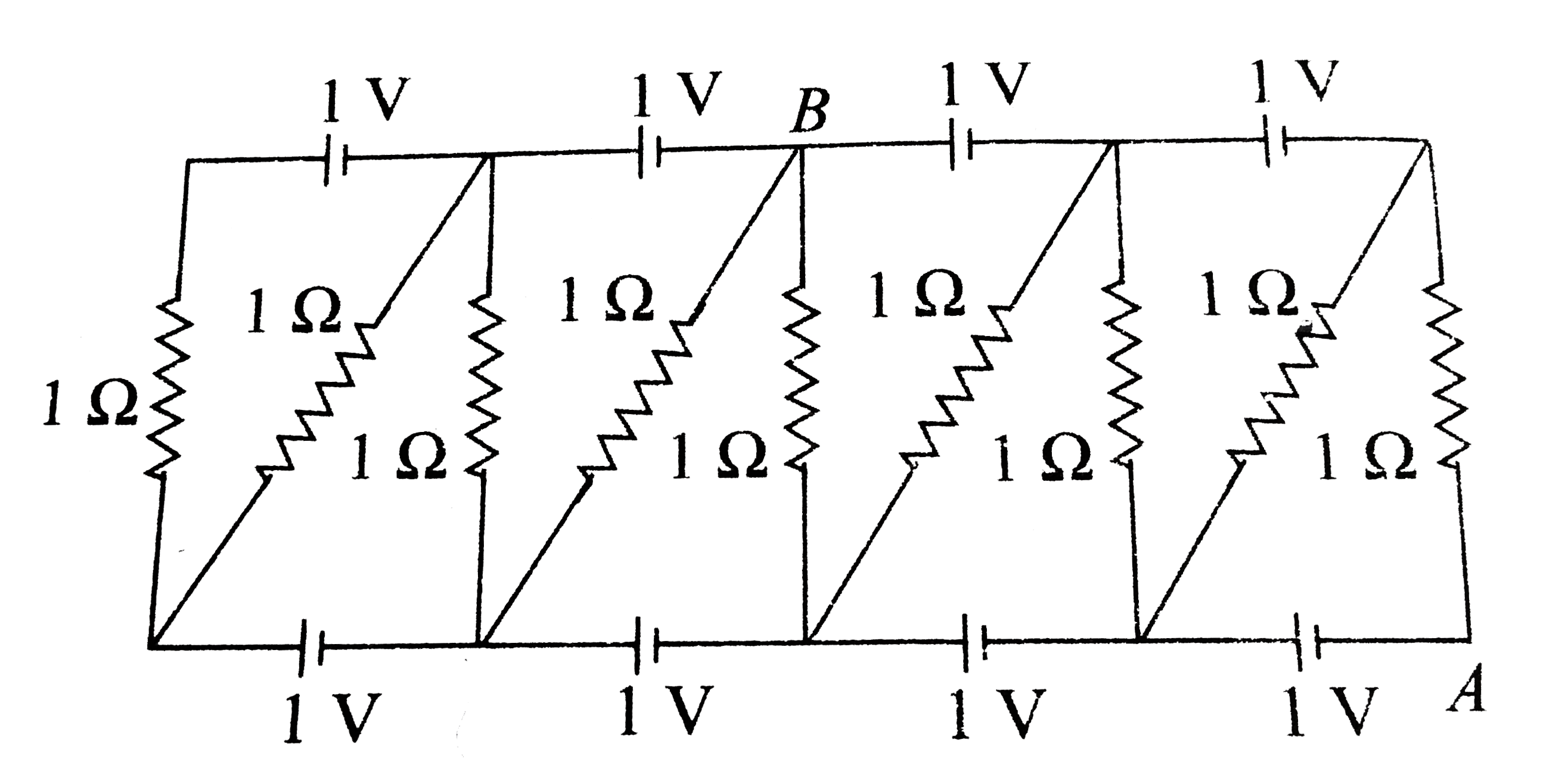
Calculate for the following circuit.

Text Solution
We can see symmetry in upper half and lower half of the circuit. Let I be the current in upper half as well as in lower. Middle branch carries 2I current. Applying Kirchhoff.s law in loop DBAD: …(i)
Let us write potential difference between A and B.
...(ii)
Substituting result obtained from equation (i) into equation (ii), we get
|
Topper's Solved these Questions
- CURRENT ELECTRICITYBOOK - MODERN PUBLICATIONCHAPTER - CURRENT ELECTRICITYEXERCISE - NCERT SOLVED (NCERT Textbook Exercises)
13 Videos
- CURRENT ELECTRICITYBOOK - MODERN PUBLICATIONCHAPTER - CURRENT ELECTRICITYEXERCISE - NCERT SOLVED (NCERT Additional Exercises)
11 Videos
- CURRENT ELECTRICITYBOOK - MODERN PUBLICATIONCHAPTER - CURRENT ELECTRICITYEXERCISE - CONCEPTUAL QUESTIONS
35 Videos
- ATOMS BOOK - MODERN PUBLICATIONCHAPTER - ATOMS EXERCISE - Chapter Practice Test
16 Videos
- DUAL NATURE OF RADIATION AND MATTER BOOK - MODERN PUBLICATIONCHAPTER - DUAL NATURE OF RADIATION AND MATTER EXERCISE - CHAPTER PRACTICE TEST
15 Videos
Similar Questions
Knowledge Check
The potential difference between the points V and B in the following circuit will be -
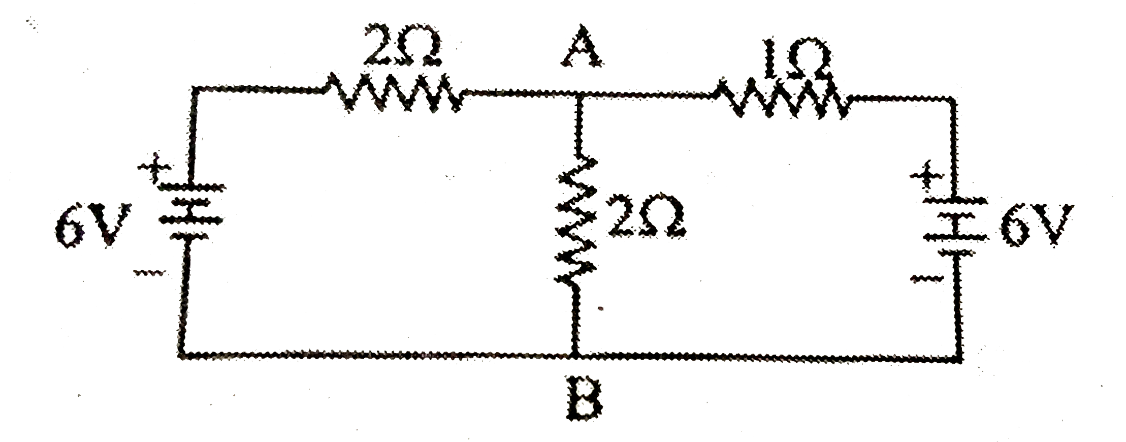 AzeroB2 VC3.5 VD4.5 V
VA and VB denote potential of A and B, then the equivalent resistance between A and B in the adjoining circuit is (ideal diode).
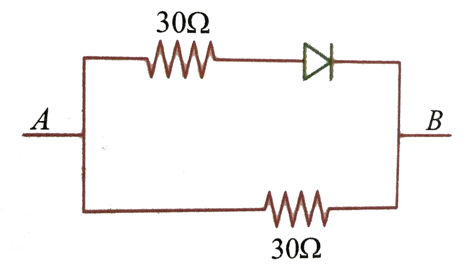 .A15ΩifVA>VBB30ΩifVA<VBCboth 1 and 2Dneither 1 nor 2
VAandVB denot potentils of A and B then the equivalent resistance of A and B, then the equivalent resistance between A and B in the adjoining circuit is (ideal diode)
 A15ΩifVA>VBB30ΩifVA<VBCboth 1 and 2Dneither 1 nor 2
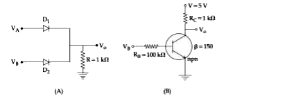
IF VAandVB are the input voltages (either 5 V or 0 V) and Vo is the output voltage then the two gates represented in the following circuits (A) and (B) are :
View SolutionGive the magnitude and polarity of the following voltages in the circuit of figure:
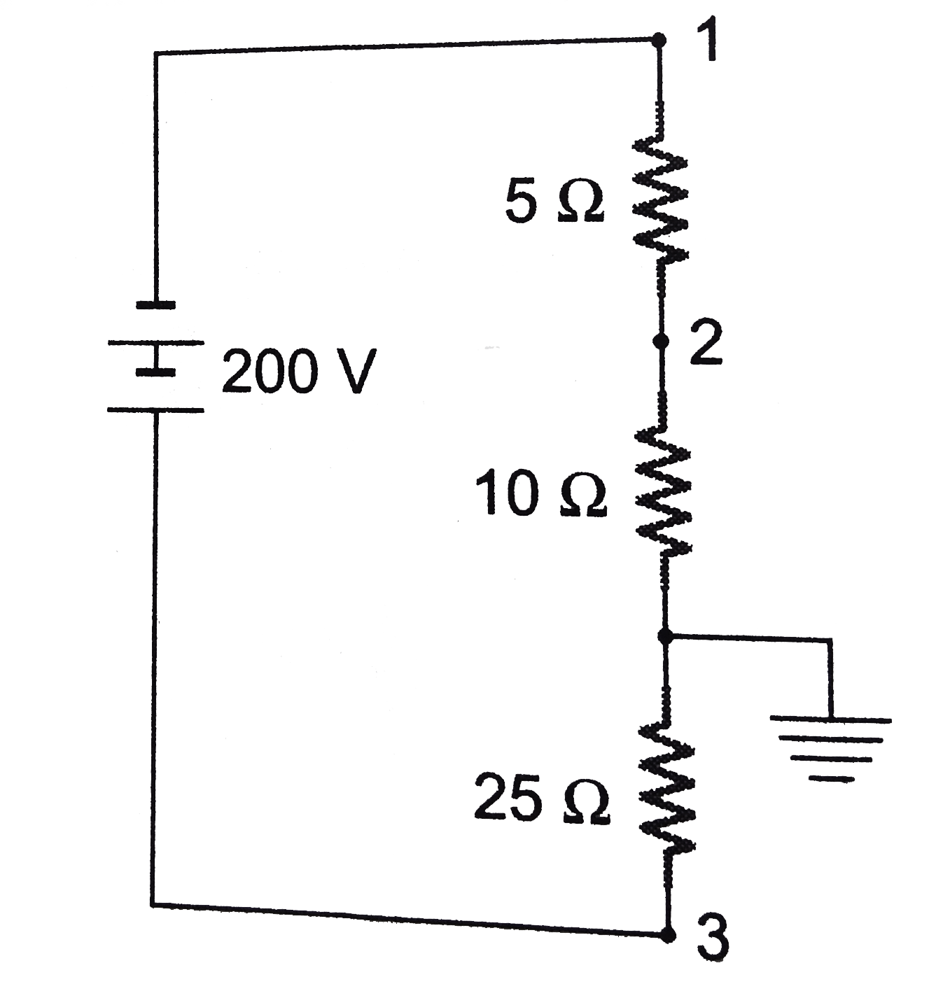
i. V1 ii. V2 iii. V3 iv. V3−2
v. V1−2
V1−3
View SolutionGive the magnitude and polarity of the following voltages in the circuit of figure:

i. V1 ii. V2 iii. V3 iv. V3−2
v. V1−2
V1−3
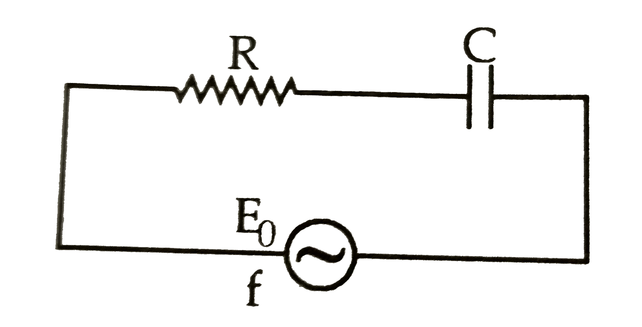
View SolutionIn the given L-R circuit, which of the following gives correct relation between V,VRandV?
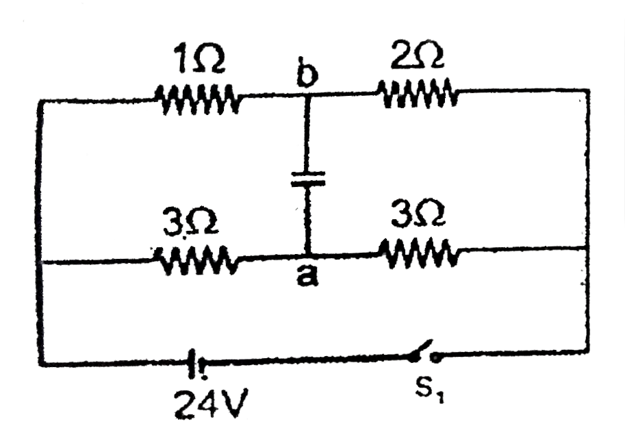
View SolutionFor the circuit shown in the diagram find the value of Va−Vb after long time closing the switch S1:
View Solution

