An emf of is applied in a circuit containing inductance and resistance. The ratio of the currents at time and is
The correct Answer is:B
To solve the problem, we need to find the ratio of the currents in an RL circuit at two different times: t=∞ and t=1s.
1. Identify the given values:
- EMF (V) = 15 V
- Inductance (L) = 5 H
- Resistance (R) = 10 Ω
2. Calculate the time constant (τ):
τ=LR=5H10Ω=0.5s
3. Determine the maximum current (I0):
The maximum current in the circuit when it reaches steady state (as t→∞) is given by:
I0=VR=15V10Ω=1.5A
4. Write the expression for current I(t) in the circuit:
The current as a function of time in an RL circuit is given by:
I(t)=I0(1−e−tτ)
5. Calculate the current at t=∞:
As t→∞:
I(∞)=I0(1−e−∞τ)=I0⋅1=1.5A
6. Calculate the current at t=1s:
Substitute t=1s into the current equation:
I(1)=1.5(1−e−10.5)=1.5(1−e−2)
Now, calculate e−2:
e−2≈0.1353(using a calculator)
Thus,
I(1)=1.5(1−0.1353)=1.5×0.8647≈1.297A
7. Find the ratio of the currents:
Now, we can find the ratio of the currents at t=∞ and t=1s:
Ratio=I(∞)I(1)=1.51.297≈1.157
Final Answer:
The ratio of the currents at t=∞ and t=1s is approximately 1.157.
- EMF (V) = 15 V
- Inductance (L) = 5 H
- Resistance (R) = 10 Ω
τ=LR=5H10Ω=0.5s
The maximum current in the circuit when it reaches steady state (as t→∞) is given by:
I0=VR=15V10Ω=1.5A
The current as a function of time in an RL circuit is given by:
I(t)=I0(1−e−tτ)
As t→∞:
I(∞)=I0(1−e−∞τ)=I0⋅1=1.5A
Substitute t=1s into the current equation:
I(1)=1.5(1−e−10.5)=1.5(1−e−2)
e−2≈0.1353(using a calculator)
Thus,
I(1)=1.5(1−0.1353)=1.5×0.8647≈1.297A
Now, we can find the ratio of the currents at t=∞ and t=1s:
Ratio=I(∞)I(1)=1.51.297≈1.157
The ratio of the currents at t=∞ and t=1s is approximately 1.157.
Topper's Solved these Questions
- BOOK - DC PANDEY ENGLISHCHAPTER - ELECTROMAGNETIC INDUCTIONEXERCISE - Medical entrance special format questions17videos
ELECTROMAGNETIC INDUCTION
- BOOK - DC PANDEY ENGLISHCHAPTER - ELECTROMAGNETIC INDUCTIONEXERCISE - Match the columns5videos
ELECTROMAGNETIC INDUCTION
- BOOK - DC PANDEY ENGLISHCHAPTER - ELECTROMAGNETIC INDUCTIONEXERCISE - Check point60videos
ELECTROMAGNETIC INDUCTION
- BOOK - DC PANDEY ENGLISHCHAPTER - CURRENT ELECTRICITYEXERCISE - Medical entrances gallery97videos
CURRENT ELECTRICITY
- BOOK - DC PANDEY ENGLISHCHAPTER - ELECTROMAGNETIC WAVESEXERCISE - Sec C22videos
ELECTROMAGNETIC WAVES
Similar Questions
An e.m.f. E=4cos(1000t)volt is applied to an LR circuit of inductance 3mH and resistance 4ohm. The amplitude of current in the circuit is
View SolutionAn alternating emf of 110 V is applied to a circuit containing a resistance R of 80Ω and an inductor L in series. The current is found to lag behind the supply voltage by an angle θ=tan1(3/4). Find the :
If the inductor has a coefficient of self inductance of 0.1 H, what is the frequency of the applied emf ?View SolutionAn alternating emf of 110 V is applied to a circuit containing a resistance R of 80Ω and an inductor L in series. The current is found to lag behind the supply voltage by an angle θ=tan1(3/4). Find the :
Inductive reactanceView SolutionAn alternating emf of 110 V is applied to a circuit containing a resistance R of 80Ω and an inductor L in series. The current is found to lag behind the supply voltage by an angle θ=tan−1(3/4). Find the :
(i) Inductive reactance
(ii) Impedance of the circuit
(iii) Current flowing in the circuit
(iv) If the inductor has a coefficient of self inductance of 0.1 H. What is the frequency of the applied emf?View SolutionFind the ratio of the currents at time t=∞ and t=1s, if an emf of 15V is applied in a circuit containing 5H inductance and 10Ω resistance.
View SolutionIn a LR circuit of 3 mH dinductance and 4Ω resistance, emf E=4cos1000t volt is applied. The amplitude of current is
View SolutionA 50 Hz AC signal is applied in a circuit of inductance of (1/π)H and resistance 2100Ω. The impedance offered by the circuit is
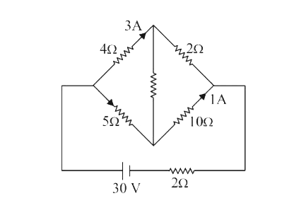
View SolutionIn the given circuit, currents through 4Ωand10Ω resistances are as shown. The current through the 5Ω resistance is _________ A.
 View Solution
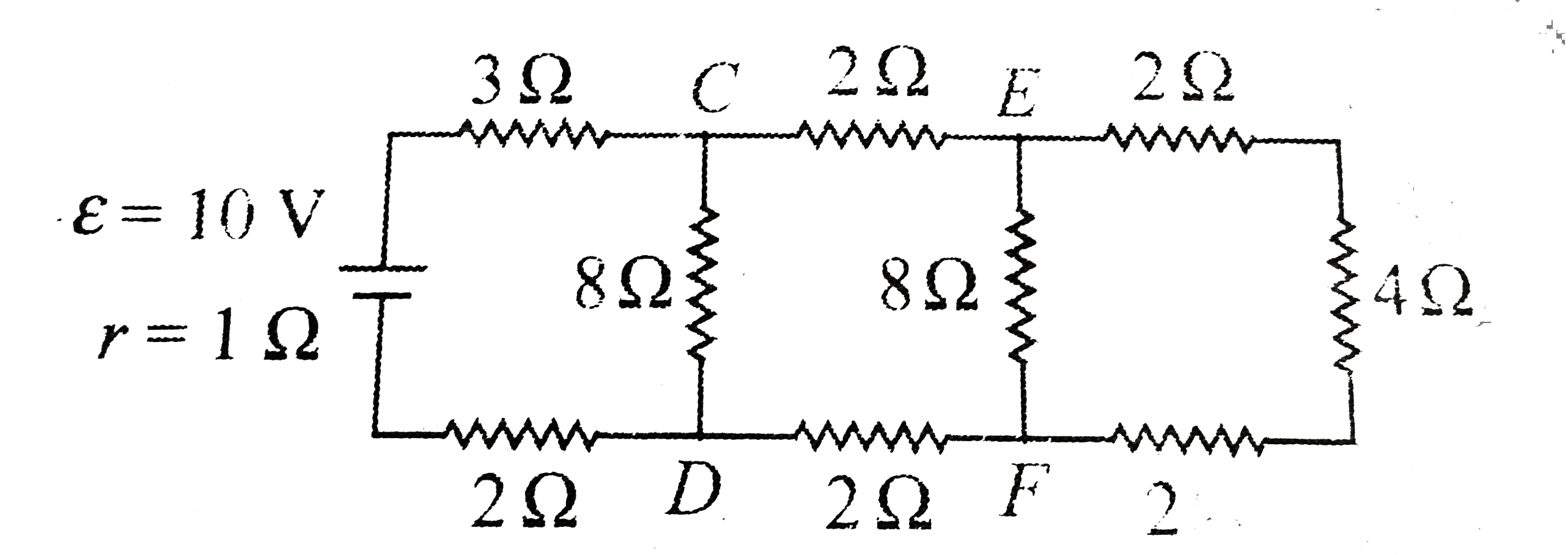
In the circuit shown in fig. the cell has emf 10V and internal resistance 1Ω
 View Solution
An alternating emf 200 volts at 50Hz is connected to a circuit resistance 1ohm and inductance 0.01H. What is the phase difference between the current and the emf in the circuit? Also, find the current in the circuit.
View Solution

