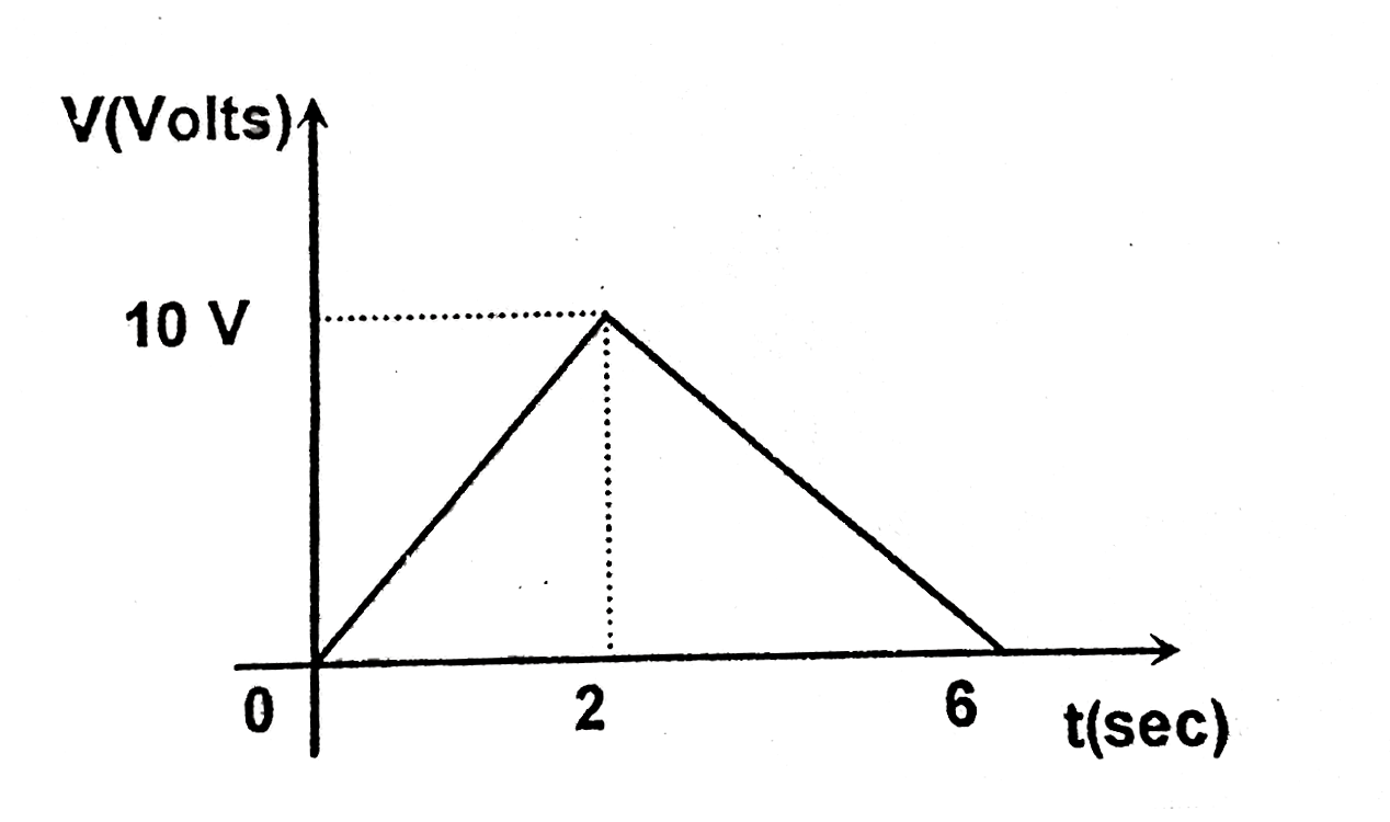
A circuit element is placed in a closed box. At time t=0, constant current generator supplying a current of 1 amp, is connected across the box. Potential difference across the box varies according to graph shown in figure. The element in the box is:
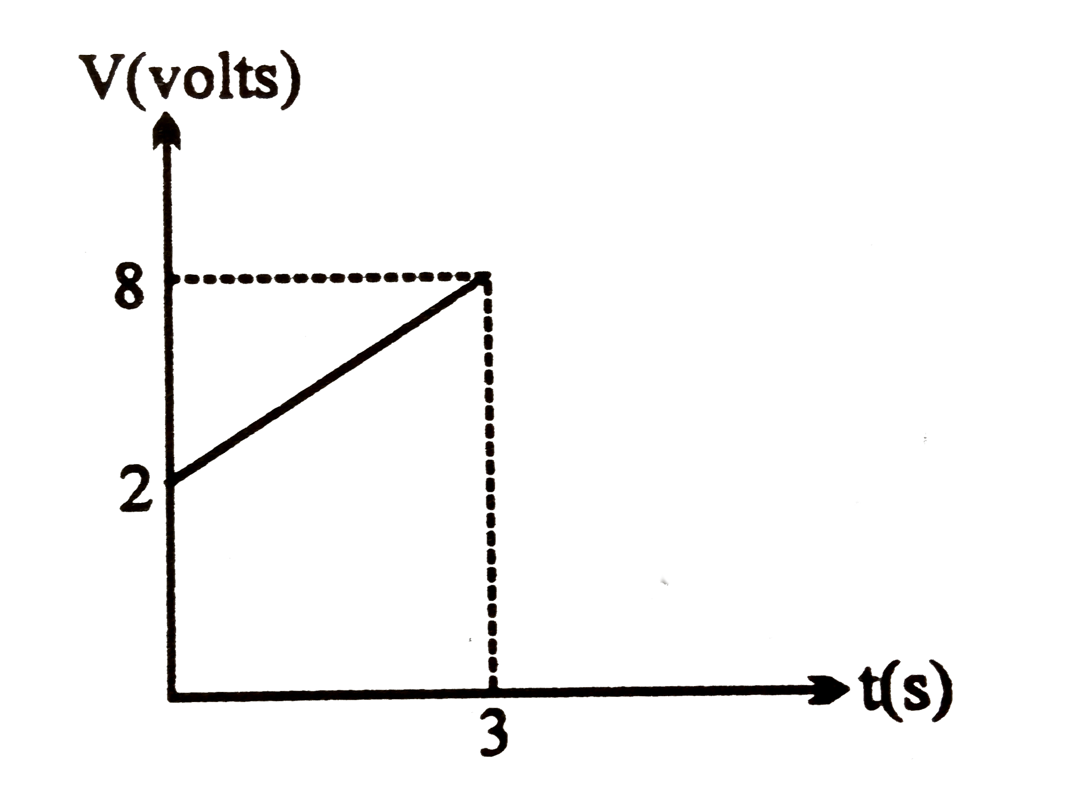
a resistance of 2Ω
a battery of emf 6 V
an inductance of 2 H
a capacitance of 0.5 F
The correct Answer is:D
For a capacitor, i=(dqdt)=C.(dVdt)
i.e., I = constant, if dVdt = constant
∴ Capacitance, C=i(dVdt)=12=0.5F
Topper's Solved these Questions
- ELECTROMAGNETIC INDUCTIONBOOK - DC PANDEY ENGLISHCHAPTER - ELECTROMAGNETIC INDUCTIONEXERCISE - Medical entrance special format questions
17 Videos
- ELECTROMAGNETIC INDUCTIONBOOK - DC PANDEY ENGLISHCHAPTER - ELECTROMAGNETIC INDUCTIONEXERCISE - Match the columns
5 Videos
- ELECTROMAGNETIC INDUCTIONBOOK - DC PANDEY ENGLISHCHAPTER - ELECTROMAGNETIC INDUCTIONEXERCISE - Check point
60 Videos
- CURRENT ELECTRICITYBOOK - DC PANDEY ENGLISHCHAPTER - CURRENT ELECTRICITYEXERCISE - Medical entrances gallery
97 Videos
- ELECTROMAGNETIC WAVESBOOK - DC PANDEY ENGLISHCHAPTER - ELECTROMAGNETIC WAVESEXERCISE - Sec C
22 Videos
Similar Questions
Knowledge Check
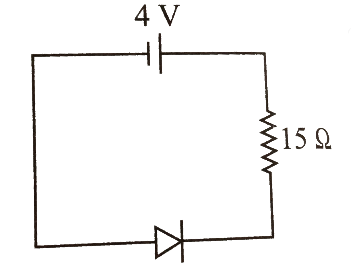
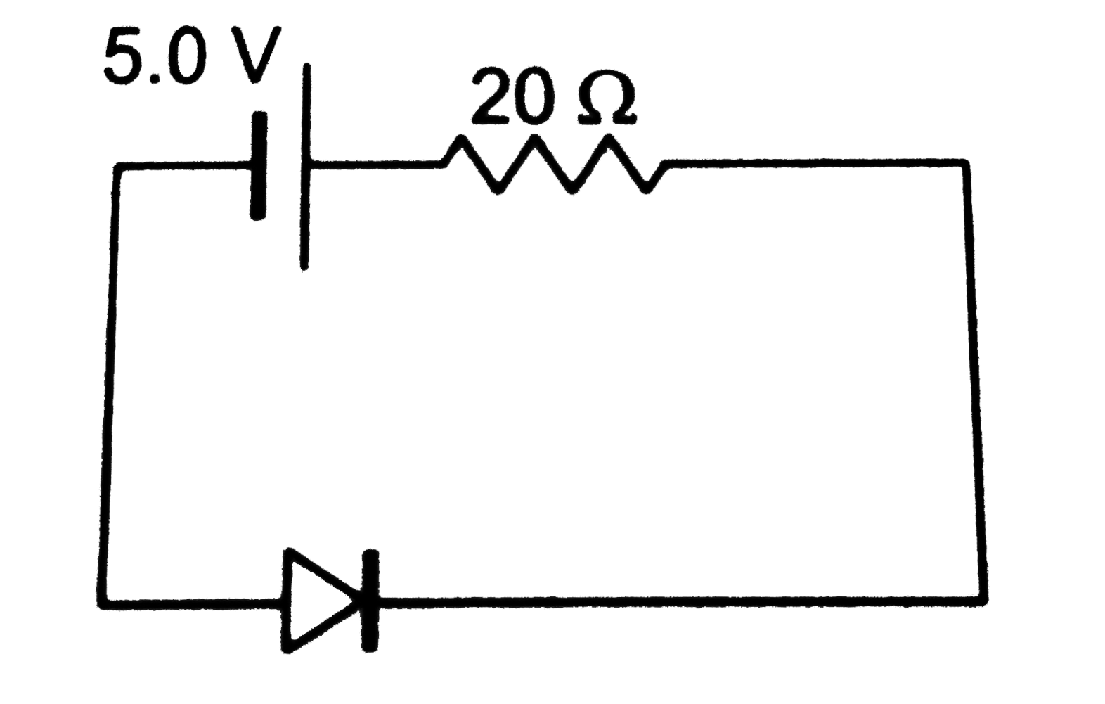
In the circuit shown if current for the diode is 20μA, the potential difference across the diode isA2 VB4.5VC4 VD2.5 V
The current i in an induction coil varies with time according to the graph shown in figure. Which of the following graph shows induced emf in the coil with time:
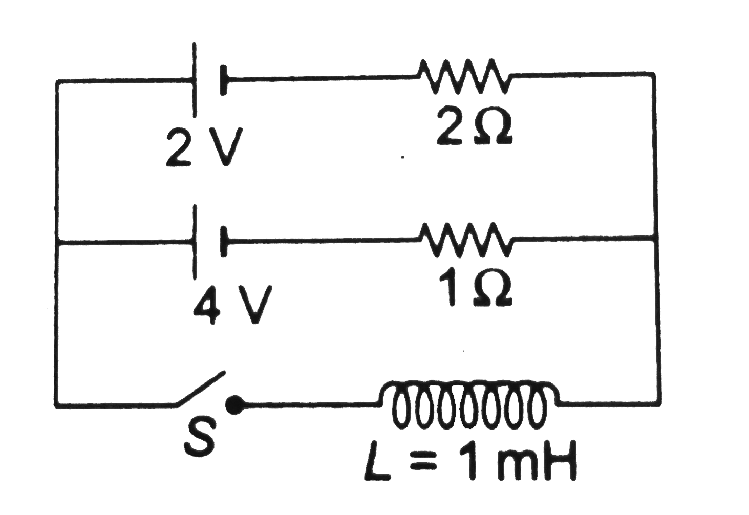
View SolutionIn the circuit shown, switch S is closed at time t=0. Find the current through the inductor as a function of time t.
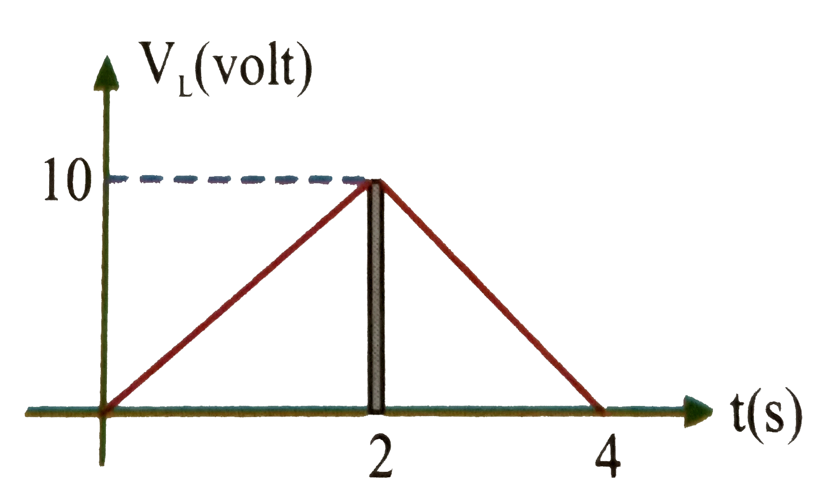
View SolutionThe potential difference across a 2H inductor as a function of time is shown in figure. At time t=0, current is zero
Current t=2 second is
View SolutionIn the circuit shown in figure switch S is closed at time t=0
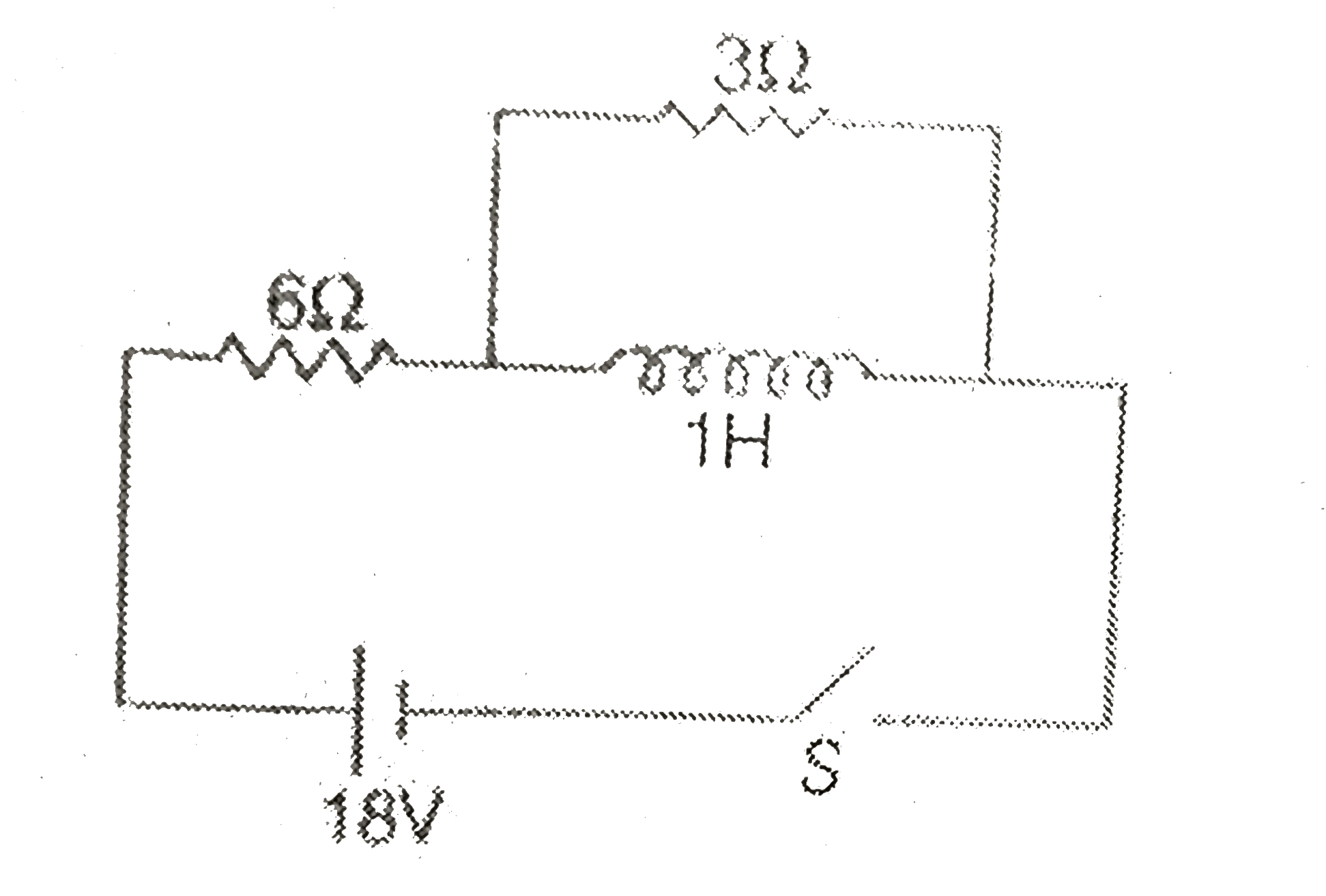
Potential difference across 3Ω resistance at time t is given by
View SolutionCalculate the current through the resistance connected across MN and the current supplied by each of the batteries in the circuit diagram shown in

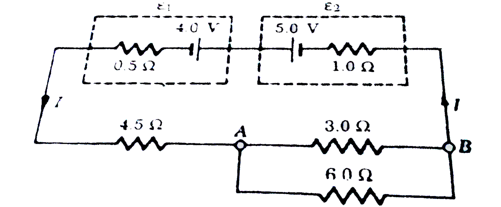
View SolutionIn the circuit shown in Fig. 4.41, calculate the current in each resistor and potential difference across each resistor.
View SolutionA constant voltage of 25 V is applied to a series L-R circuit at t = 0, by closing a switch. What is the potential difference across the resistor and the inductor at time t = 0?
View Solution

