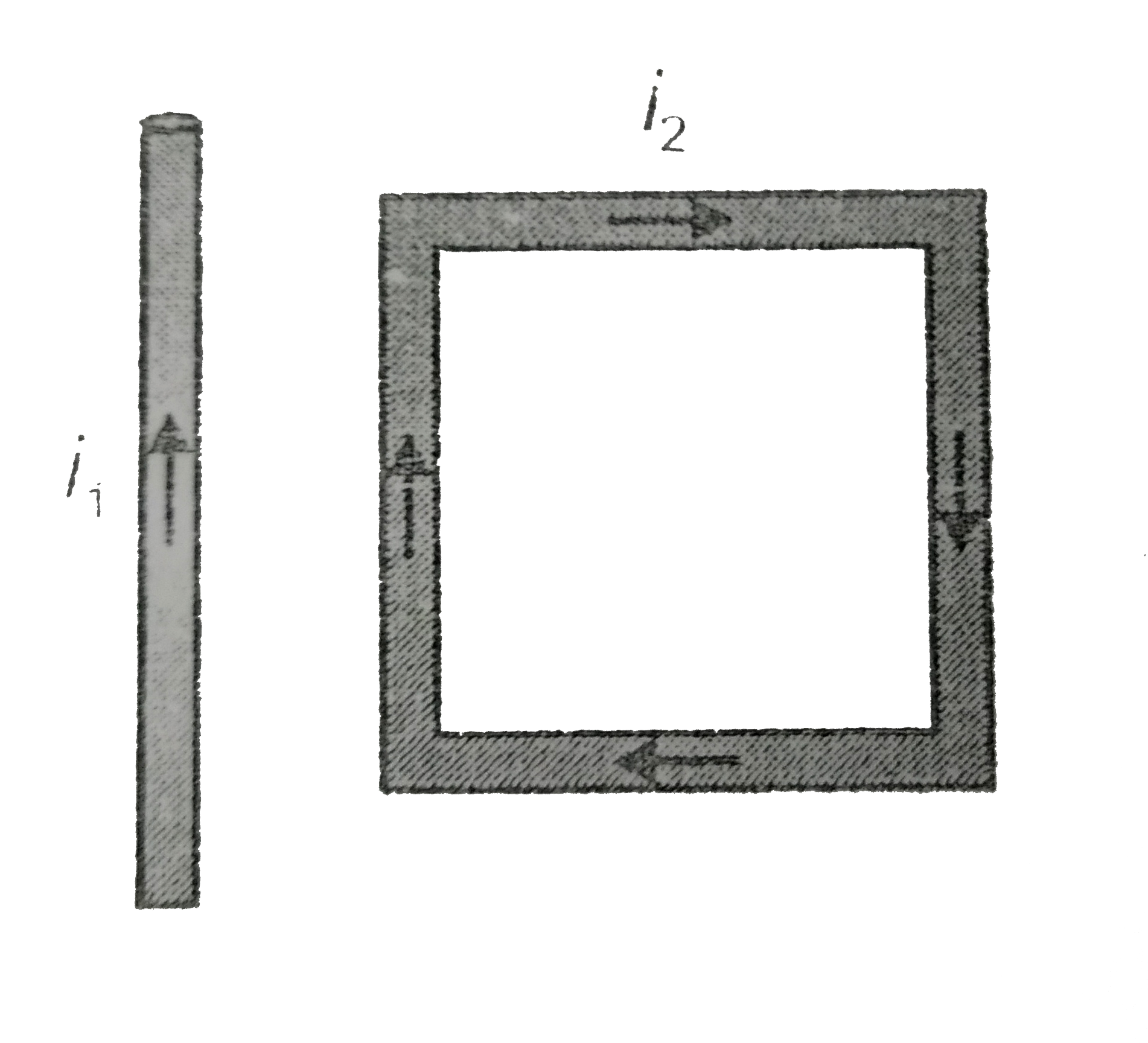
A thin rod, carrying current i2 is placed near a long straight wire carrying current i1 in the plane of rod as shown in figure. The motion of rod is
Translatory
Rotatory
Translatory as well as rotatory
Will not experience any force
To analyze the motion of the thin rod carrying current i2 placed near a long straight wire carrying current i1, we can follow these steps:
Step 1: Understanding the Magnetic Field
The long straight wire carrying current i1 generates a magnetic field around it. The magnetic field B at a distance d from the wire can be expressed using Ampere's Law:
B=μ0i12πd
where μ0 is the permeability of free space.
Step 2: Calculating the Force on the Rod
The thin rod carrying current i2 experiences a magnetic force due to the magnetic field created by the wire. The force F on the rod can be calculated using the formula:
F=i2LB
where L is the length of the rod and B is the magnetic field at the location of the rod. Substituting the expression for B:
F=i2L(μ0i12πd)
Thus, the force acting on the rod becomes:
F=μ0i2i1L2πd
Step 3: Analyzing the Nature of the Force
From the equation F=μ0i2i1L2πd, we can see that the force F is inversely proportional to the distance d. This means that as the distance d decreases, the force F increases.
Step 4: Determining the Motion of the Rod
The rod will experience a force that can cause both translational and rotational motion. The translational motion occurs due to the net force acting on the rod, while the rotational motion can occur if there is a torque about the center of mass of the rod, depending on the configuration of the system.
Conclusion
Since the force is inversely proportional to the distance d, the rod will experience both translatory and rotatory motion. Therefore, the correct answer to the question regarding the motion of the rod is:
Answer: The motion of the rod is both translatory and rotatory.
The long straight wire carrying current i1 generates a magnetic field around it. The magnetic field B at a distance d from the wire can be expressed using Ampere's Law:
B=μ0i12πd
where μ0 is the permeability of free space.
The thin rod carrying current i2 experiences a magnetic force due to the magnetic field created by the wire. The force F on the rod can be calculated using the formula:
F=i2LB
where L is the length of the rod and B is the magnetic field at the location of the rod. Substituting the expression for B:
F=i2L(μ0i12πd)
Thus, the force acting on the rod becomes:
F=μ0i2i1L2πd
From the equation F=μ0i2i1L2πd, we can see that the force F is inversely proportional to the distance d. This means that as the distance d decreases, the force F increases.
The rod will experience a force that can cause both translational and rotational motion. The translational motion occurs due to the net force acting on the rod, while the rotational motion can occur if there is a torque about the center of mass of the rod, depending on the configuration of the system.
Since the force is inversely proportional to the distance d, the rod will experience both translatory and rotatory motion. Therefore, the correct answer to the question regarding the motion of the rod is:
Topper's Solved these Questions
Similar Questions
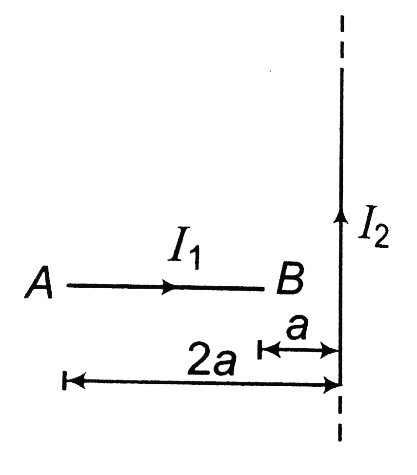
A segment AB of wire carrying current I1 is placed perpendicular to a long straight wire carrying current I2 as shown in figure. The magnitude of force experieced by the straight wire AB is
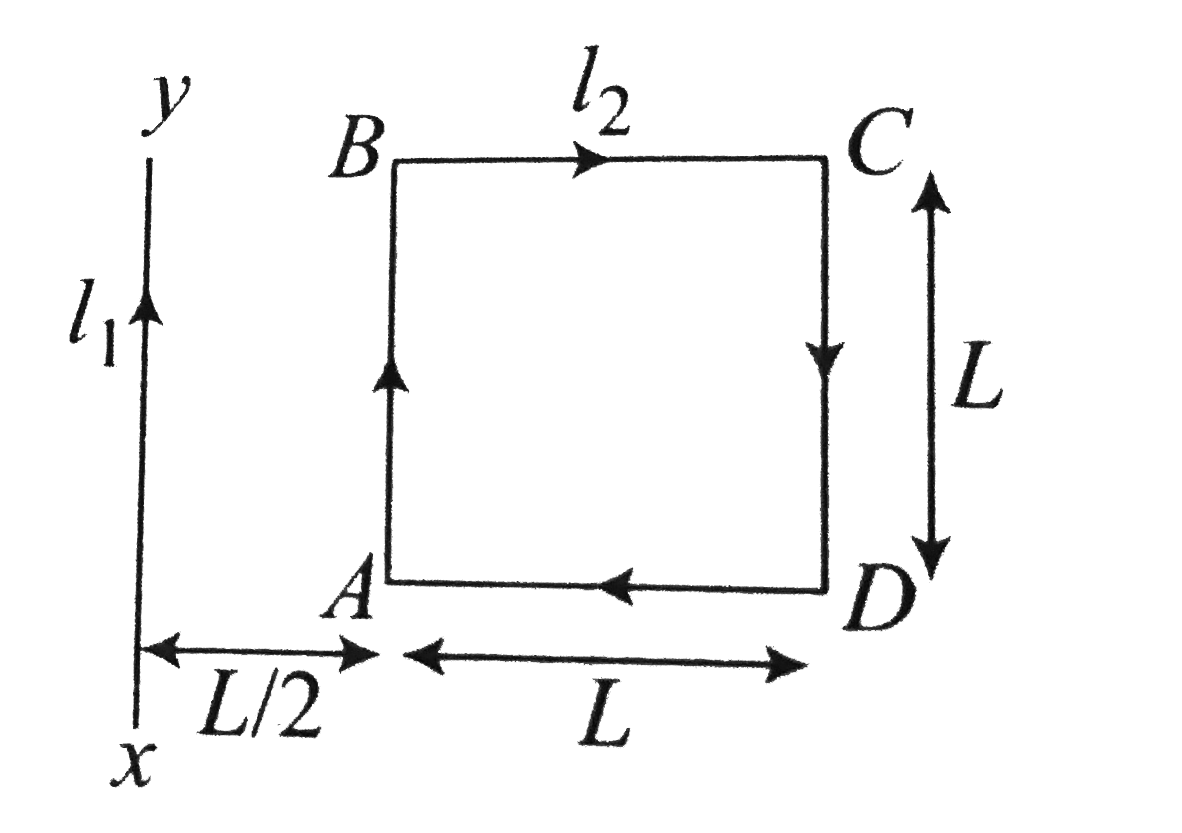
View SolutionA square loop ABCD, carrying a current I2 is placed near and coplanar with a long straight conductor XY, carrying a current I1 as shwon in Figure. The net force on the loop will be
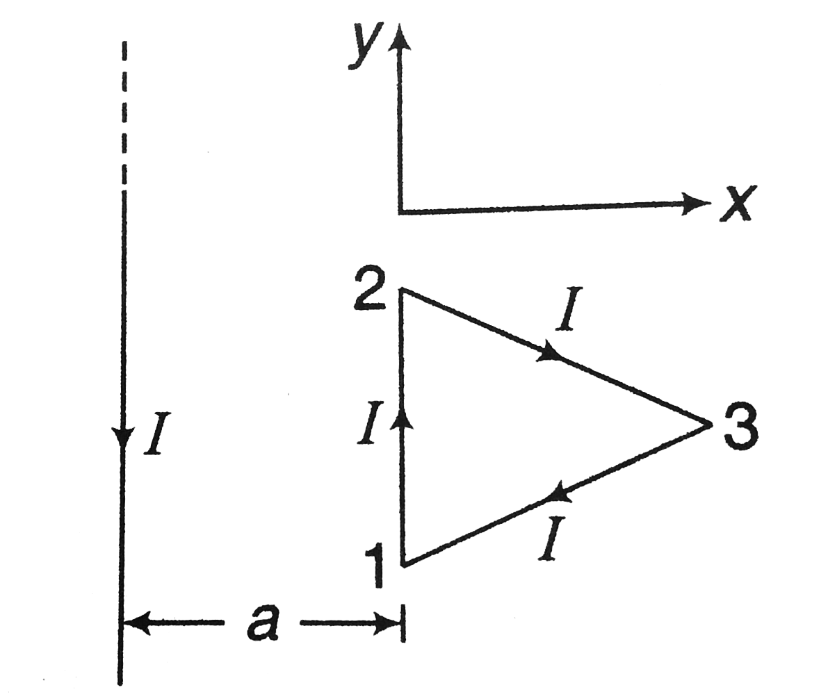
View SolutionAn equilateral triangular frame with side a carrying a current I is placed at a distance a from an infinitely long straight wire carrying a current I as shown in the figure. One side of the frame isparallel to the wire. The whole system lies in the xy-plane. Find the magnetic force F acting on the frame.
View SolutionA rectangular loop carrying a current i2 situated near a long straight wire carrying a steady current i1. The wire is parallel to one of the sides of the loop and is in the plane of the loop as shown in the figure. Then the current loop will
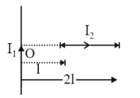
View SolutionA finite carrying - current wire is placed in a plane along with very long ,straight conductor carrying current as shown in the figure. The torque on the finite current wire about point O is
View SolutionA straight conductor of length l carrying a current l is placed perpendicular to a long straight conductor which carries a current io as shown in the figure. Find the force of interaction between them.

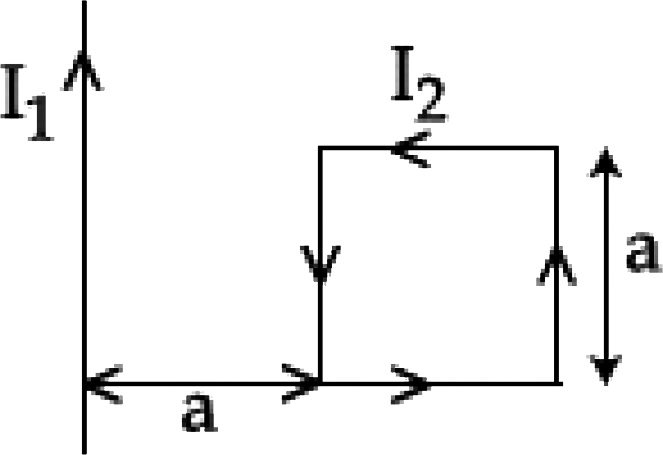
View SolutionA rigid square loop of side 'a' and carrying current I2 is lying on a horizontal surface near a long current I1 carrying wire in the same plane as shown in figure. The net force on the loop to the wire will be :
View SolutionA conductor AB of length L carrying a current I', is placed perpendicular to a long straight conductor XY carrying a current I as shown in Fig. The forces on AB has magnitude
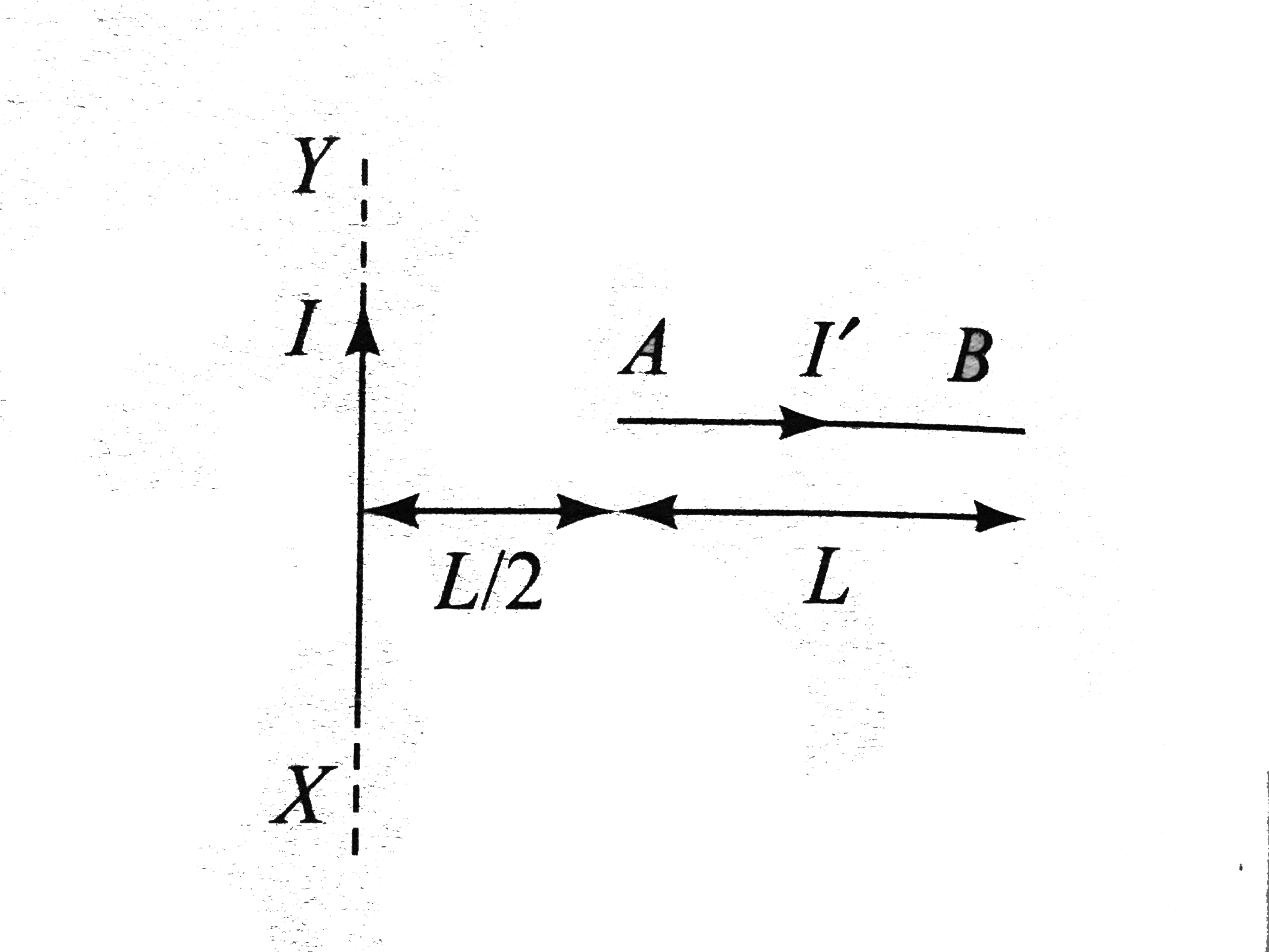
View SolutionA conductor AB of length L carrying a current I', is placed perpendicular to a long straight conductor XY carrying a current I as shown in Fig. The forces on AB has magnitude

View SolutionAnswer the following:
(a) Define mutual inductance and write its S.I. unit.
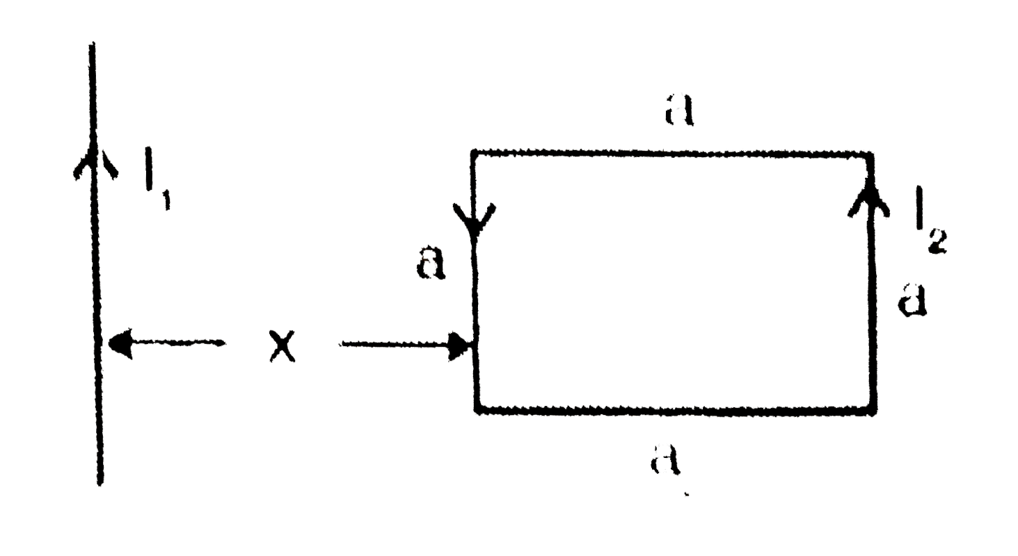
(b) A square loop of side a carrying a current I2 is kept at distance x from an infinitely long straight wire carrying a current I1 as shown in the figure. Obtain the expression for the resultant force on the loop.
View Solution