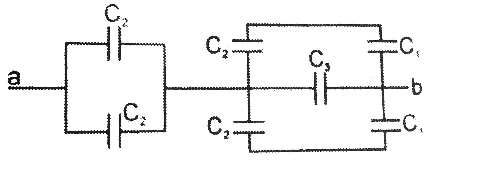
A combination arrangement of the capacitors is shown in the figure
(i) C1=3μF,C2=6μF and C3=2μF then equivalent capacitance between 'a' and 'b' is :
8μC
16μC
32μC
64μC
The correct Answer is:D
Step by step video & image solution for A combination arrangement of the capacitors is shown in the figure (i) C_(1)=3 mu F, C_(2) =6 mu F and C_(3)= 2 mu F then equivalent capacitance between 'a' and 'b' is : by Physics experts to help you in doubts & scoring excellent marks in Class 12 exams.
Updated on:21/07/2023Topper's Solved these Questions
- CAPACITANCEBOOK - RESONANCE ENGLISHCHAPTER - CAPACITANCEEXERCISE - Exercise - 3
26 Videos
- CAPACITANCEBOOK - RESONANCE ENGLISHCHAPTER - CAPACITANCEEXERCISE - High Level Problems
16 Videos
- CAPACITANCEBOOK - RESONANCE ENGLISHCHAPTER - CAPACITANCEEXERCISE - Exercise - 1
79 Videos
- ATOMIC PHYSICSBOOK - RESONANCE ENGLISHCHAPTER - ATOMIC PHYSICSEXERCISE - Advanved level problems
17 Videos
- COMMUNICATION SYSTEMSBOOK - RESONANCE ENGLISHCHAPTER - COMMUNICATION SYSTEMSEXERCISE - Exercise 3
13 Videos
Similar Questions
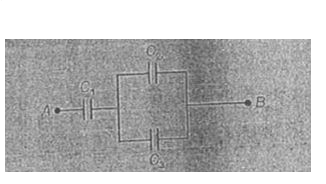
In the arrangement C1=10μ,FC2=10μF and C3=20μF . What is the equivalent capacitance ( in μF ) between points A and B ?
View Solution
(i) Find the equivalent capacitance of the combination shown in the figure (a), when C1=2.0μF,C2=4.0μFandC3=3.0μF
(ii) The input terminals A and B in Fig. (a) are connected to a battery of 12 V. Find the potential and the charge of each capacitor.
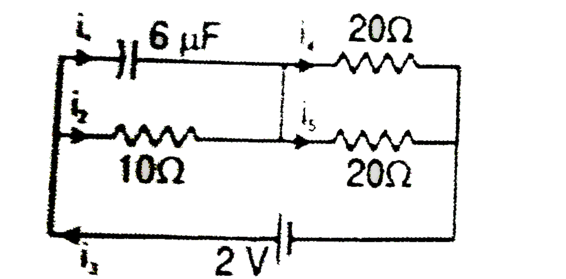
View SolutionIn steady state, find the charge on the capacitor in (μC) shown in figure.
View SolutionIn the arrangement of the capacitor shown in the figure, each C1 capacitor has capacitance of 3μF and each C2 capacitor has capacitance of 2μF then,
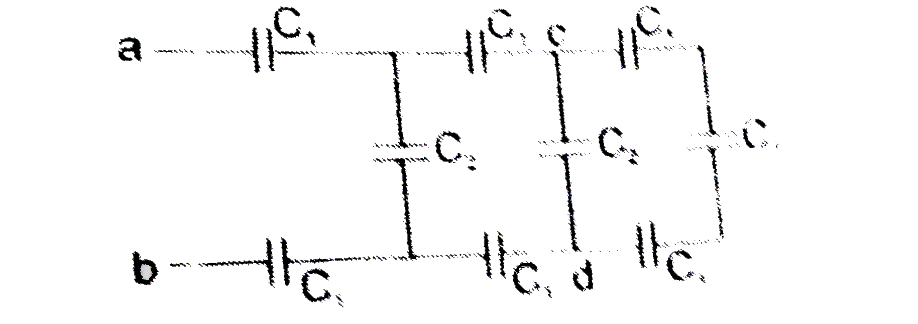
(i) Equivalent capacitance of the network between the points a and b is :
View SolutionIn the arrangement of the capacitor shown in the figure, each C1 capacitor has capacitance of 3μF and each C2 capacitor has capacitance of 2μF then,
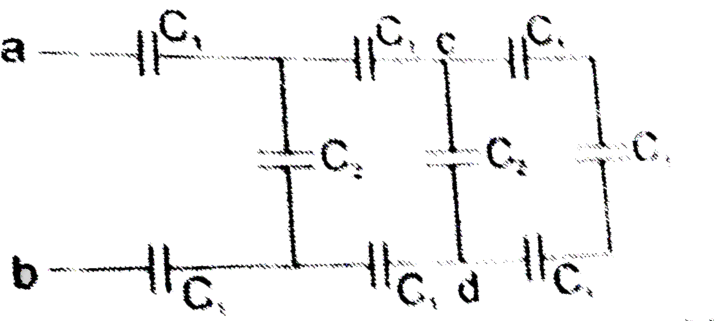
(ii) If Vab=900V, the charge on each capacitor nearest to the points 'a' and 'b' is :
View SolutionIn the arrangement of the capacitor shown in the figure, each C1 capacitor has capacitance of 3μF and each C2 capacitor has capacitance of 2μF then,
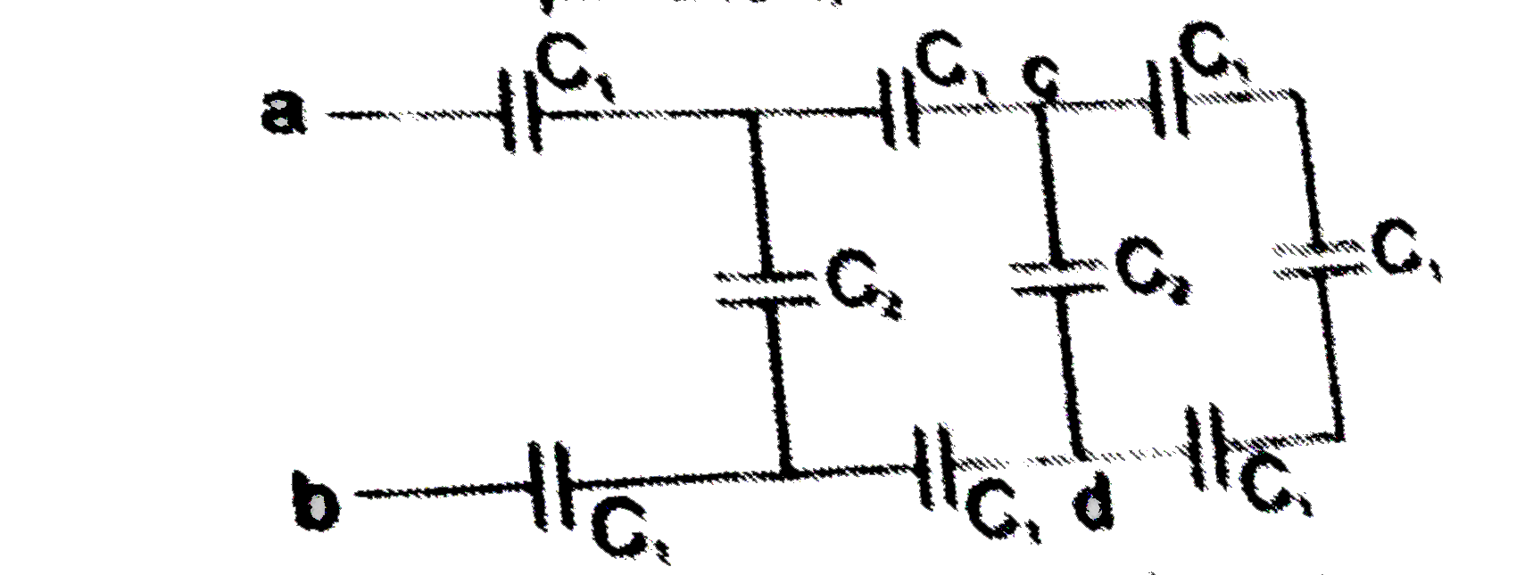
(iii) If Vab=900V, then potential difference across points c and d is :
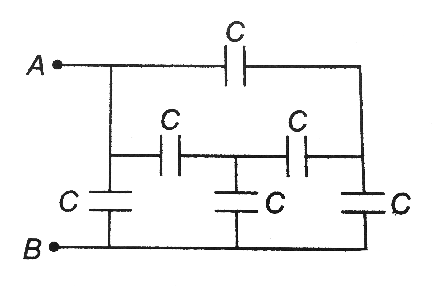
View SolutionSix capacitors C1=C2=C3=C4=C5=C6=C are arranged as shown in. Determine the equivalent capacitance between A and B.
View SolutionIn the circuit shown below C1=10μF, C2=C3=20μF, and C4=40μ F. if the charge on C1 is 20μC then potential difference between X and Y is
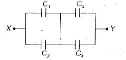
View Solution(i) Find out the charges on the three capacitors connected to a battery as shown in figure. Take C1=1.0μF,C2=2.0μF,C3=3.0μF and V=20 volt
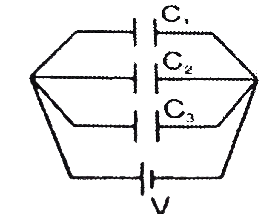
(ii) Find out the work done by the battery during the process of charging (initially all the capacitors are uncharged)
(iii) Find out the total energy stored in the capacitors.
View SolutionSix equal capacitors each of capacitance C are connected as shown in the figure. The equivalent capacitance between points A and B is
View Solution