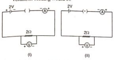
For the circuits shown in figure I and II the voltmeter reading would be
 Solution in Punjabi
2V In (I) and 0V in (II)
0V in both
2 v in both
0 V in (I) and 2 V in (II)
Step by step video & image solution for For the circuits shown in figure I and II the voltmeter reading would be by Physics experts to help you in doubts & scoring excellent marks in Class 10 exams.
Updated on:21/07/2023Topper's Solved these Questions
Similar Questions
Define electric current and give its unit
View SolutionWrite the S.I. unit of magnetic field →B.
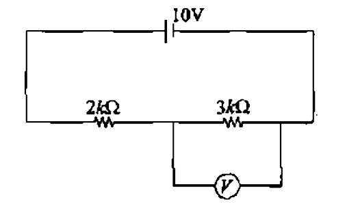
View SolutionIri the circuit shown in figure-3.334, the resistance of voltmeter is6kΩ. The voltmeter reading will be :
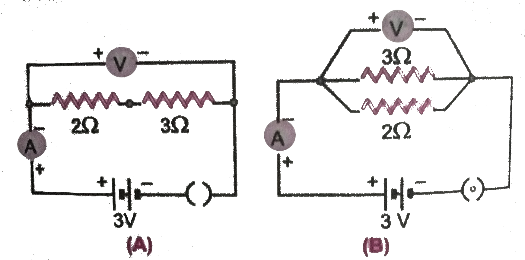
View SolutionFor the circuits AandB shown in (Fig. 3.64), what would be the voltmeter readings ?
 .
.
View SolutionIri the circuit shown in figure-3.334, the resistance of voltmeter is6kΩ. The voltmeter reading will be :

View SolutionIn the circuit shown in the figure, the voltmeter reading is
View SolutionIn the circuit shown in figure, what will be the reading of the voltmeter ?
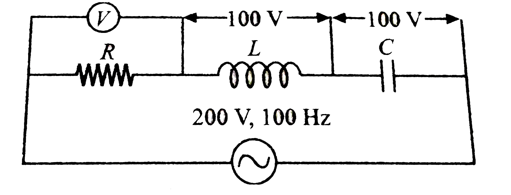
View SolutionA circuit is shown in the figure. The ratio of readings of ideal voltmeter to reading of ideal ammeter is
View SolutionIn the circuit shown in figure, what will be the readings of voltmeter and ammeter?
View SolutionIn the circuit shown in figure, what will be the reading of the voltmeter ?
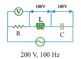
View SolutionIn the circuit shown in figure, what will be the reading of the voltmeter ?
View SolutionIs correct. In the circuit shown in the figure, the voltmeter reading would be.
View SolutionIn the circuit shown in figure, what will be the reading of the voltmeter ?

View SolutionWhat will be the reading of the voltmeter in the circuit shown in the figure?
View SolutionIn the circuit shown in figure-3.334, the resistance of voltmeter is6kΩ. The voltmeter reading will be :

View SolutionIn the circuit shown in the figure, the voltmeter reading is
View Solution
