Space is divided by the line AD into two regions. Region I is field free and the Region II has a unifrom magnetic field B direction into the plane of the paper. ACD is a simicircular conducting loop of radius r with center at O, hte plane of the loop being in the plane of the paper. The loop is now made to rotate with a constant angular velocity ω about an axis passing through O and the perpendicular to the plane of the paper. The effective resistance of the loop is R.
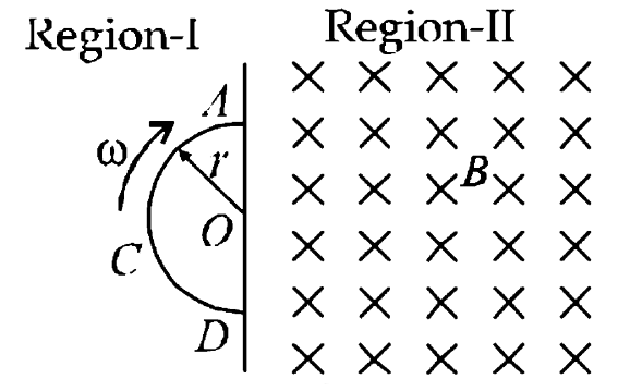
(i) obtain an expression for hte magnitude of the induced cureent in the loop.
(ii) Show the direction of the current when the loop is entering into the Rigion II.
Plot a graph between the induced e.m.f and the time of roation for two periods or rotation.
The correct Answer is:A, B, C
(i) Induced emf
E=−dϕdt=−ddt(B×A)
=−ddt[B(12r2θ)]=−12B(r2)dθdt=−12B(r2)(ω)
∴I=ER=−12b(r2)ωR⇒|I|=12B(r2)ωR
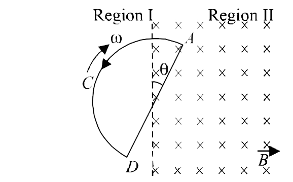
(ii)The loop is entering in the magnetic field and hance magnetic lines of force passing through the loop is increasing in the downward direction. Therefore, current will flow in the loop in such a direction which will oppose the change. The current will flow in the anticlockwise direction.
(iii) Graph between induced enf and period of rotation: For first half rotation, (t=T//2), when the loop enters the fields, the current is in anticlockwise direction.
Magnitude of current remains constant at
I=B(ω)(r2)/(2R)
Bω(r2)2R
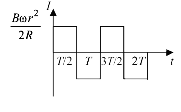
For next half rotation, when the loop comes out of the field, current of the same magnitude is set up clockwise.Anticlock current is supposed to be positive, The I-t graph is shown in the figure for two periods of rotation.
Topper's Solved these Questions
Similar Questions
A space is divided by the line AD into two regions. Region I is field free and the region II has a uniform magnetic field B directed into the paper. ACD is a semicircular conducting loop of radius r with centre at O, the plane of the loop being in the plane of the paper. The loop is now made to rotate with a constant angular velocity about an axis passing through O, and perpendicular to the plane of the paper in the clockwise direction. The effective resistance of the loop is R.
Obtain an expression for the magnitude of the induced current in the loop.
View SolutionA space is divided by the line AD into two regions. Region I is field free and the region II has a uniform magnetic field B directed into the paper. ACD is a semicircular conducting loop of radius r with centre at O, the plane of the loop being in the plane of the paper. The loop is now made to rotate with a constant angular velocity about an axis passing through O, and perpendicular to the plane of the paper in the clockwise direction. The effective resistance of the loop is R.
Show the direction of the current when the loop is entering into the region II.
View Solution
Knowledge Check
There is a uniform magnetic field directed perpendicular and into the plane of the paper. An irregular shaped conducting loop is slowly changing into a circular loop in the plane of the paper. Then
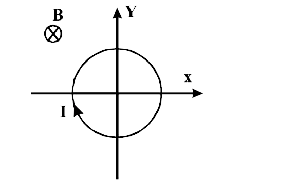
Acurrent is induced in the loop in the anticlockwise directionBcurrent is induced in the loop in the clockwise directionCAltrenating current is induced in the loopDno current is induced in the loopA conducting loop carrying a current I is placed in a uniform magnetic field ponting into the plane of the paper as shown. The loop will have a tendency to
 AcontractBexpandCmove towards +vex−aξsDmove towards −vex−aξs
The graph gives the magnitude B (t) of a uniform magnetic field that exists throughout a conducting loop, perpendicular to the plane of the loop. Rank the five regions of the graph according to the magnitude of the emf induced in the loop, greatest first
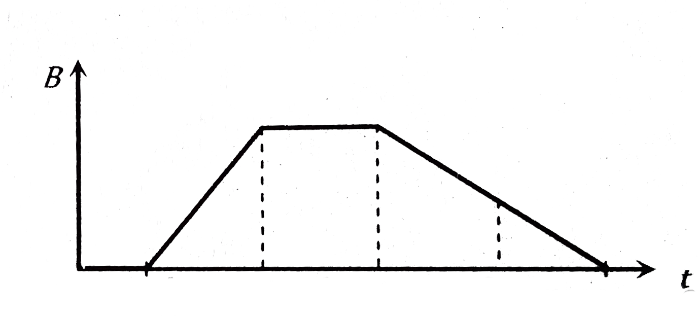 Ab>(d=e)<(a=c)Bb<(d=e)>(a=c)Cb<d<e<c<aDb>(a=c)>(d=e)
A space is divided by the line AD into two regions. Region I is field free and the region II has a uniform magnetic field B directed into the paper. ACD is a semicircular conducting loop of radius r with centre at O, the plane of the loop being in the plane of the paper. The loop is now made to rotate with a constant angular velocity about an axis passing through O, and perpendicular to the plane of the paper in the clockwise direction. The effective resistance of the loop is R.
Plot a graph between the induced emf and the time of rotation for two periods of rotation.
View SolutionA conducting circular loop of radius r is rotated about its diameter at a constant angular velocity ω in a magnetic field B perpendicular to the axis of rotation. In what position of the loop is the induced emf zero?
View SolutionA uniform magnetic field B=B0tˆi in a region exists. A circular conducting loop of radius r and resistance R is placed with its plane in yz-plane. Determine the current through the loop and sense of the current.
View SolutionThe graph gives the magnitude B(t) of a uniform magnetic field that exists throughout a conductig loop, perpendicular to the plane of the loop. Rank the five regions of the graph according to the magnitude fo the emf induced in the loop, greater first

View SolutionA conducting circular loop of radius r carries a constant current i. It is placed in a uniform magnetic field B such that B is perpendicular to the plane of the loop. The magnetic force acting on the loop is
View Solution
