Complete Solutions to Level 1 Objective of chapter CURRENT ELECTRICITY of Class 12 book with complete answers and questions
| Class 12 | PHYSICS |
| Chapter | CURRENT ELECTRICITY |
| DC PANDEY | Level 1 Objective |
| Number Of Questions | 40 |
| Academic Year | 2023-24 |
The net resistance of an ammeter should be small to ensure that
View SolutionA Steady current flows in a metalic conductor of non uniform cross section. The quantity/quantities which remain constant along the length of the conductor is/are
View SolutionIf M = mass, L = length, T = time and I = electric current, then the demensional formula of resistance R will be given by
View SolutionThe unit of electrical conductivity is
View SolutionThrough an electrolyte an electrical current is due to drift of
View SolutionThe current in a circuit with an external resistance of `3.75Omega is 2.5A`. When a resistance of `1 Omega` is introduced into the circuit, the current becomes `0.4 A`. The emf of the power source is
View SolutionThe deflection in a galnometer falls from 50 divisions to 20 divisions, when a `12Omega` shunt is applied. The galvanometer resistance is
View SolutionIf `2%` of the main current is to be passed through the galvanometer of resistance `G`, the resistance of shunt required is
View SolutionIf the length of the filament of a heater is reduced by `10%`, the power of the heater will
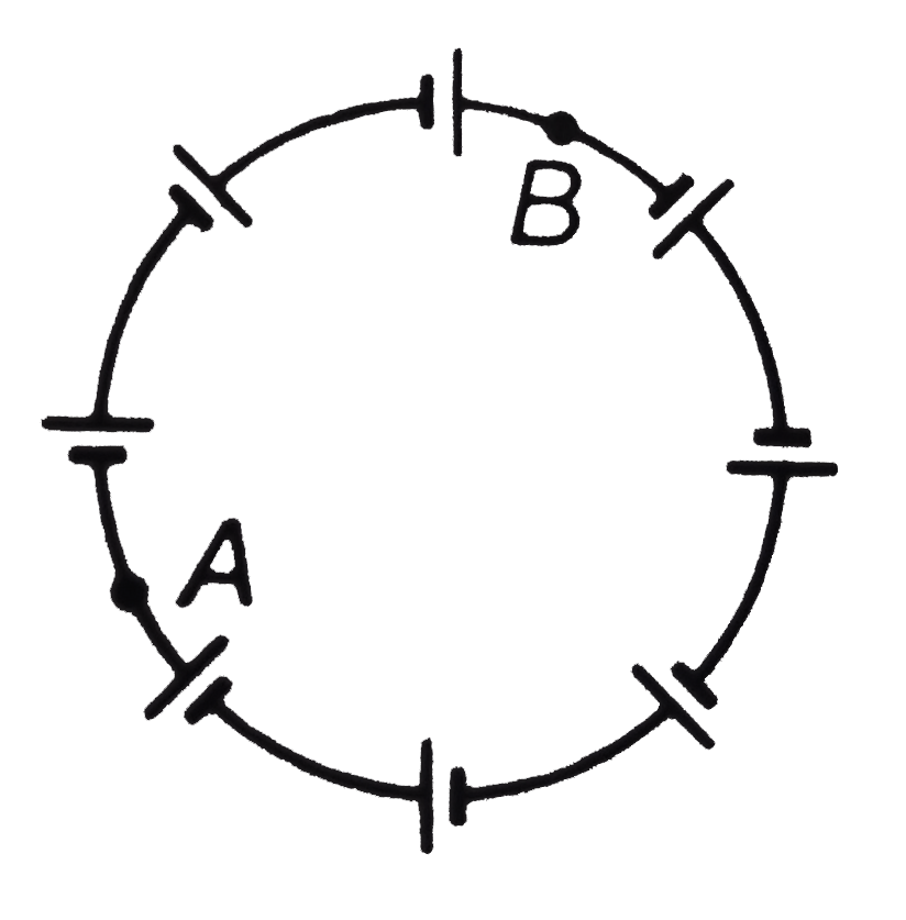
View SolutionN identical current sources each of emf E and internal resistance r are connected to form a closed loop as shown in figure. The potential difference between points A and B which divides the circuit into n and (N-n) units is
View SolutionA 2.0 V potentiometer is used to determine the internal resistance of `1.5 V` cell. The balance point of the cell in the circuit is `75 cm`. When a resistor of `10Omega` is connected across cel, the balance point sifts to `60 cm`. The internal resistance of the cell is
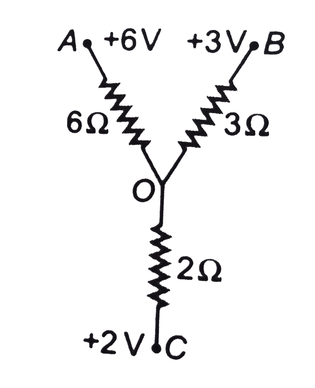
View SolutionThree resistance are joined together to form a letter Y, as shown in figure. If the potentials of the terminals `A, B` and `C` are `6V, 3V` and `2V` respectively, then the potential of the point O will be
View SolutionThe drift velocity of free elecrons in a conductor is `v`, when a current i is flowing in it. If both the radius and current are doubled, then the drift velocity wil be
View SolutionA galvanometer is to be converted into an ammeter or voltmeter. In which of the following cases the resistance of the device is largest?
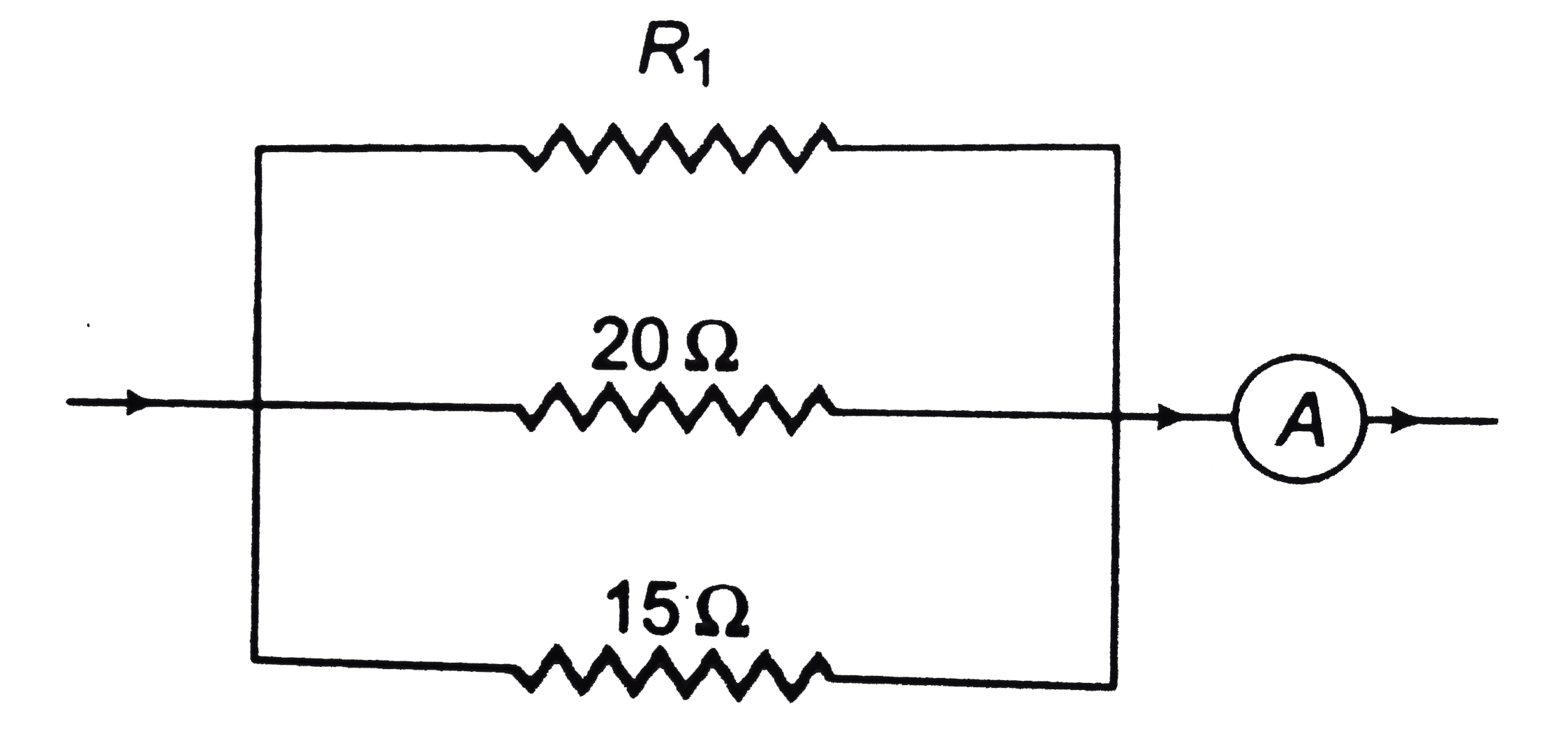
View SolutionIn the given circuit current flowing through the resistance `20Omega` is `0.3A,` while the ammeter reads 0.8 A. What is the value of `R_1`
View SolutionAn ammeter and a voltmeter are joined in series to a cell. Their readings are `A` and `V` respectively. If a resistance is now joining parallel with the voltmeter. Then
View SolutionA resistor `R` has power of dissipation `P` with cell voltage `E`. The resistor is cut in equal parts and all parts are connected in parallel with same cell. The new power dissipation is
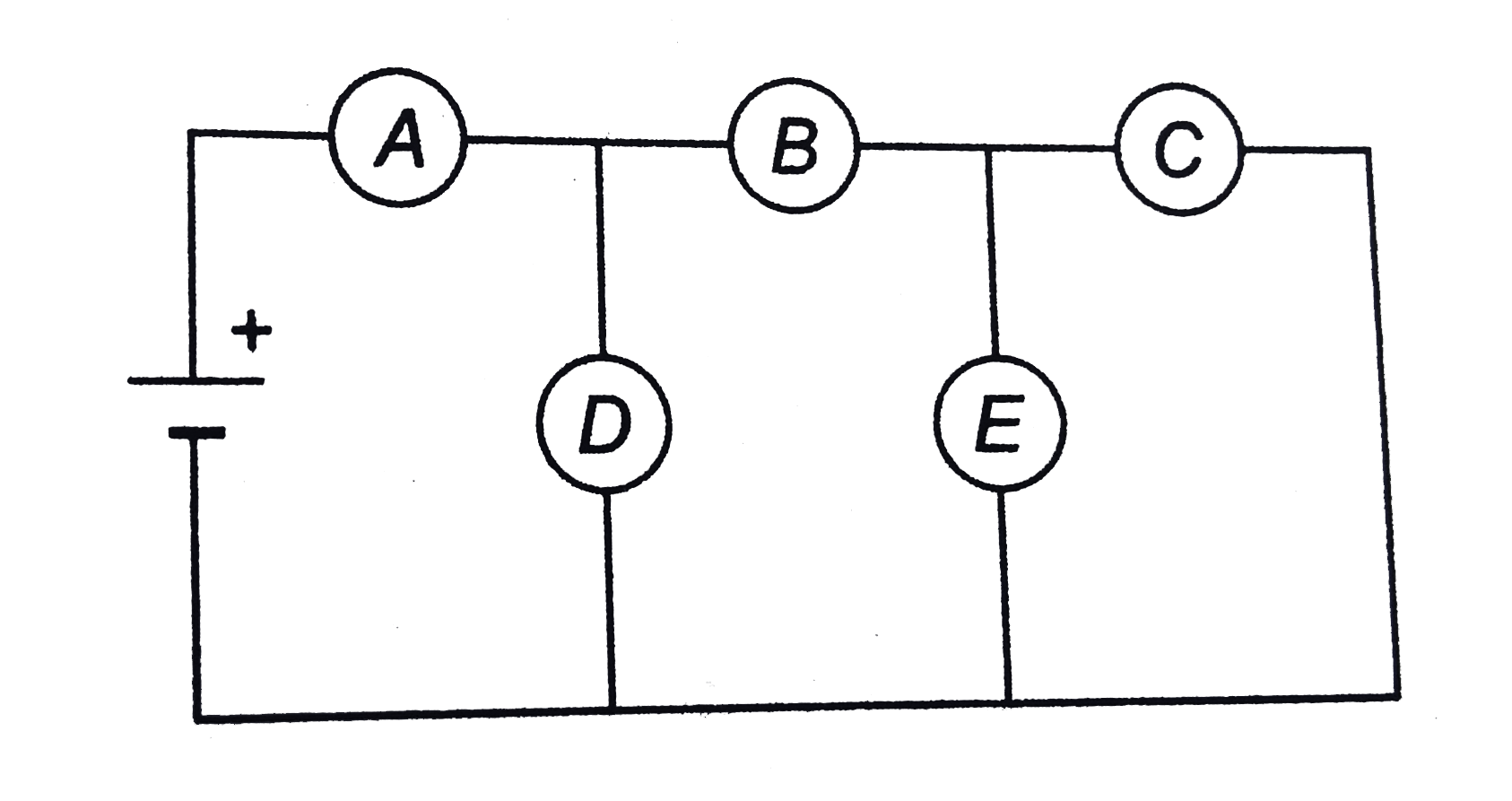
View SolutionIn the circuit diagram shown in figure,a fuse bulb can cause all other bulbs to go out. Identify the bulb
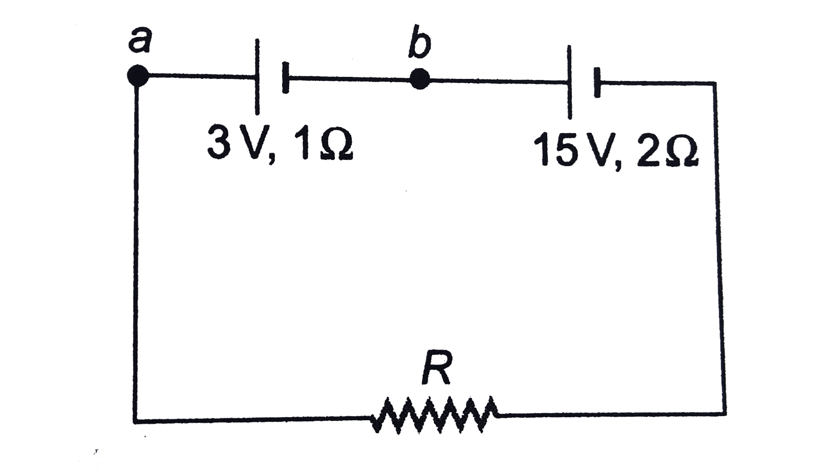
View SolutionTwo batteries one of the emf `3V`, internal resistance `1Omega` and the other of emf `15 V`, internal resistance `2Omega` are connected in series with a resistance `R` as shown. If the potential difference between points a and b is zero, the resistance `R` in `Omega` is
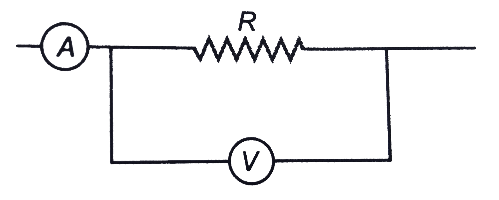
View SolutionA part of a circuit is shown in figure. Here reading of ammeter is `5A` and voltmeter is `100 V`. If voltmeter resistance is `2500 ohm`, then the resistance `R` is approximately
View SolutionA copper wire of resistance `R` is cut into ten parts of equal length. Two pieces each are joined in series and then five such combination are joined in parallel. The new combination will have resistance
View SolutionTwo resistances are connected in two gaps of a meter bridge. The balance point is `20 cm` from the zero end. A resistance of `15 Omega` is connected in series with the smaller of the two. The null point shifts to `40 cm`. The value of the smaller resistance in `Omega` is
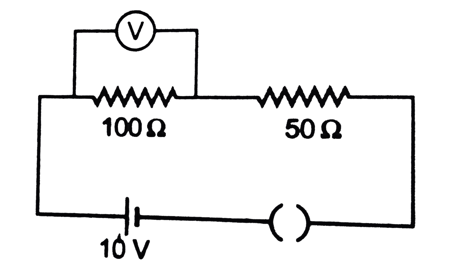
View SolutionIn the given circuit, the voltmeter records 5 volt. The resistance of the voltmeter in `Omega` is
View SolutionThe wire of potentiometer has resistance `4Omega` and length `1m`. It is connected to a cell of emf 2 volt and internal resistance `1Omega`. If a cell of emf 1.2 volt is balanced by it, the balancing length will be
View SolutionThe potential difference between points `A` and `B`, in a section of a circuit shown in

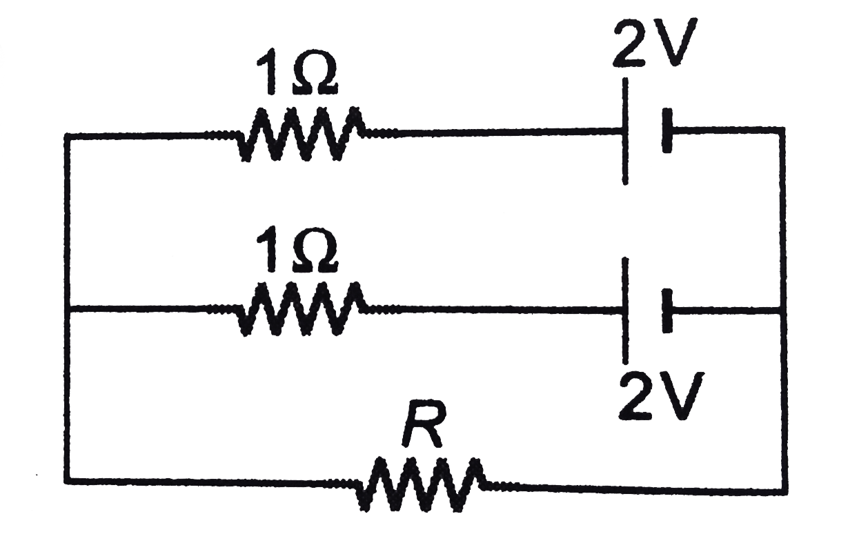
View SolutionTwo indentical batteries, each of emf `2V` andinternal resistance `r=1Omega` are connected as shown. The maximum power that can be developed across `R` using these batteries is
View SolutionFor a cell, the terminal potential difference is `2.2 V`, when circuit is open and reduces to `1.8 V `. When cell is connected to a resistance `R=5Omega`, the internal resistance of cell `(R)` is
View SolutionPotentiometer wire of length `1 m` is connected in series with `490 Omega` resistance and `2 V` battery. If `0.2 mV/cm` is the potential gradient, then resistance of the potentiameter wire is approximately
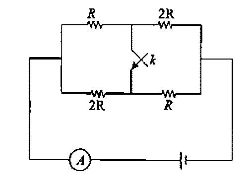
View SolutionFind the ratio ofcurrents as measured by ammeter in two cases when the key is open and when the key is closed :
View SolutionA galvanometer has a resistance of `3663Omega`. A shunt `S` is connected across it such that (`1//34`) of the total current passes through the galvanometer. Then the value of the shunt is
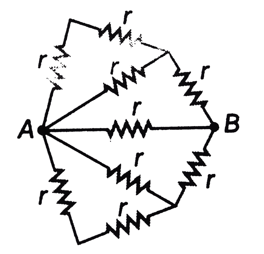
View SolutionThe network shown in figure is an arrangement of nine identical resistors. The resistance of the network between points `A` and `B` is `1.5 Omega`. The resistance r is
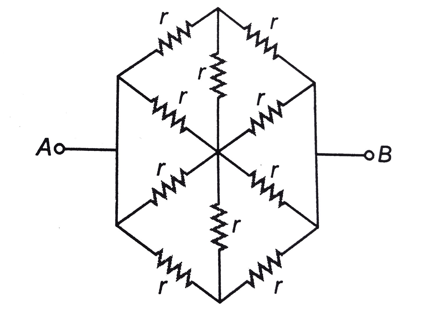
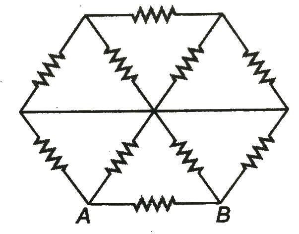
View SolutionThe equivalent resistance of the hexagonal network as shown figure between points `A` and `B` is
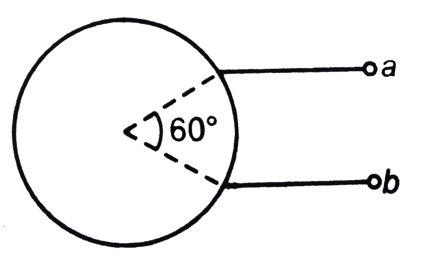
View SolutionA uniform wire of resistance `18 Omega` is bent in the form of a circle. The effective resistance across the points a and b is
View SolutionEach resistor shown in figure is an infinite network of resistance`1Omega`. The effective resistance Between points A and B is

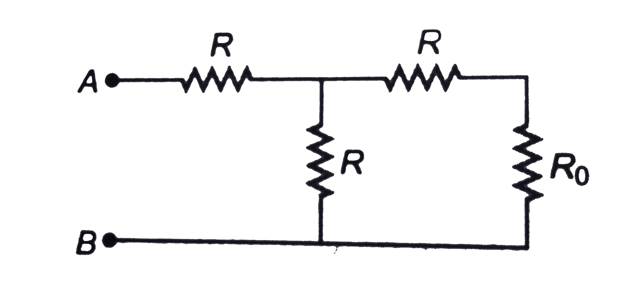
View SolutionIn the circuit shown in figure the total resistance between points `A` and `B` is `R_0`. The value of resistance `R` is
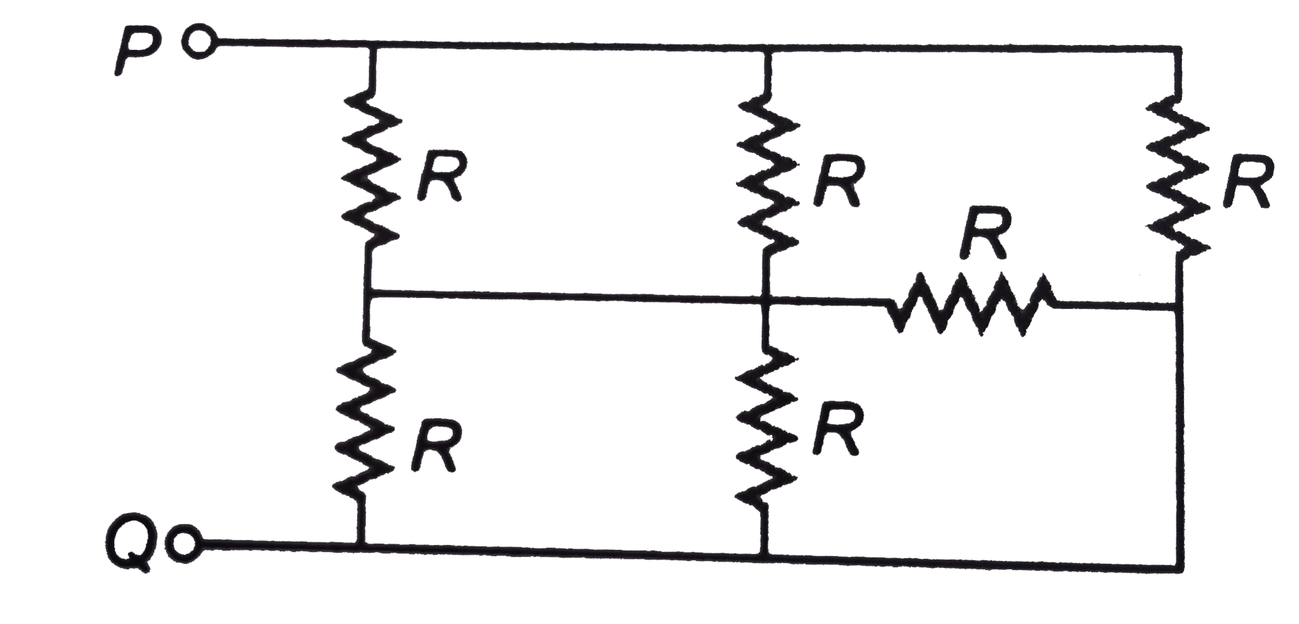
View SolutionIn the circuit shown in figure `R=55 Omega` the equivalent resistance between the point `P` and `Q` is
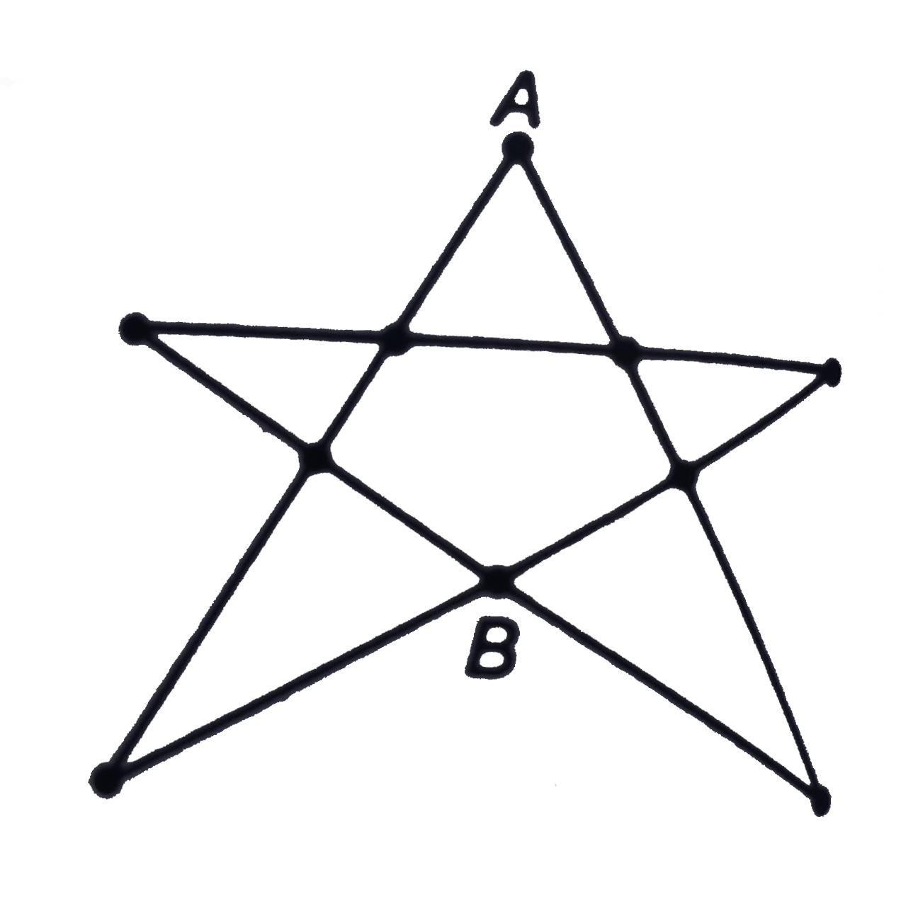
View SolutionThe resistance of all the wires between any two adjacent dots is `R`. Then, equivalent resistance between `A `and `B` as shown in figure is
View SolutionA uniform wire of resistance `4Omega` is bent into circle of radius `r`. As specimen of the same wire is connected along the dimeter of the circle. What is the equivalent resistance across the ends of this wire?
View SolutionIn the network shown in figure, each resistance is R. The equvalent resistance between points A and B is
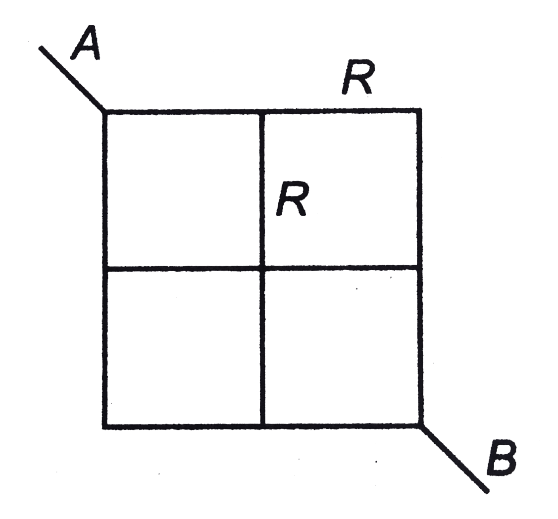
View SolutionThe equivalent resistance between the points `A` and `B` is (`R` is the resistance of each side of smaller square)
View Solution
Level 1 Objective questions and complete solutions for chapter CURRENT ELECTRICITY of DC PANDEY ENGLISH of Class 12
All Exercises from DC PANDEY Class 12 PHYSICS CURRENT ELECTRICITY
- B. Assertion and reason
- Check point
- Example
- Example Example Type
- Example Type 1
- Example Type 2
- Example Type 3
- Example Type 4
- Example Type 5
- Example Type 6
- Exercise 23.1
- Exercise 23.10
- Exercise 23.11
- Exercise 23.12
- Exercise 23.13
- Exercise 23.2
- Exercise 23.3
- Exercise 23.4
- Exercise 23.5
- Exercise 23.6
- Exercise 23.7
- Exercise 23.8
- Exercise 23.9
- Level 1 Assertion And Reason
- Level 1 Objective
- Level 1 Subjective
- Level 2 Comprehension Example Type
- Level 2 More Than One Correct
- Level 2 Single Correct
- Level 2 Subjective
- Match the columns
- Medical entrances gallery
- Miscellaneous Examples
- OBJECTIVE_TYPE
- Taking it together