Complete Solutions to Level 1 Subjective of chapter CURRENT ELECTRICITY of Class 12 book with complete answers and questions
| Class 12 | PHYSICS |
| Chapter | CURRENT ELECTRICITY |
| DC PANDEY | Level 1 Subjective |
| Number Of Questions | 53 |
| Academic Year | 2023-24 |
When a steady current passes through a cylindrical conductor, is there an electric field inside the conductor?
View SolutionDetermine True or False. Electrons in a conductor have no motion in the absence of a potential difference across it.
View SolutionIn the Bohr model of hydrogen atom, the electron is pictured to rotate in a circular orbit of radius `5xx 10^-11 m`, at a speed `2.2 xx 10^6` m/ s. What is the current associated with electron motion?
View SolutionA `120 V` house circuit has the following light bulbs switched on : `40 W, 60 W` and `75 W`. Find the equivalent resistance of these bulbs.
View SolutionAssume that the batteries in figure have negligible internal resistance. Find
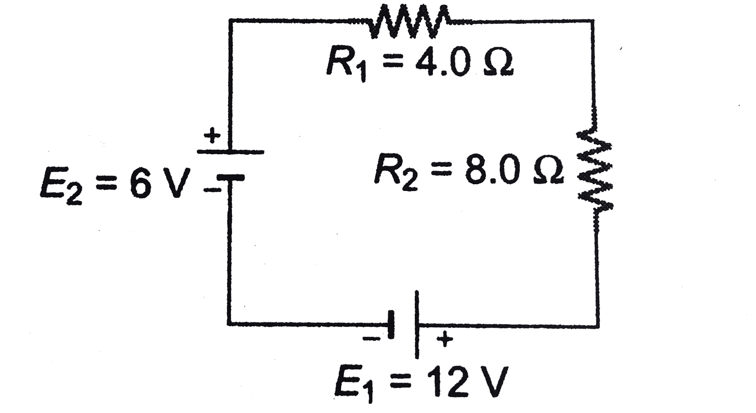
a. the current in the circuit,
(b) the power dissipated in each resistor and
(c) the power of each battery, stating whether energy is supplied by or absorbed by it
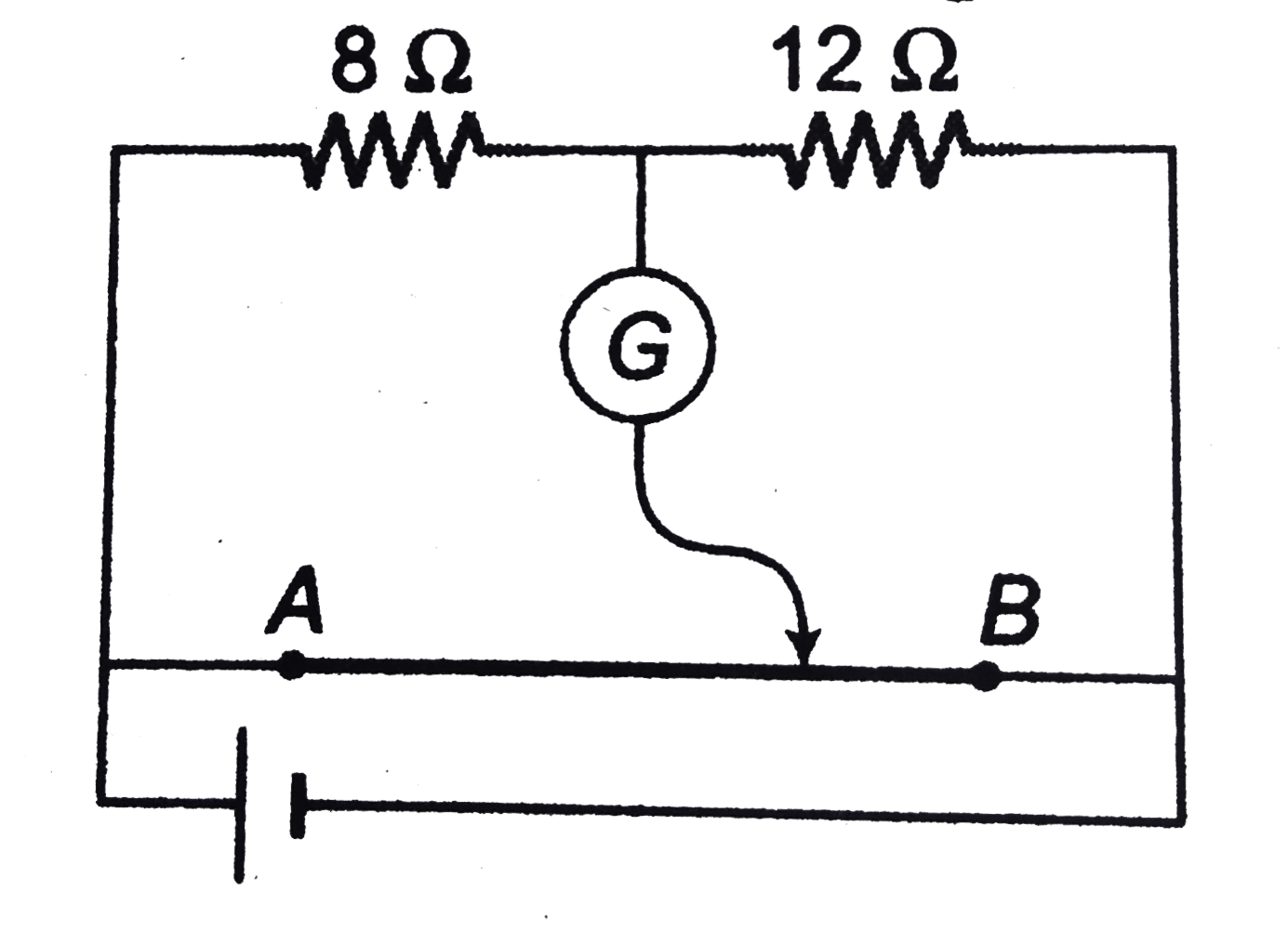
View SolutionThe potentiometer wire `AB` shown in figure is `40 cm` long. Where the free end of the galvanometer should be connected on `AB` so that the galvanometer may show zero deflection?
View SolutionAn ideal voltmeter `V` is connected to a `2.0 Omega` resistor and a battery with emf `5.0 V` and internal resistance `0.5 Omega` as shown in figure
(a) What is the current in the `2.0 Omega` resistor?
(b) What is the terminal voltage of the battery?
(c) What is the reading of the voltmeter?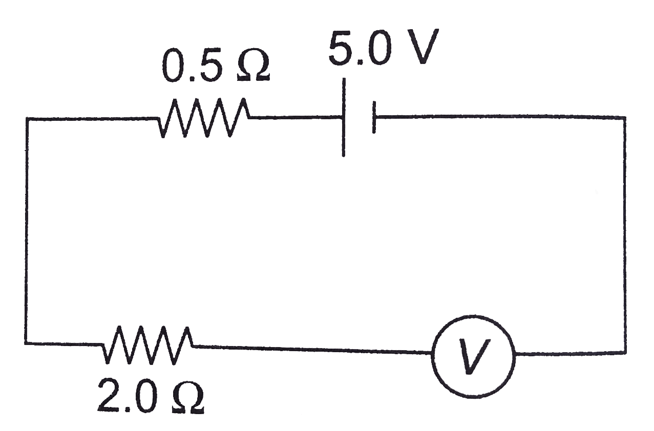
View Solution
In Figure `E_1=12V` and `E_2=8V`
(a) What is the direction of the current in the resistor?
(b) Which battery is doing positive work?
(c) Which point, `A` or `B`, is at the higher potential?
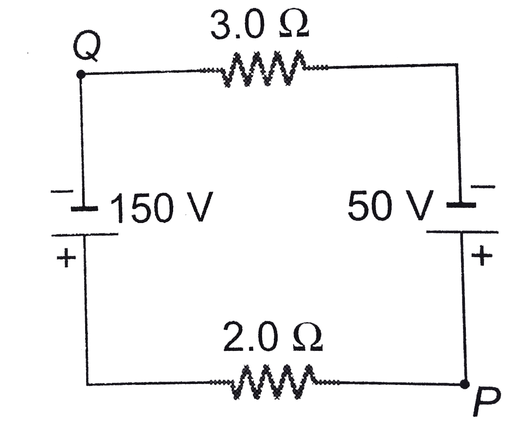
View SolutionIn Figure if the potential at Point P is `100 V`, what is the potential at point Q?
View SolutionCopper has one conduction electron per atom. Its density is `8.89 g//cm^3` and its atomic mass. `63.54 g//mol`. If a copper wire of diameter `1.0 mm` carries a current of `2.0 A`, what is the drift speed of the electrons in the wire?
View SolutionAn aluminium wire carrying a current has diameter `0.84 mm`. The electric field in the wire `0.49 V//m`. What is
(a) the current carried by the wire?
(b) the potential difference between two points in the wire `12.0 m` apart?
(c) the resistance of a `12.0 m` length of this wire?
Specific resistance of aluminium is `2.75 xx 10^-8 Omega -m. `
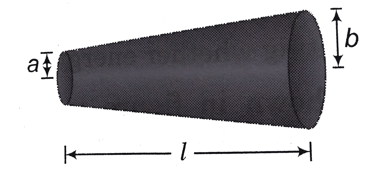
View SolutionA conductor of length `l` has a non-uniform cross-section. The radius of cross-section varies linearly from `a` to `b`. The resistivity of the material is `rho`. Find the resistance of the conductc across its ends.
View SolutionIf a battery of emf `E` and internal resistance `r` is connected across a load of resistance `R`. Shot that the rate at which energy is dissipated in `R` is maximum when `R = r` and this maximur power is `P = E^2//4r`.
View SolutionTwo identical batteries each of emf `E= 2` volt and internal resistance `r=1` ohm are available `t`. produce heat in an external resistance by passing a current through it. What is the maximum power that can be developed across an external resistance `R` using these batteries?
View SolutionTwo coils connected in series have resistance of `600K Omega` and `300 Omega` at `20^@C` and temperature coefficient of` 0.001` and `0.004 (.^@C)^-1` respectively. Find resistance of the combination at a temperature of `50^@C`. What is the effective temperature coefficient of combination?
View SolutionAn aluminium wire `7.5 m` long is connected in parallel with a copper wire `6 m` long. When a current of `5 A` is passed through the combination, it is found that the current in the aluminium wire is `3 A`. The diameter of the aluminium wire is `1 mm`. Determine the diameter of the copper wire. Resistivity of copper is `0.017 muOmega-m` and that of the aluminium is `0.028 muOmega-m`.
View SolutionThe potential difference between two points in a wire `75.0 cm` apart is `0.938 V`, when the current density is `4.40 xx 10^7 A// m^2`. What is
(a) the magnitude of `E` in the wire?
(b) the resistivity of the material of which the wire is made?
View SolutionA rectangular block of metal of resistivity `p` has dimensions `d xx 2d xx 3d`. A potential difference `V` is applied between two opposite faces of the block.
(a) To which two faces of the block should the potential difference `V` be applied to give the maximum current density? What is the maximum current density?
(b) To which two faces of the block should the potential difference `V` be applied to give the maximum current? What is this maximum current?
View SolutionAn electrical conductor designed to carry large currents has a circular cross-section `2.50 mm` in diameter and is `14.0 m` long. The resistance between its ends is `0.104 Omega` .
(a) What is the resistivity of the material?
(b) If the electric field magnitude in the conductor is `1.28V//m`, what is the total current?
(c) If the material has `8.5 x 10^28` free electrons per cubic metre, find the average drift speed under the conditions of part (b).
View SolutionThe resistance of a copper wire and an iron at `20^@C` are `4.1 Omega` and `3.9Omega` respectively. Neglecting any thermal expansion, find the temperature at which resistane of both are equal.
`alpha_(Cu)=4.0xx10^-3K^-1` an `alpha_(Fe)=5.0xx10^-3K^-1`
View SolutionFind the current supplied by the battery in the circuit shown in figure.
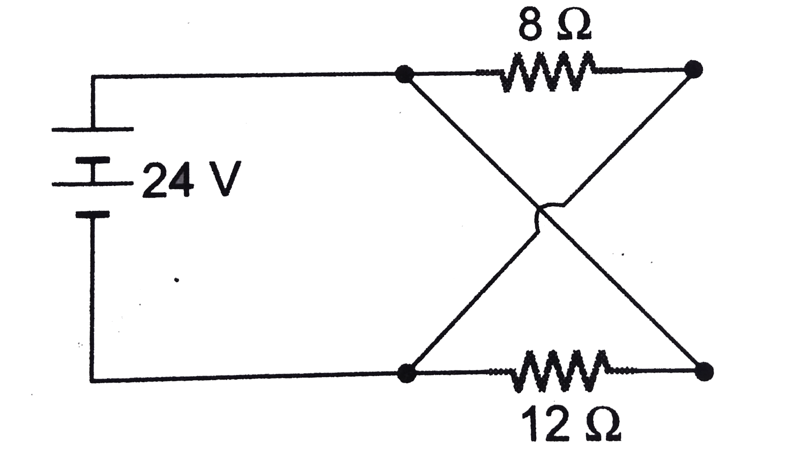
View SolutionCalculate battery current and equivalent resistance of the network shown in figure.
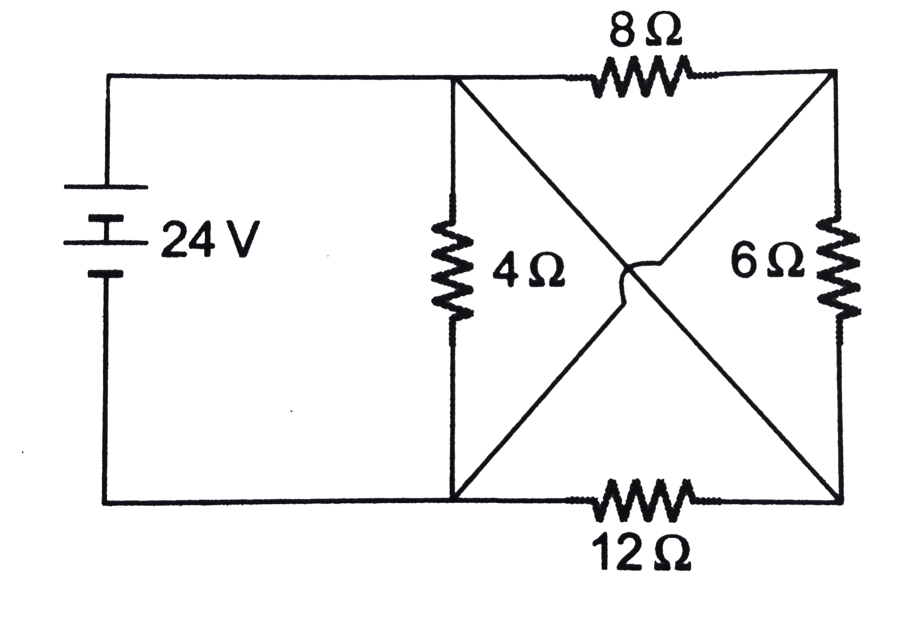
View SolutionCompute total circuit resistance and battery current as shown in figure.
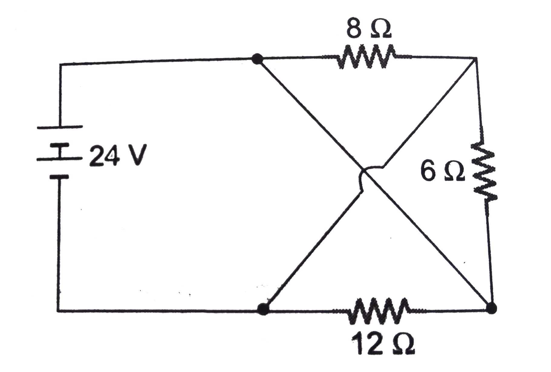
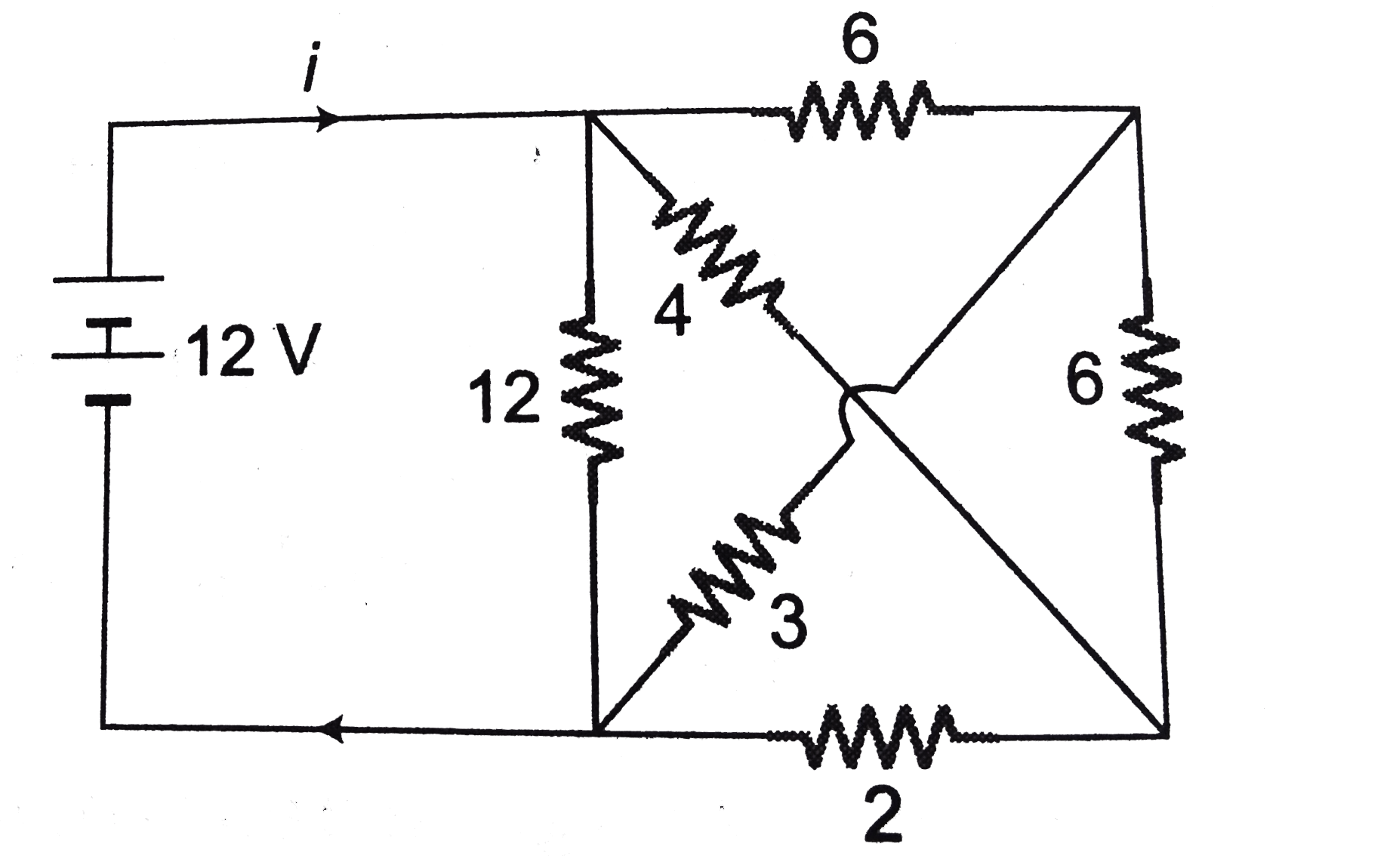
View SolutionCompute the value of battery current in shown in figure. All resistance are in ohm.
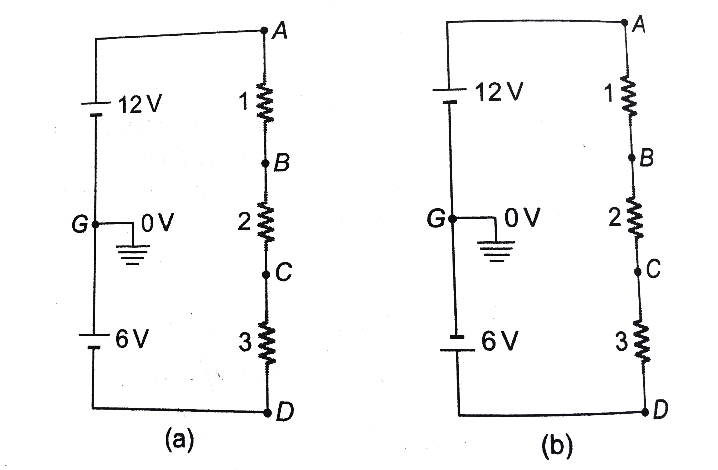
View SolutionCalculate the potentials of points `A, B,C` and `D` as shown in Fig. a. What would be the new potential values if connections of `6 V` battery are reversed as shown in fig b. All resistance are on ohm.
View SolutionGive the magnitude and polarity of the following voltages in the circuit of figure:
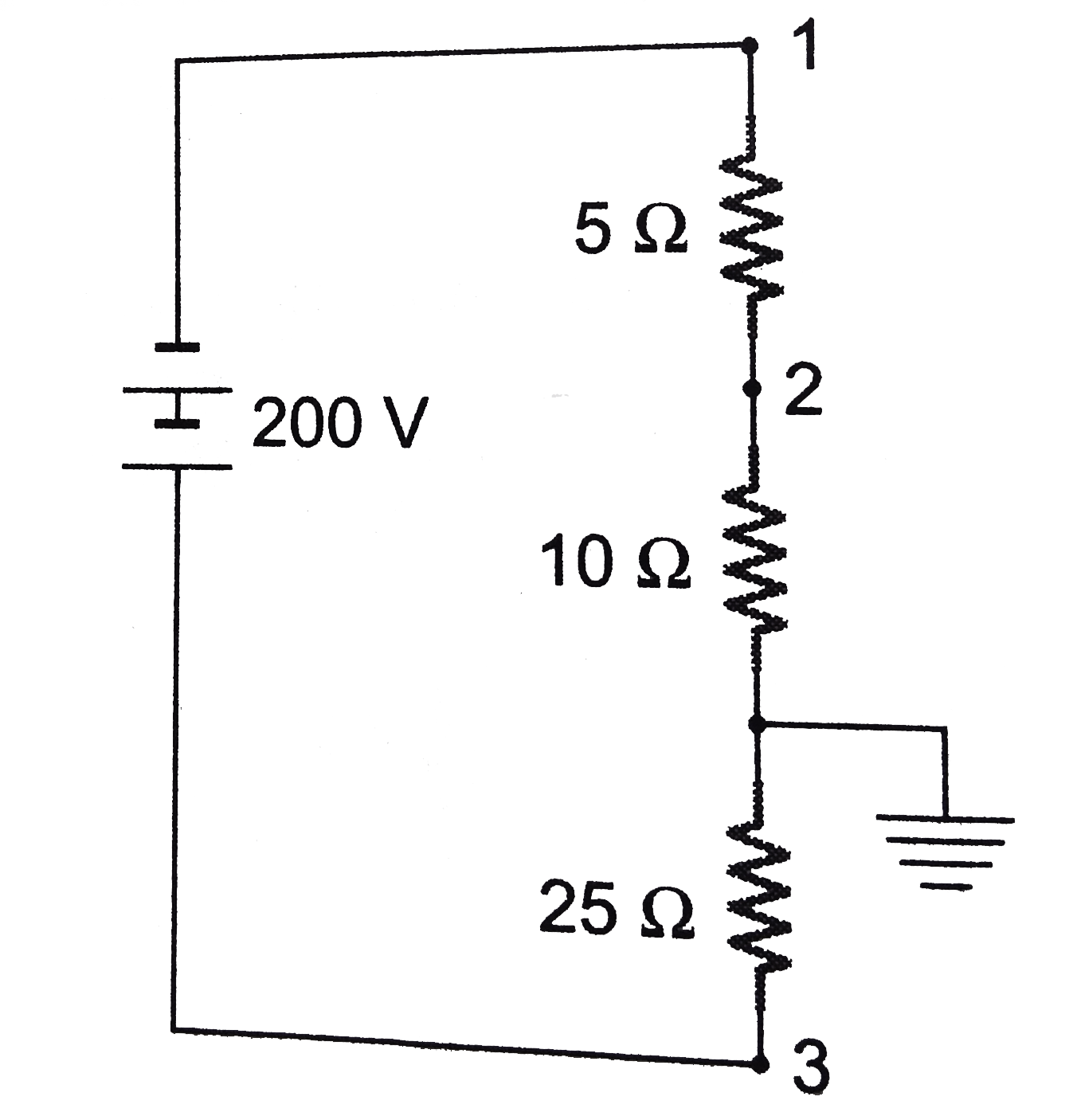
i. `V_1` ii. `V_2` iii. `V_3` iv. `V_(3-2)`
v. `V_(1-2)`
`V_(1-3)`
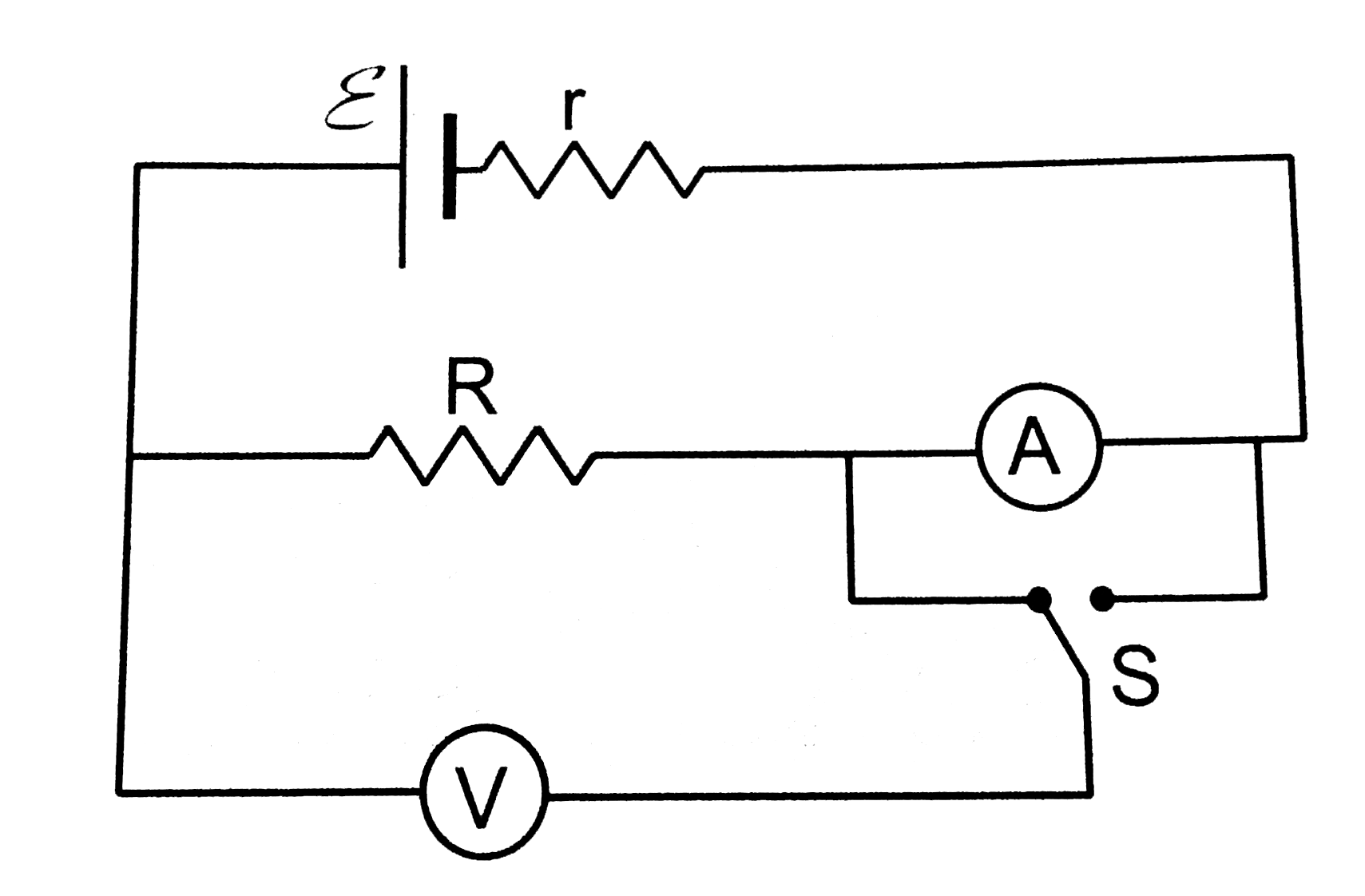
View SolutionThe emf `(epsilon)`and the internal resistance r of the battery shown in figure are 4.3V and `1.0 Ohm` respectively.The external resistance R is `50 ohm`.The resistances of the ammeter and voltmeter are `2.0 ohm and `200ohm respectively.(a)Find the reading of the two meters.(b) The switch is thrown to the other side, What will be the readings of the two meters now?
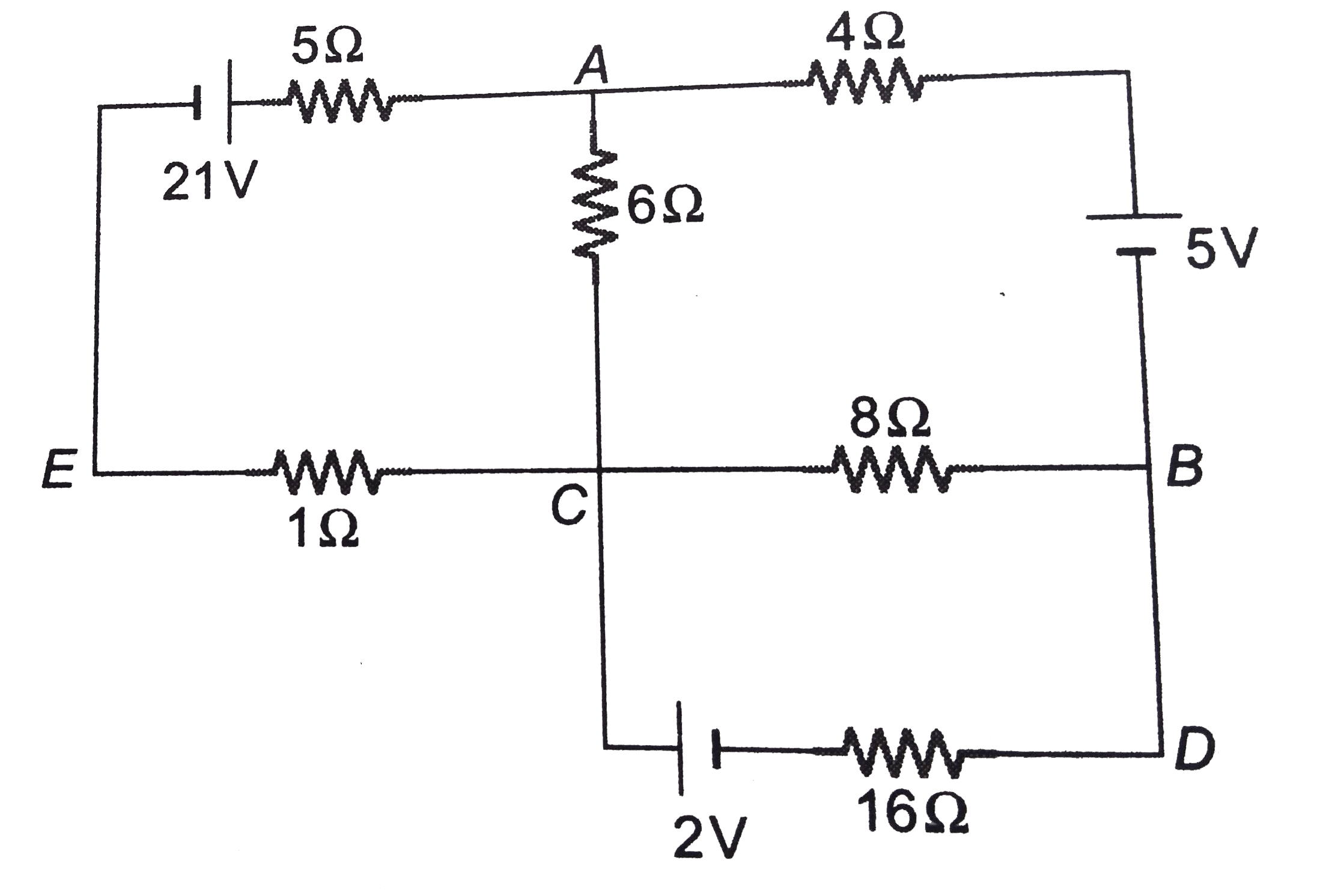
View SolutionFind the current in each branches of the circuit.
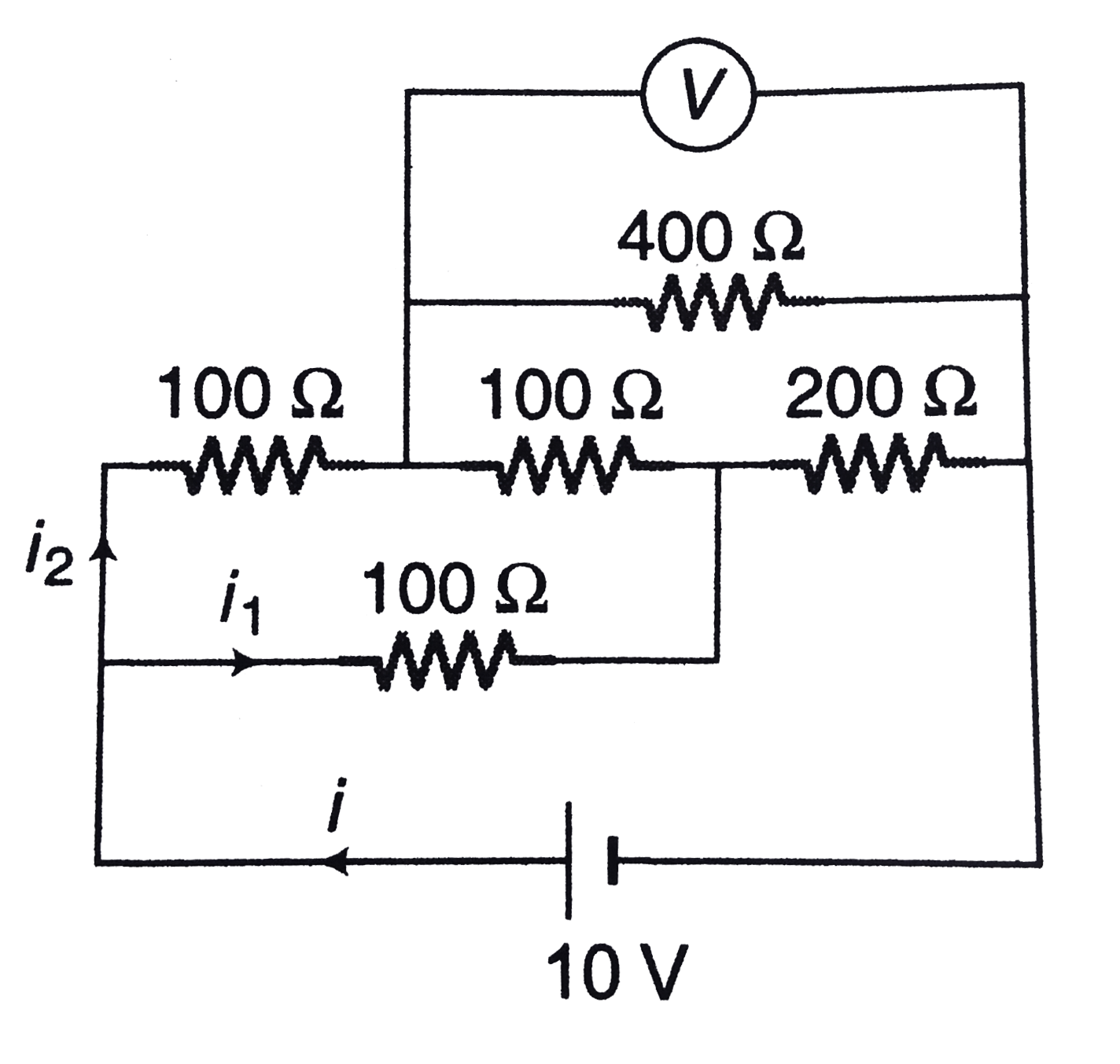
View SolutionAn electrical circuit is shown in figure. Calculate the potential difference across the resistor of `400 Omega` as will be measured by the voltmeter Vof resistance `400 Omega` either by applying Kirchhoff's rules or otherwise.
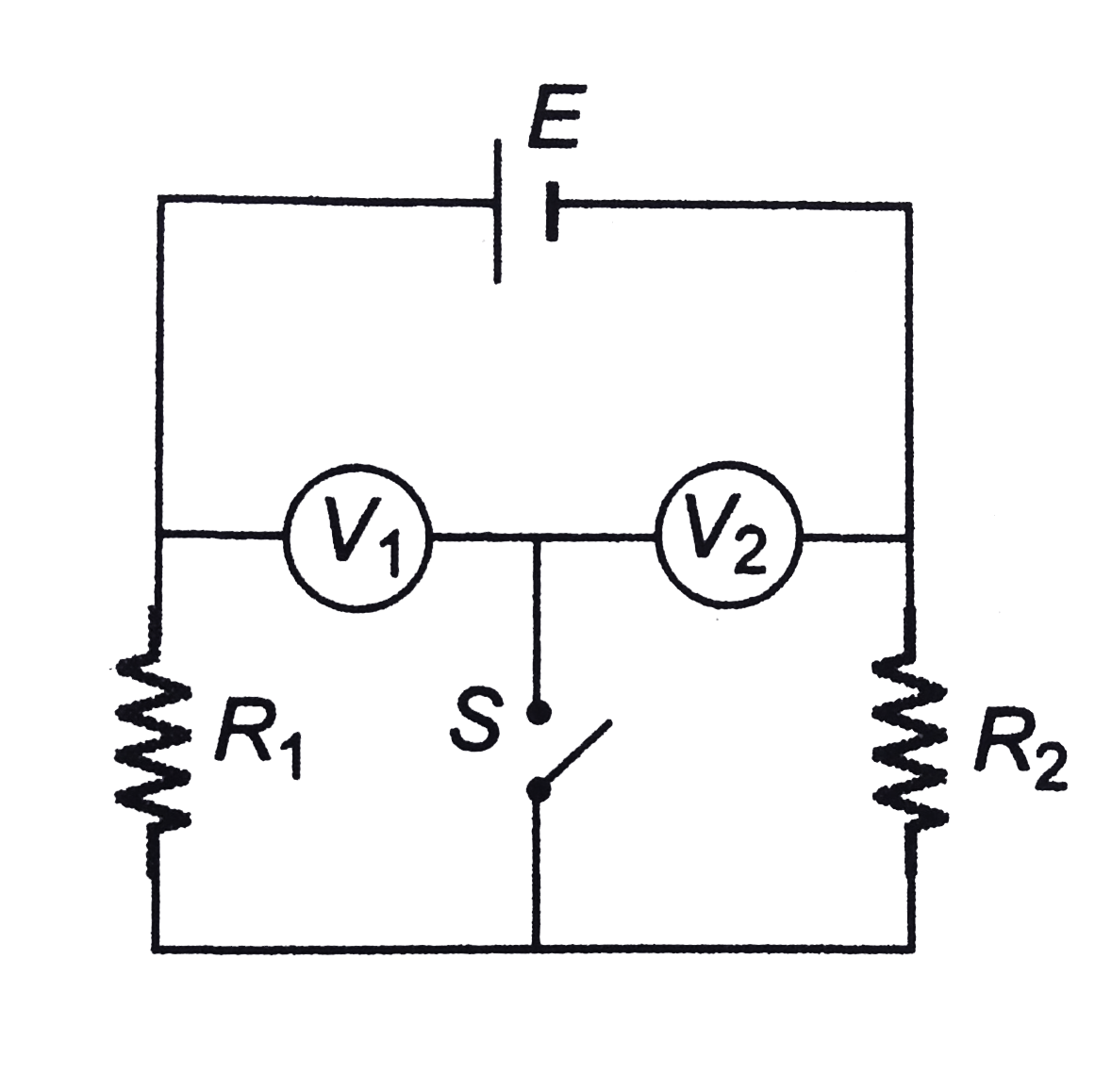
View SolutionIn the circuit shownin figure `V_1` and `V_2` are two voltmeter of resistances `3000 Omega` and ` 2000 Omega` respectively. In additions `R_1=2000Omega`, `R_2=3000omega` and `E=200 V` then
a. Fid the reading of voltmeters `V_1` and `V_2` when
i. switch `S` is open
ii. Switch `S` is closed
b. Current through `S`, when it is closed (Disregard the resistance of battery)
View SolutionIn figure circuit section `AB` absorbs energy at the rate of `5.0 W` when a current` i =1.0A` passes through it in the indicated direction.
(a) What is the potential difference between points `A` and `B`?
(b) Emf device `X` does not have internal resistance. What is its emf?
(c) What is its polarity (the orientation of its positive and negative terminals)?

View SolutionThe potential difference across the terminals of a battery is `8.4 V` when there is a current of `1.50 A` in the battery from the negative to the positive terminal. When the current is `3.50 Air`, the reverse direction, the potential difference becomes `9.4 V`.
(a) What is the internal resistance of the battery?
(b) What is the emf of the battery?
View SolutionA battery of emf `2.0 V` and internal resistance `0.10 Omega` is being charged with a current of `5.0 A`. Find the potential difference between the terminals of the battery?
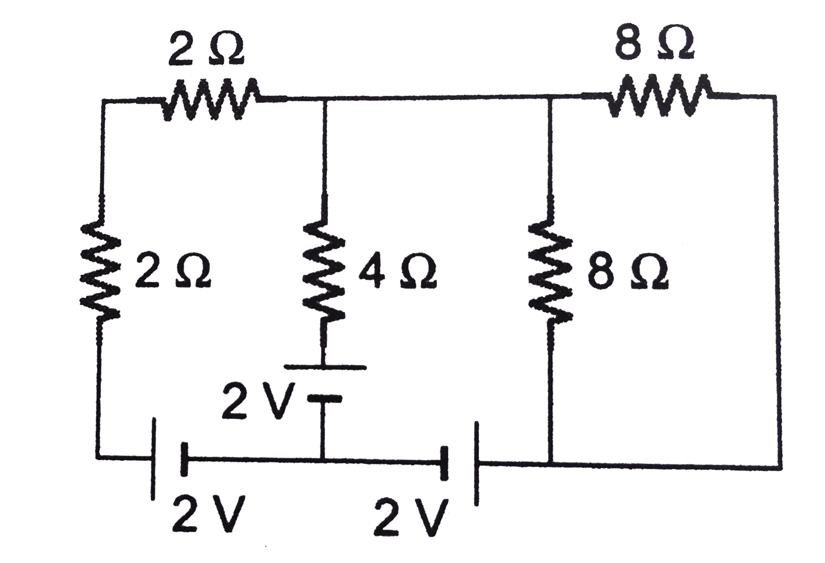
View SolutionFind the currents in different resistors shown in figure
View SolutionA resistance box, a battery and a galvanometer of resistance `G` ohm are connected in series. the galvanometer is shunted by resistance of `S` ohm, find the change in resistance in the be required to maintain the current from the battery unchanged.
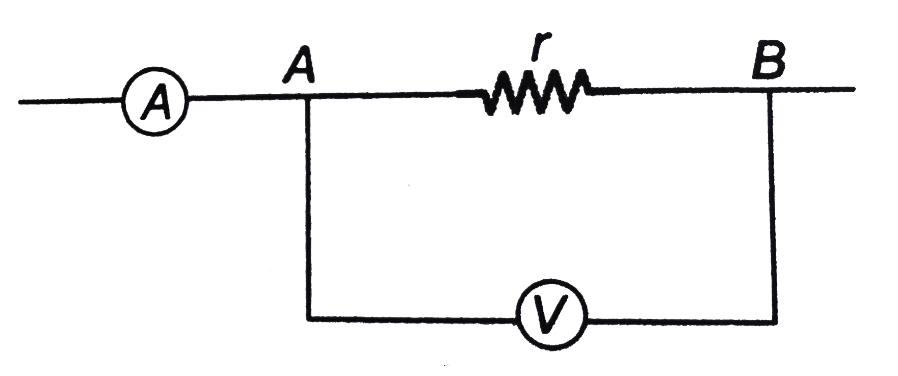
View SolutionDetermine the resistance `r` if an ammeter shows a current of `I = 5 A` and a voltmeter `100 V`. The internal resistance of the voltmeter is `R=2,500Omega`
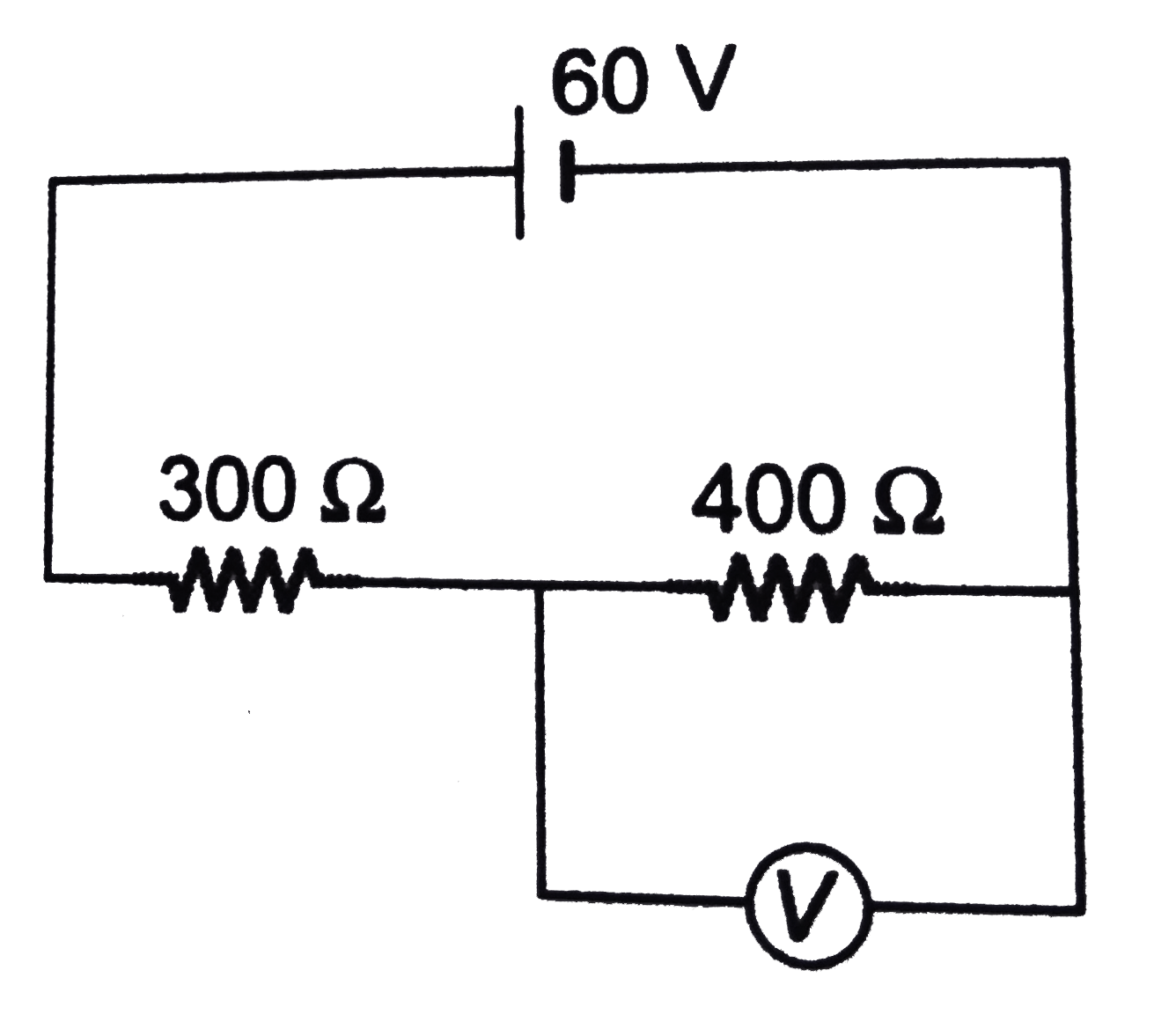
View SolutionIn the circuit, a voltmeter reads `30 V` when it is connected across 400 `Omega` resistance. Calculate what the same voltmeter will read when it is connected across the `300Omega` resistance?
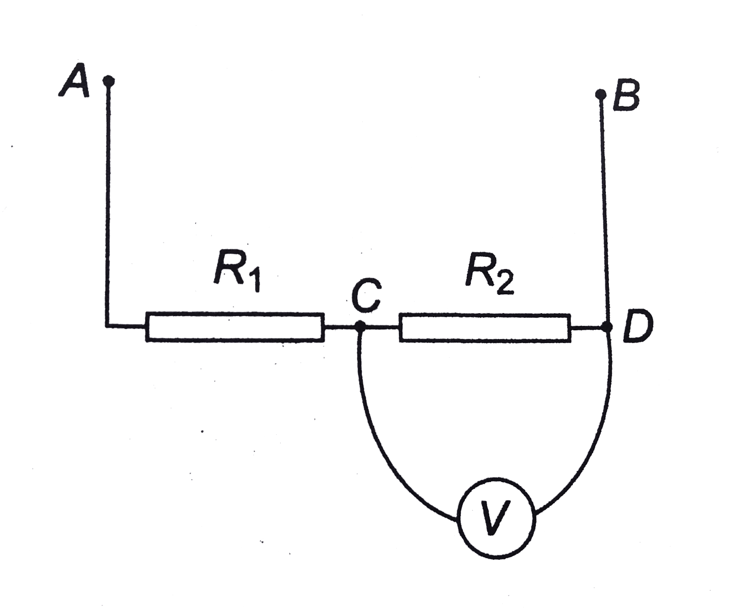
View SolutionResistance `R_1`and `R_2`, each `60 Omega`, are connected in series. The Potential difference between points `A` and `B` is `120 V`. Find the reading of voltmeter connected resistance `r=120Omega`
View SolutionA moving coil galvanometer of resistance `20 Omega` gives a full scale deflection when a current of `1mA` is passed through it. It is to be converted into an ammeter reading `20 A` on full scale. But the shunt of `0.005 Omega` only is available. What resistance should be connected in series with the galvanometer coil?
View SolutionA cell of emf `3.4 V` and internal resistance `3 Omega` is connected to an ammeter having resistance `2Omega` and to an external resistance of `100Omega`. When a voltmeter is connected across the `100 Omega` resistance, the ammeter reading is `0.04 A`. Find the voltage reading by the voltmeter and its resistance. Had the voltmeter been an ideal one what would have been its reading?
View Solution(a) A voltmeter with resistance `R_v` is connected across the terminals of a battery of emf `E` and internal resistance `r`. Find the potential difference measured by the voltmeter.
(b) If` E = 7.50 V` and `r = 0.45 Omega`, find the minimum value of the voltmeter resistance `R_v` so that the voltmeter reading is within `1.0%` of the emf of the battery. (c) Explain why your answer in part (b) represents a minimum value.
View SolutionAn ammeter with resistance `R_A` is connected in series with a resistor R, a battery of emf c and internal resistance `r`. The current measured by the ammeter is `I_A`. Find the current through the circuit if the ammeter is removed so that the battery and the resistor form a complete circuit. Express your answer in terms of `I_A, r, R_A` and `R`. Show that more "ideal" the ammeter, the smaller the difference between this current and the current `I_A`. ltbr. (b) If `R = 3.80 Omega, epsilon = 7.50 V` and `r = 0.45 Omega`, find the maximum value of the ammeter resistance `R_A` so that `I_A` is within `99%` of the current in the circuit when the ammeter is absent. (c) Explain why your answer in part (b) represents a maximum value.
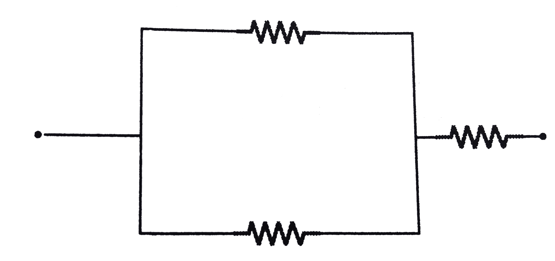
View SolutionEach of three resistors in figure has a resistance of `2.4 Omega` and can dissipate a maximum of 36 W without becoming excessively heated. What is the maximum power the circuit can dissipate?
View SolutionA storage battery with emf `2.6 V` loaded with external resistance produces a current `1 A`. In this case, the potential difference between the terminals of the storage battery equals `2 V`. Find the thermal power generated in the battery and the net power supplied by the battery for external circuit.
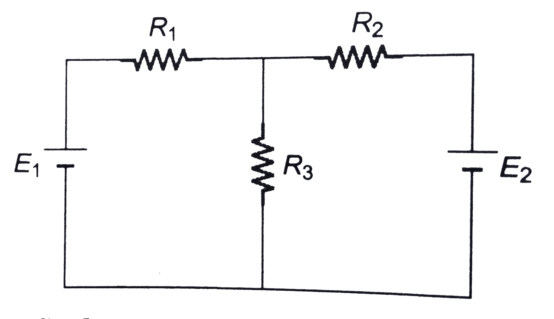
View SolutionIn the circuit shown in figure `E_1=7V,E_2=1 V,R_1=2Omega, R_2=2Omega` and `R_3=3Omega` respectively. Find the power supplied by the two batteries.
View SolutionIn the circuit shown in figure find
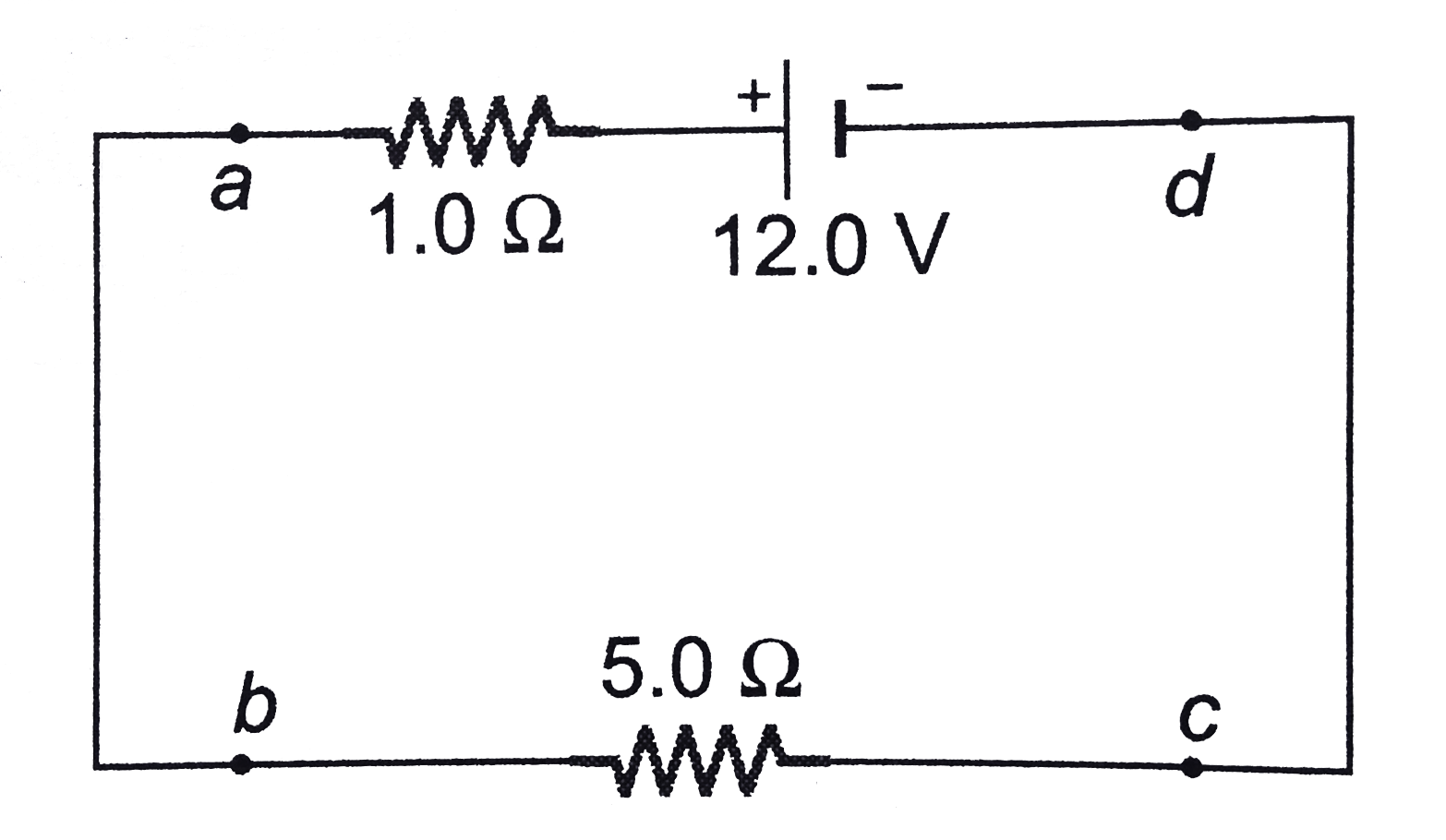
a) the rate of conversion of internal (chemical) energy to electrical energy within the battery
(b) the rate of dissipation of electrical energy in the battery
(c) the rate of dissipation of electrical energy in the external resistor.
View SolutionThree resistors having resistances of `1.60 Omega, 2.40 Omega` and `4.80 Omega` are connected in parallel to a `28.0 V` battery that has negligible internal resistance. Find
(a) the equivalent resistance of the combination.
(b) the current in each resistor.
(c) the total current through the battery.
(d) the voltage across each resistor.
(e) the power dissipated in each resistor.
(f) which resistor dissipates the maximum power the one with the greatest resistance or the least resistance? Explain why this should be.
View SolutionThe power of resistor is the maximum power the resistor can safely dissipate without too rise in temperature. The power rating of a `15 kOmega` resistor is `5.0 W`. What is the maximum allowable potential difference across the terminals of the resistor?
(b) A `9.0 kOmega` resistor is to be connected across a `120 V` potential difference. What power rating is required?
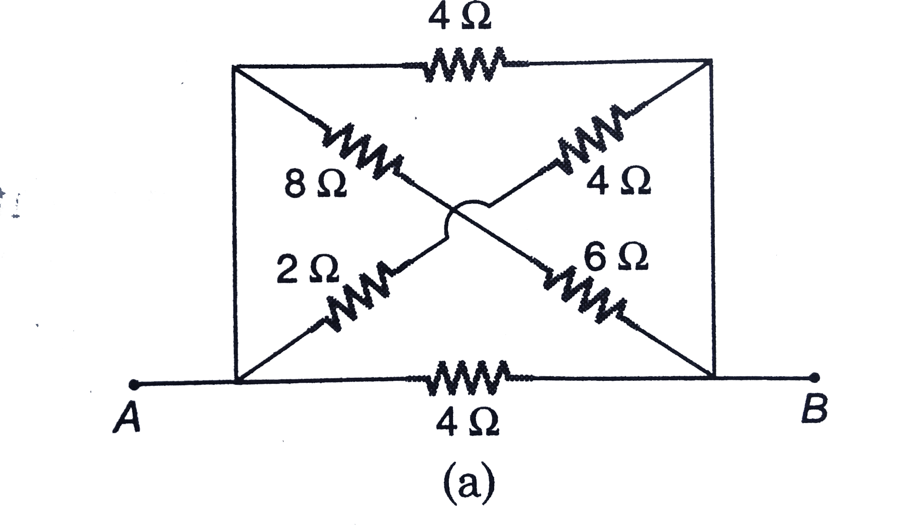
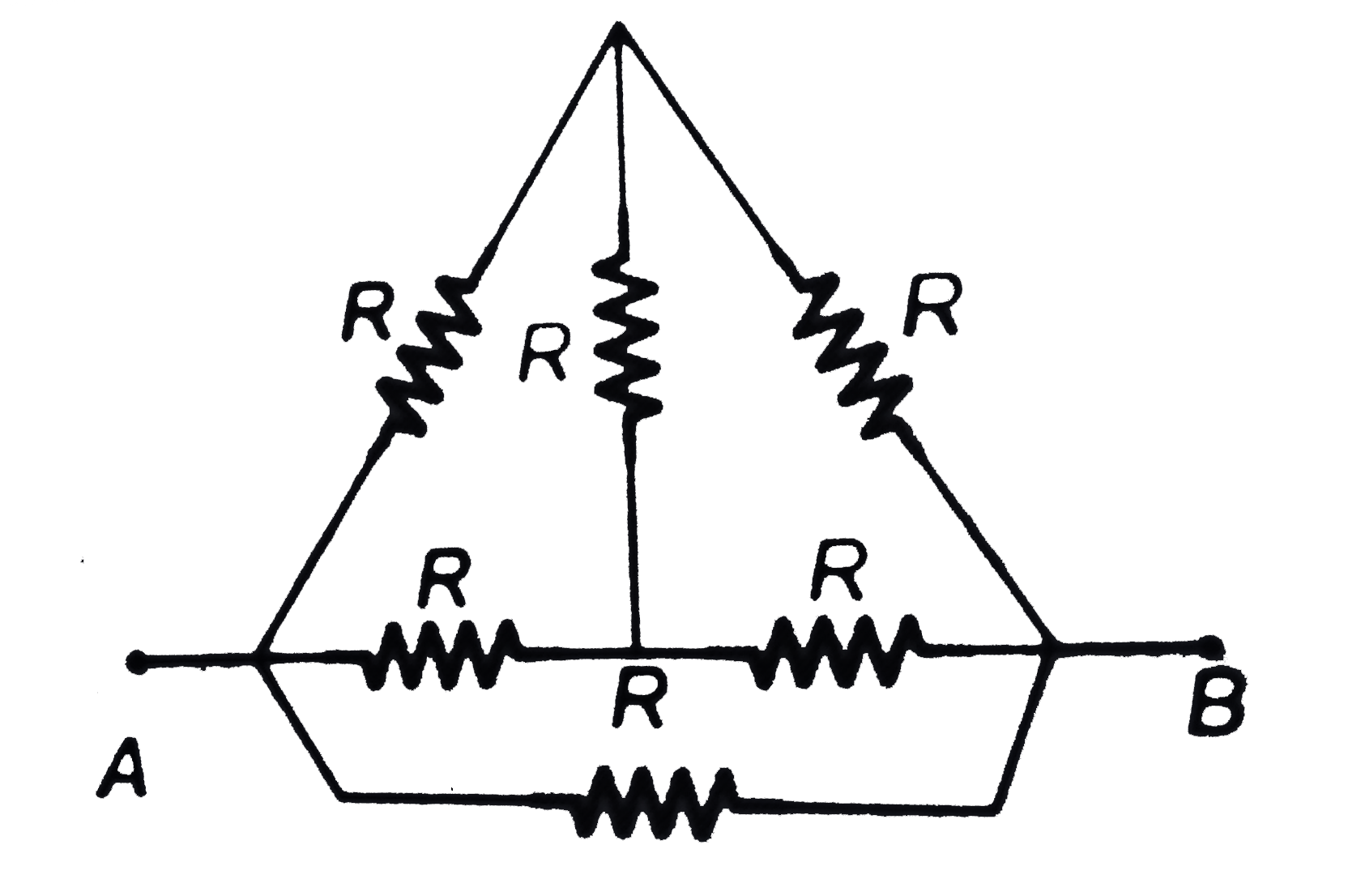
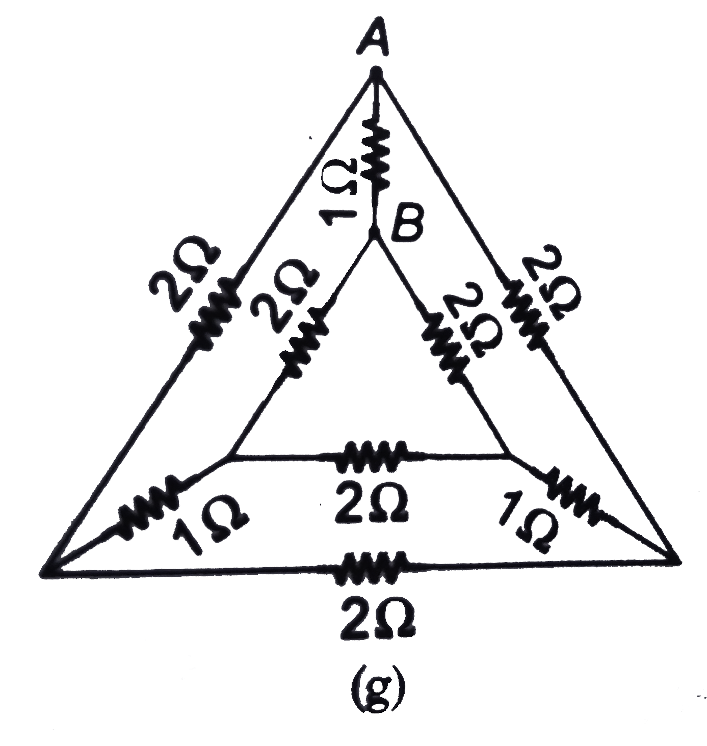
View SolutionFind the equivalent resistance between points `A` and `B` in the following circuits?
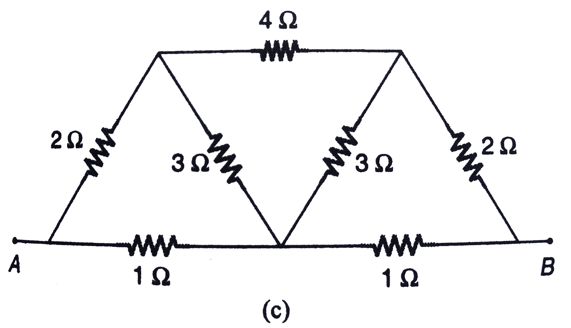
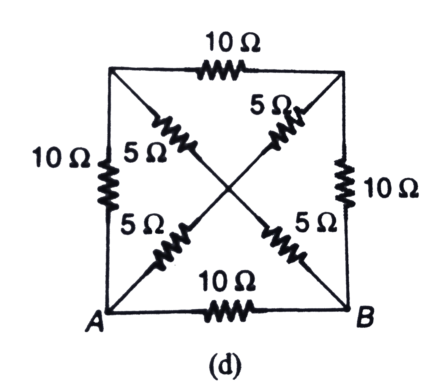
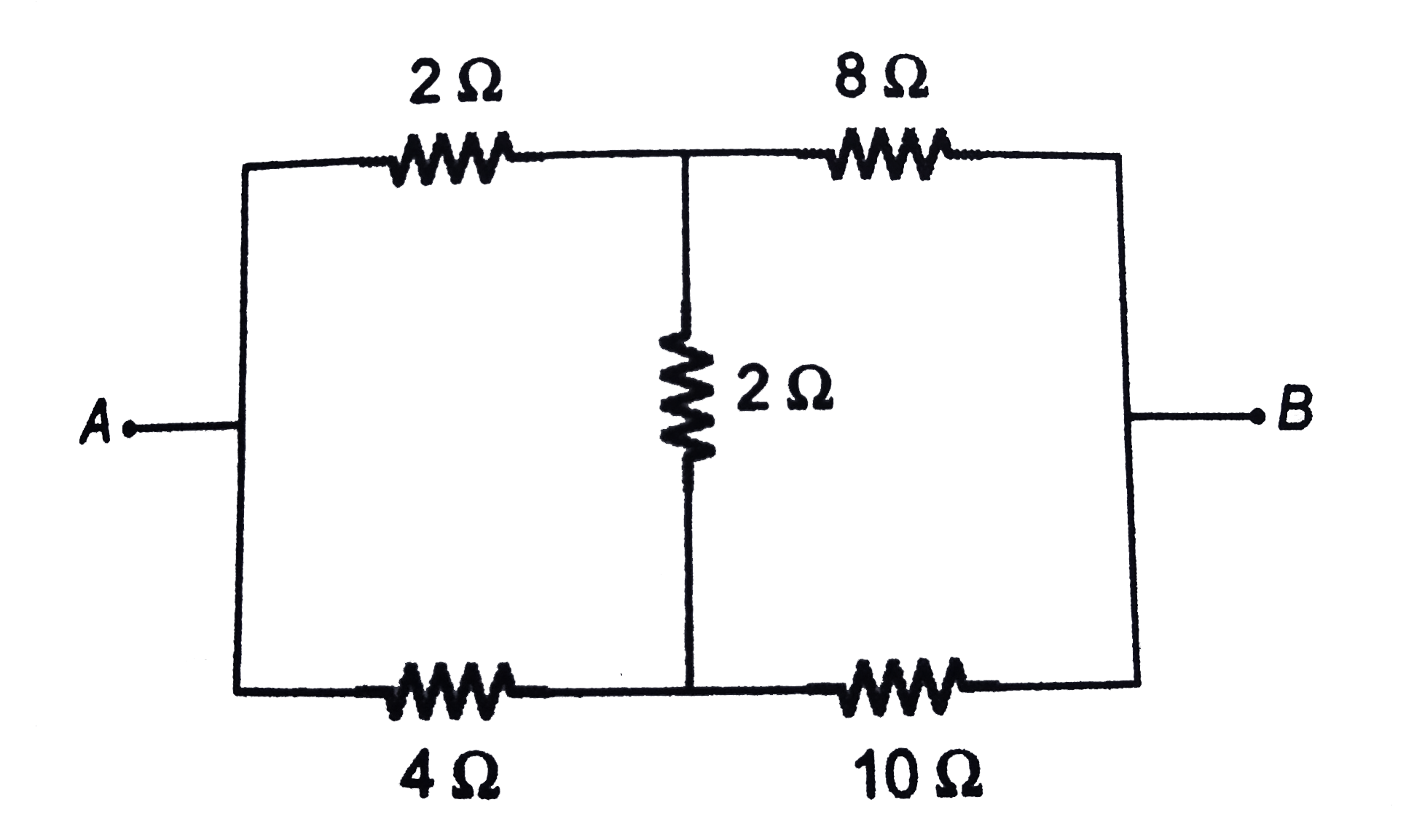
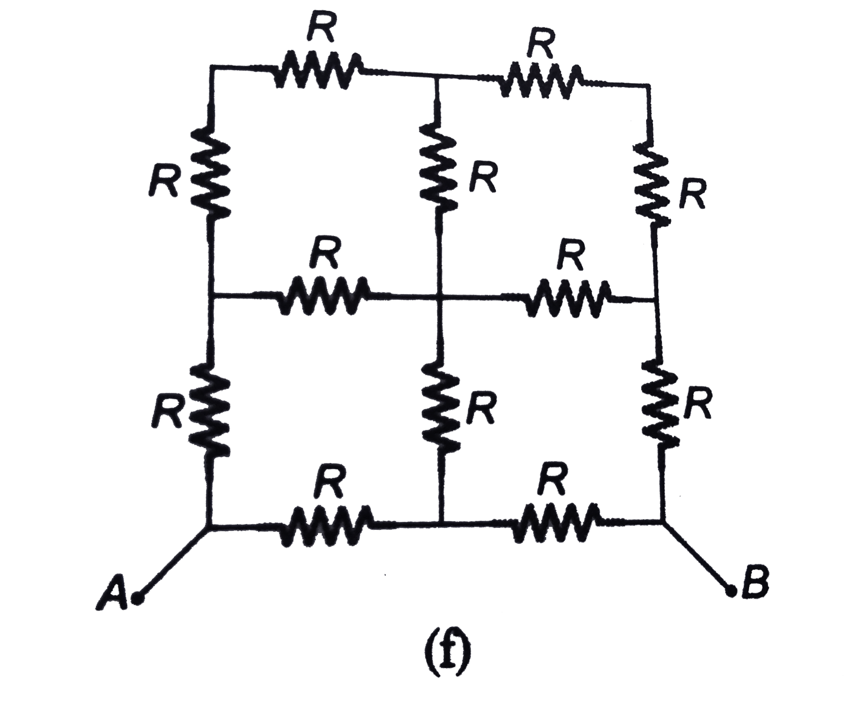
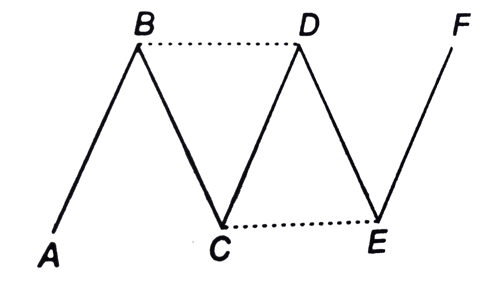
View SolutionWhat will be the change in the resistance of a circuit between `A` and `F` consisting of five identical conductors, if two similar conductors are added as shown by the dashed line in figure?
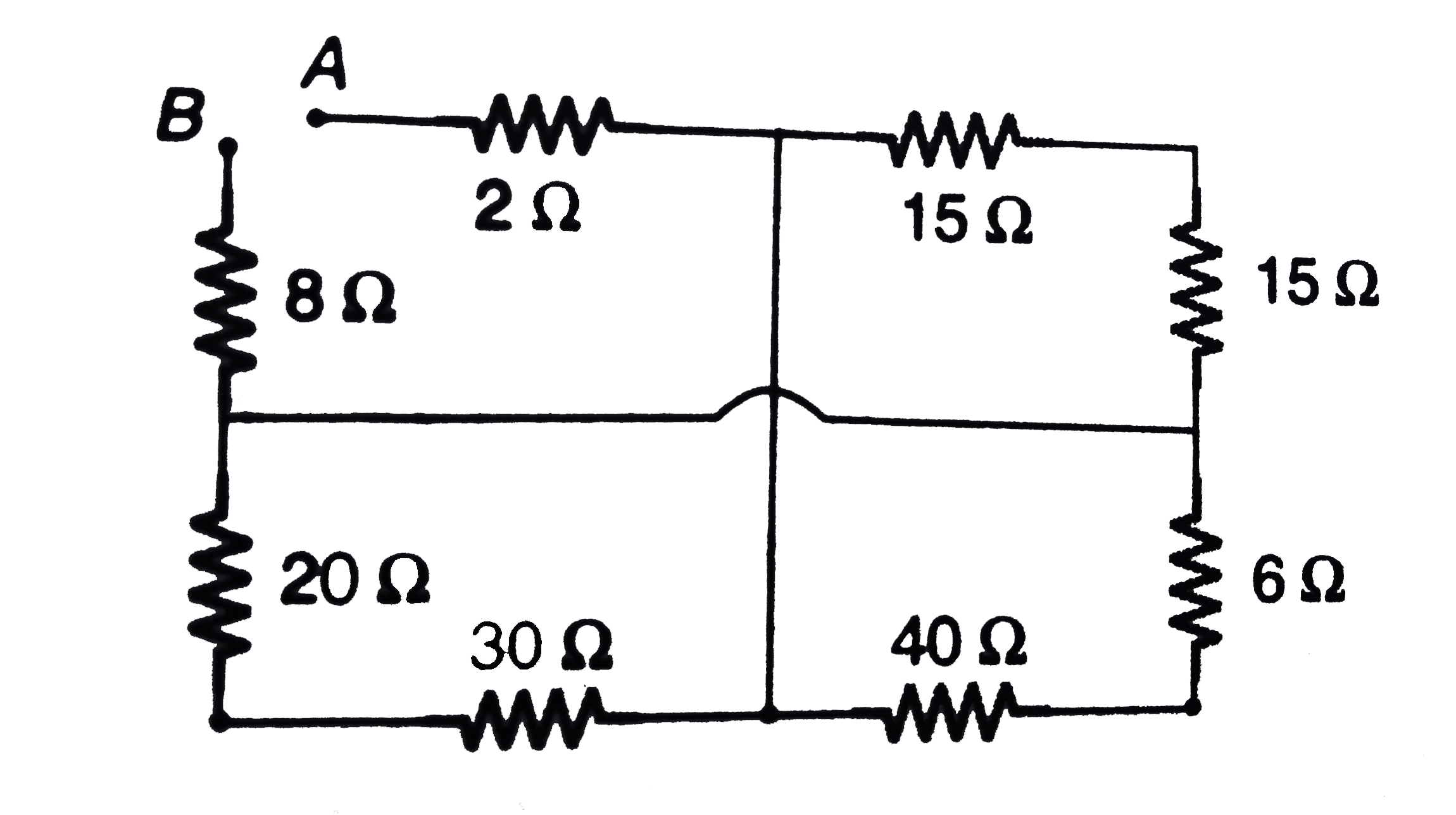
View SolutionFind `R_(AB)` in the circuit shown in figure.
View SolutionFind the equivalent resistance of the networks shown in figure between the points a and b.
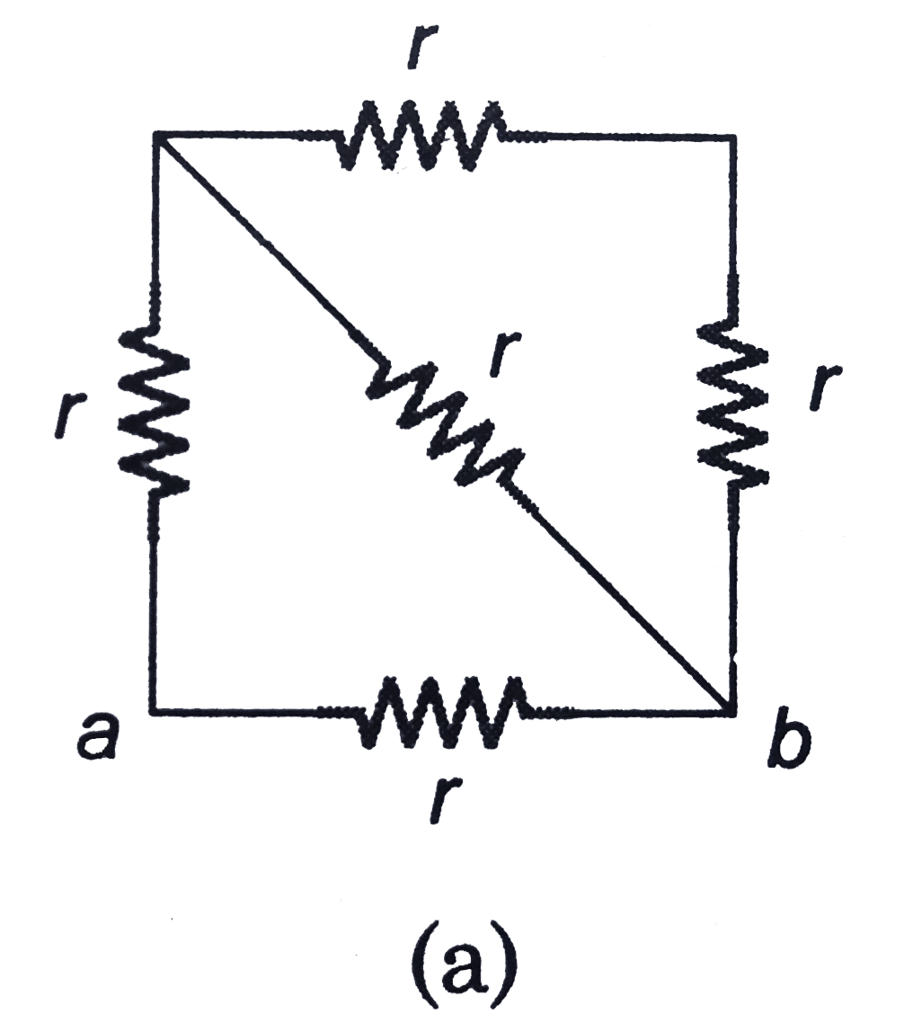
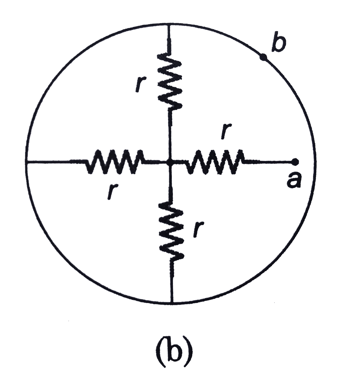
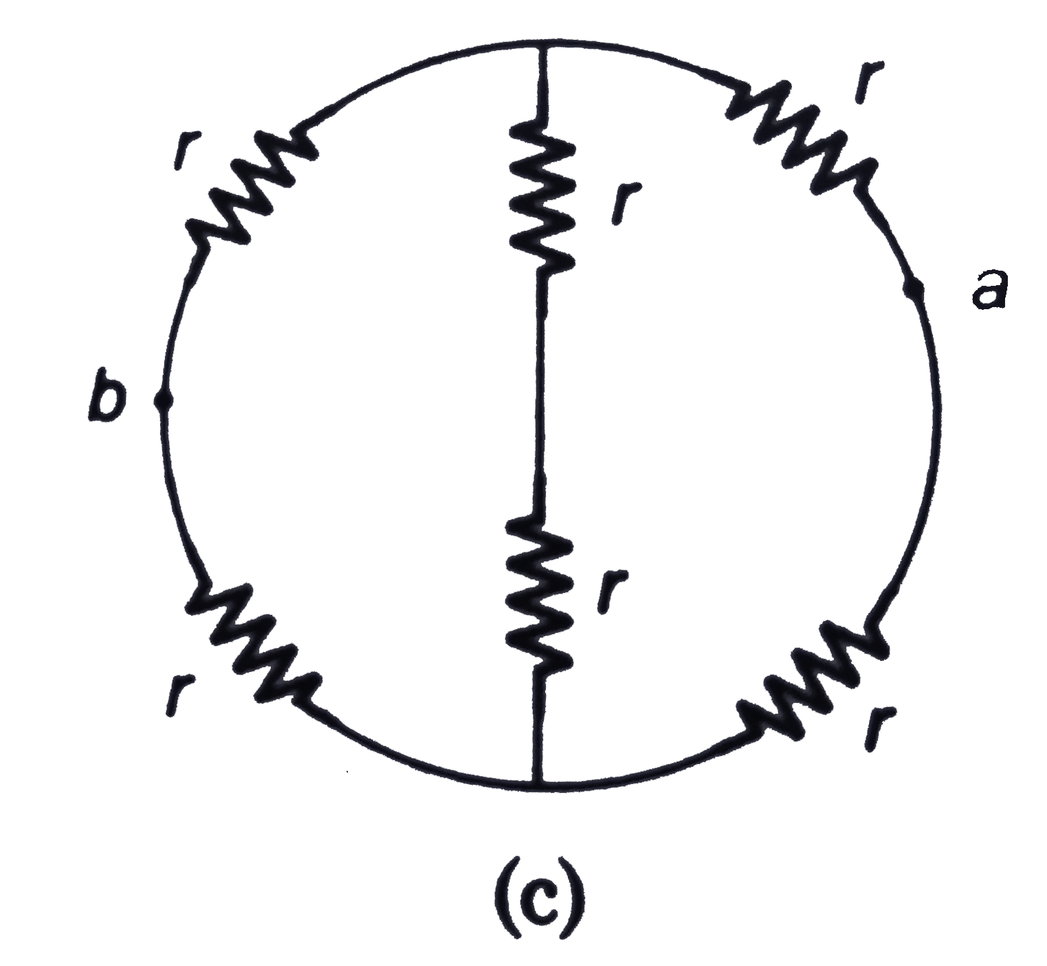
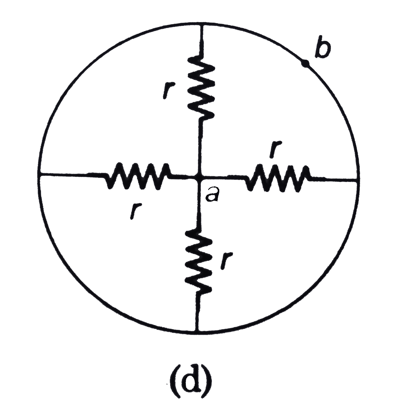
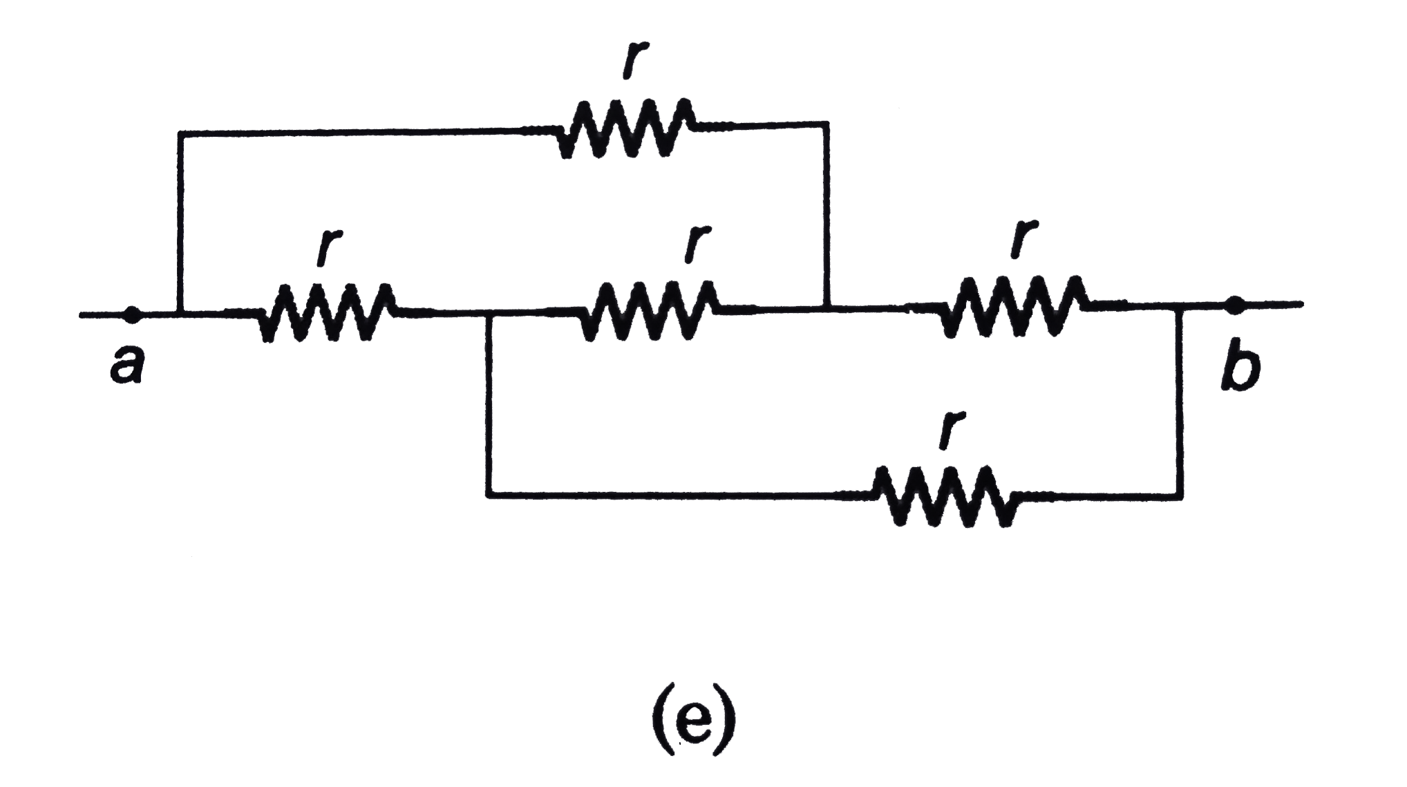
View SolutionFind the equivalent resistance of the circuits shown in figure between the points `a` and `b`. Each resistor has a resistance `r`.
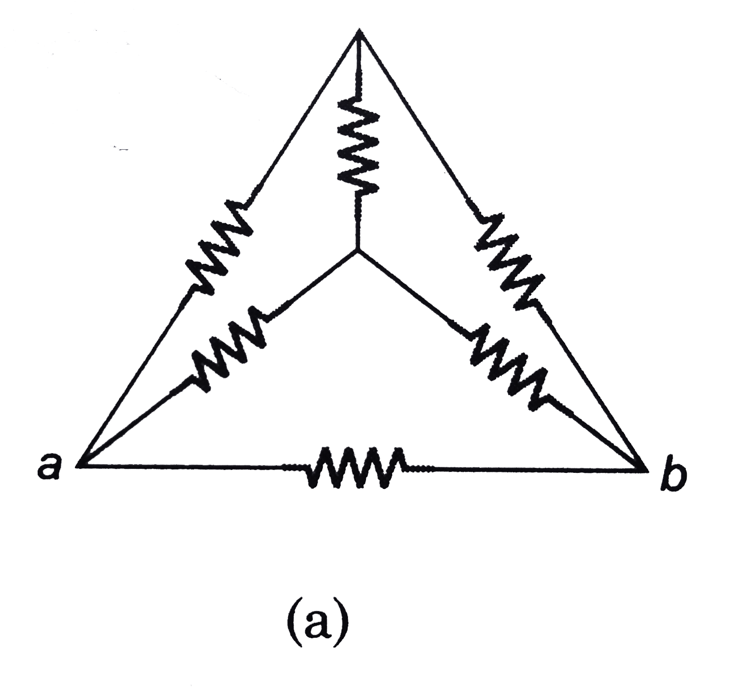
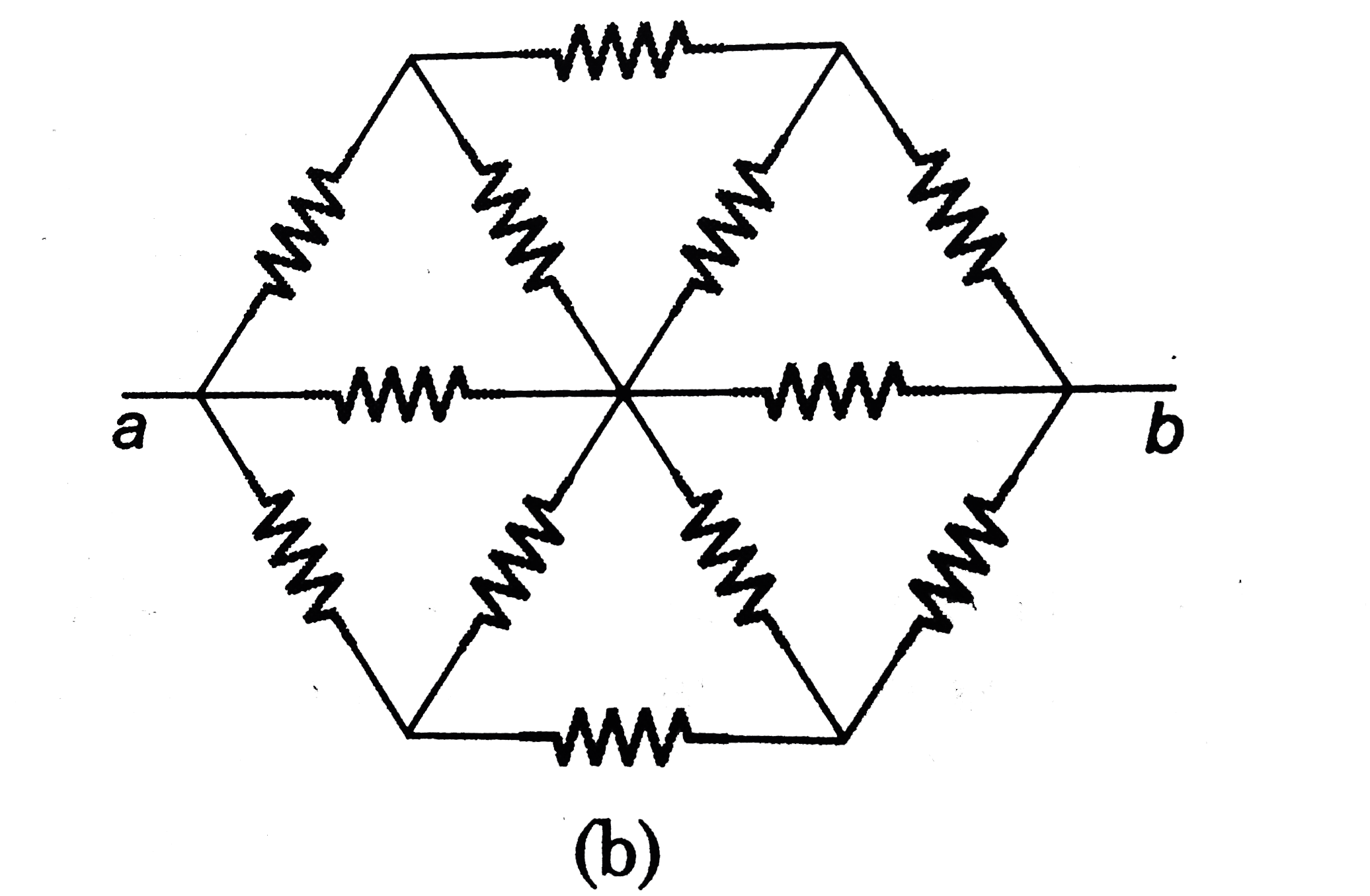
View Solution
Level 1 Subjective questions and complete solutions for chapter CURRENT ELECTRICITY of DC PANDEY ENGLISH of Class 12
All Exercises from DC PANDEY Class 12 PHYSICS CURRENT ELECTRICITY
- B. Assertion and reason
- Check point
- Example
- Example Example Type
- Example Type 1
- Example Type 2
- Example Type 3
- Example Type 4
- Example Type 5
- Example Type 6
- Exercise 23.1
- Exercise 23.10
- Exercise 23.11
- Exercise 23.12
- Exercise 23.13
- Exercise 23.2
- Exercise 23.3
- Exercise 23.4
- Exercise 23.5
- Exercise 23.6
- Exercise 23.7
- Exercise 23.8
- Exercise 23.9
- Level 1 Assertion And Reason
- Level 1 Objective
- Level 1 Subjective
- Level 2 Comprehension Example Type
- Level 2 More Than One Correct
- Level 2 Single Correct
- Level 2 Subjective
- Match the columns
- Medical entrances gallery
- Miscellaneous Examples
- OBJECTIVE_TYPE
- Taking it together