Complete Solutions to Check point of chapter CURRENT ELECTRICITY of Class 12 book with complete answers and questions
| Class 12 | PHYSICS |
| Chapter | CURRENT ELECTRICITY |
| DC PANDEY NEET | Check point |
| Number Of Questions | 70 |
| Academic Year | 2023-24 |
The current flowing through wire depends on time as, `I = 3t^(2) + 2t + 5`
The charge flowing through the cross - section of the wire in time `t = 0` to `t = 2` second is
View SolutionThe charge of an electron is `1.6 × 10^(-19) C` . How many electrons strike the screen of a cathode ray tube each second when the beam current is 16 mA
View SolutionA conductor carries a current of `0.2 A`. Find the amount of charge that will pass through the cross-section of the conductor in `30 s`. How many electrons will flow in this time interval if the charge on one electron is `1.6 xx 10^-19 C` ?
View SolutionIn a closed circuit, the current `I` (in ampere) at an instant of time t (in second) is given by `I = 4-0.08t`. The number of electrons flowing in 50 s through the cross-section of the conductor is
View SolutionDrift velocity `v_(d)` varies with the intensity of electric field as per their relation
View SolutionWhen the current i is flowing through a conductor, the drift velocity is v . If 2i current is flowed through the same metal but having double the area of cross-section, then the drift velocity will be
View SolutionA metallic resistor is connected across a battery.If the number of collisions if the free electrons with the lattice is somehow decreased in the resistor (for example,by cooling it ),the current will
View SolutionWhen current flows through a conductor, then the order of drift velocity of electrons will be
View SolutionThe drift velocity does not depend upon
View SolutionThe number density of free electrons in a copper conductor estimated in Example 3.1 is `8.5 xx 10^(28) m^(-3)`. How long does an electron take to drift from one end of a wire 3.0 m long to its other end? The area of cross-section of the wire is `2.0 xx 10^(-6) m^(2)` and it is carrying a current of 3.0 A.
View SolutionCalculate the amount of charge flowing in 2 minutes in a wire of resistance `10 Omega` when a potential difference of 20 V is applied between its ends
View SolutionIf n, e, `tau`, m, are representing electron density charge, relaxation time and mass of an electron respectively then the resistance of wire of length l and cross sectional area A is given by
View SolutionThe following four wires of length L and radius r are made of the same material. Which of these will have the largest extension, when the samne tersion is applied?
View SolutionCarbon resistors, used in electronic circuits are marked for their value of resistance and tolerance by a colour code. A given resistor has colour scheme brown, red, green and gold. Its value in ohm is
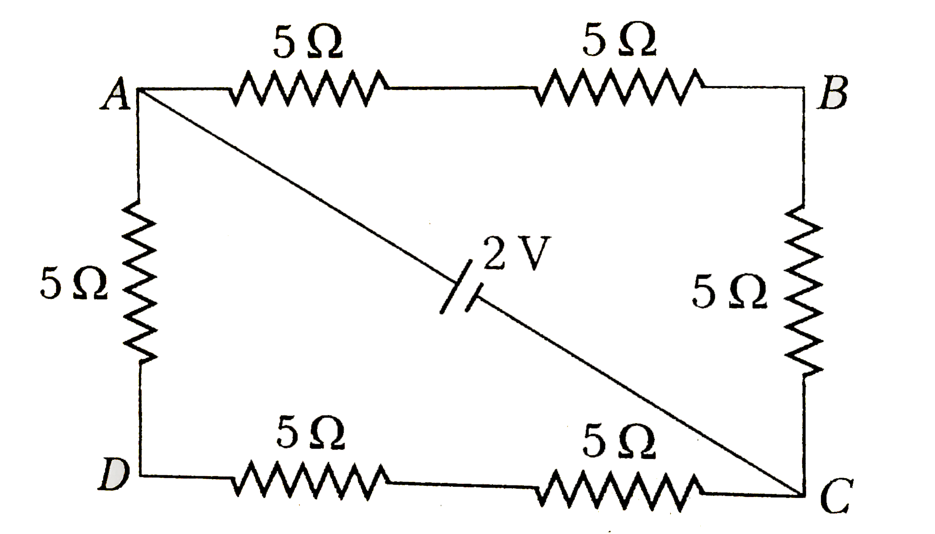
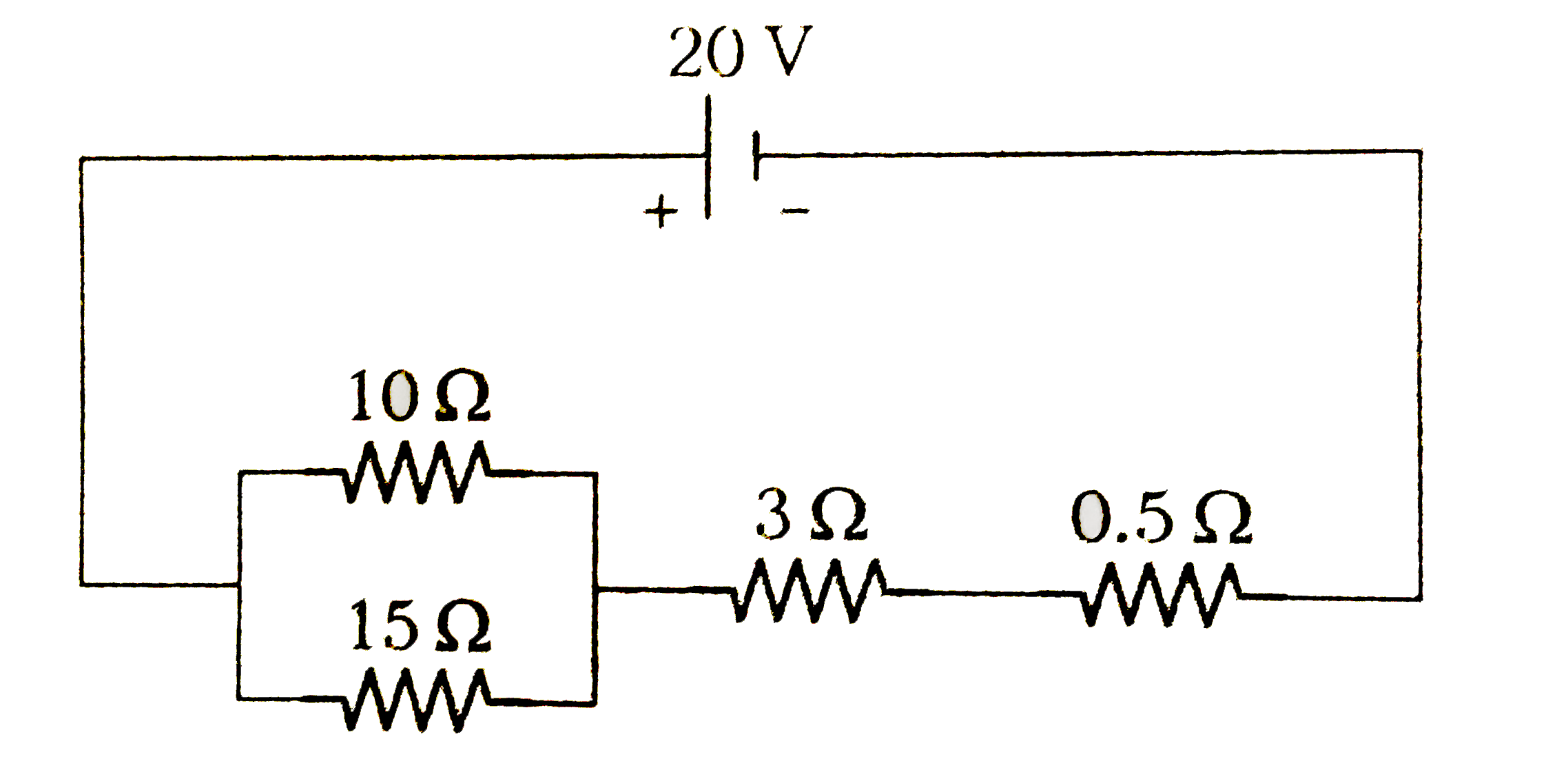
View SolutionThe potential difference between points A and B of the following figure is
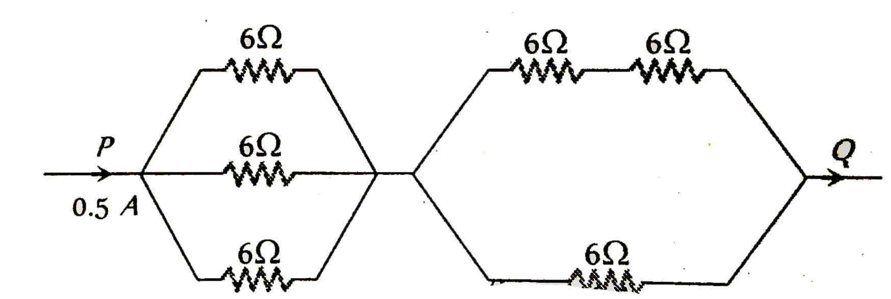
View SolutionResistances of 6 ohm each are connected in the manner shown in adjoining figure. With the current 0.5 ampere as shown in figure, the potential difference `V_(P) - V_(Q)` is
View SolutionIn the figure given below, the current passing through `6Omega` resistor is

View SolutionCurrent through `3Omega` resistor is 0.8A, then potential drop through `4Omega` resistor is
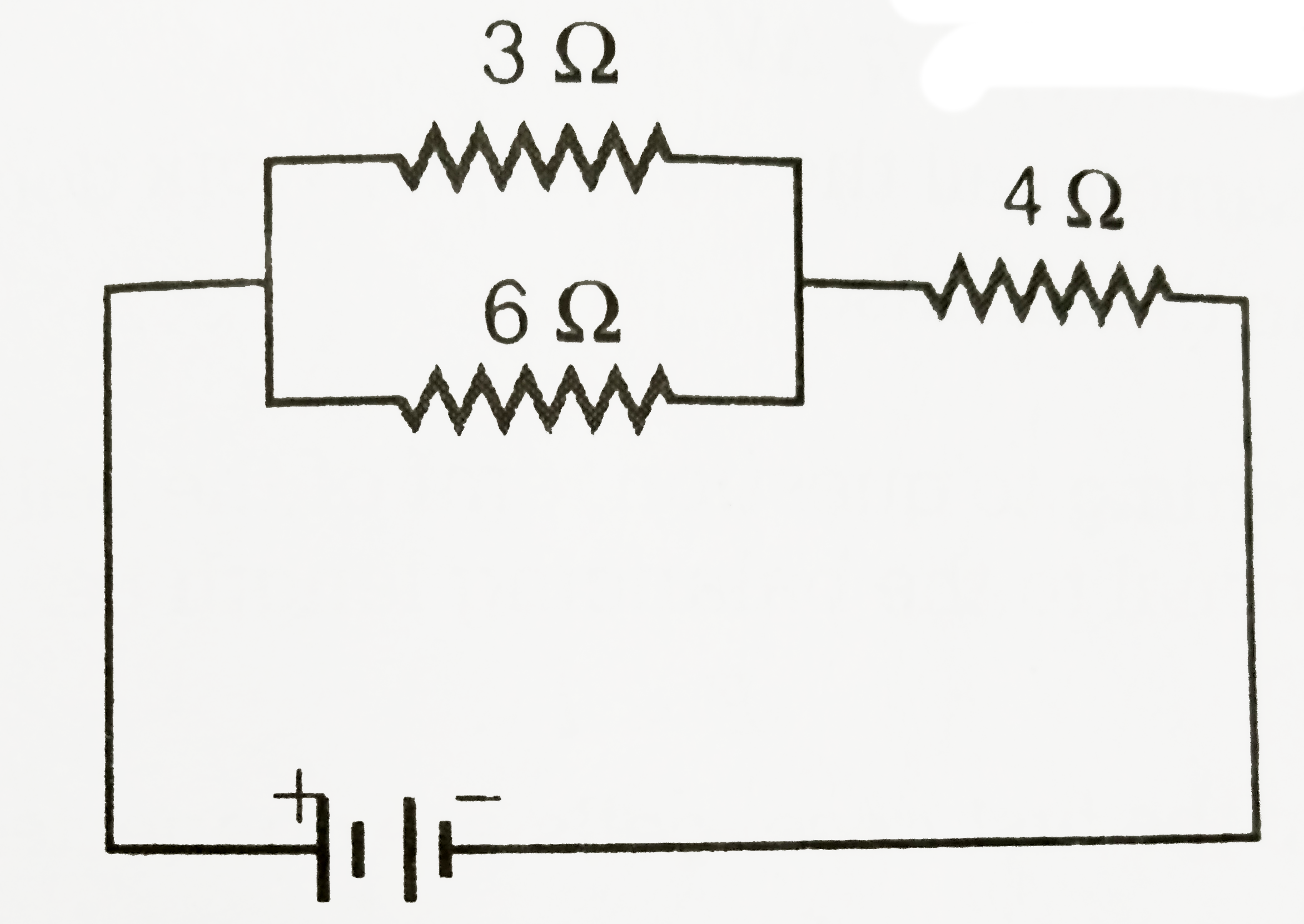
View SolutionCurrent I as shown in the circuit will be
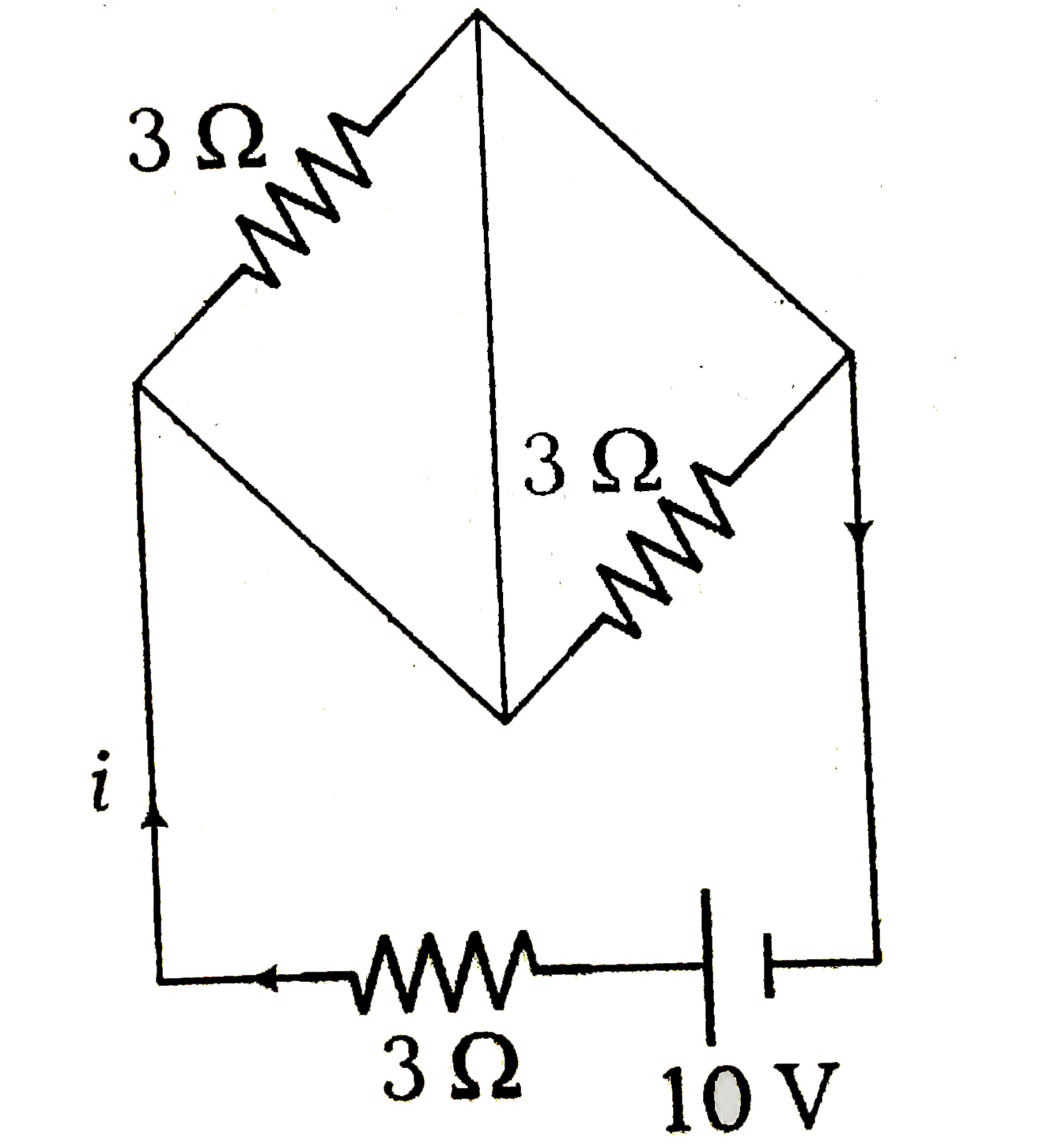
View SolutionIn the circuit, the current flowing through `10Omega` resistance is
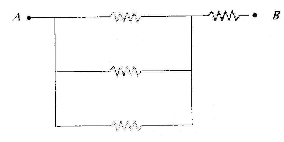
View SolutionIf all the resistors shown have the value 2 ohm each, the equivalent resistance over AB is
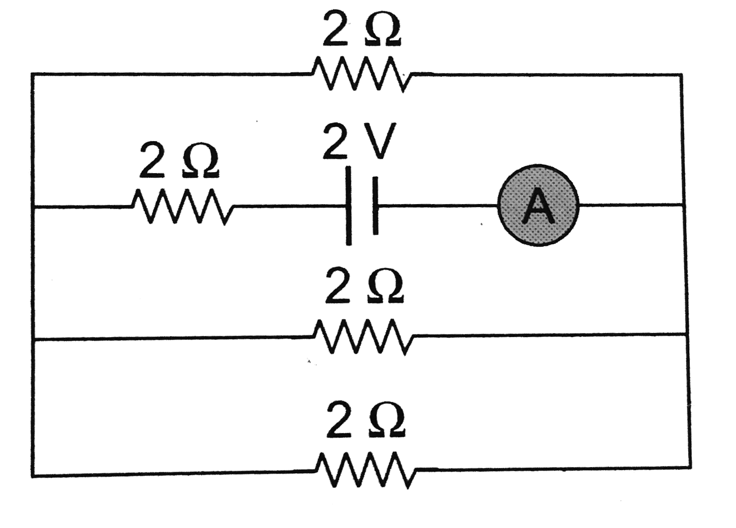
View SolutionThe reading of the ammeter as per figure shown is
View SolutionThe current from the battery in circuit diagram shown is
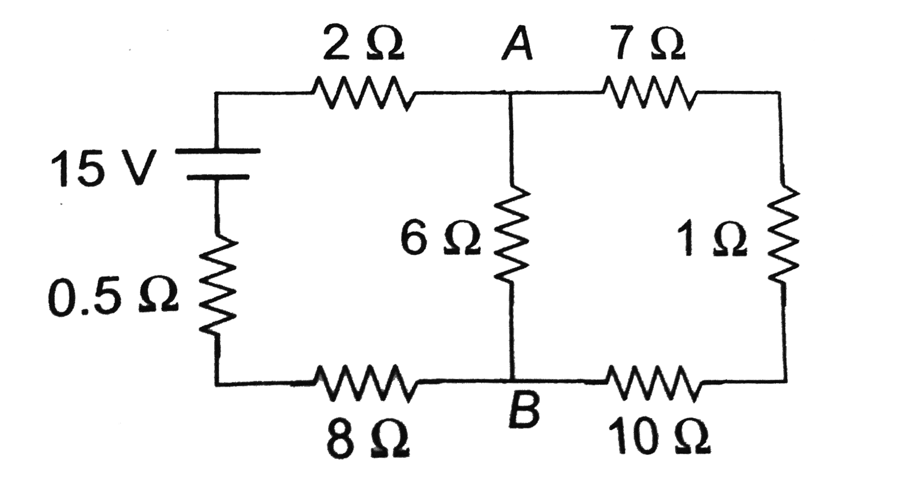
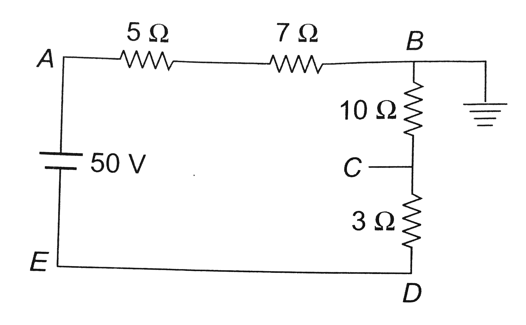
View SolutionIn the circuit shown, the point `B` is earthed. The potential at the point `'A'` is
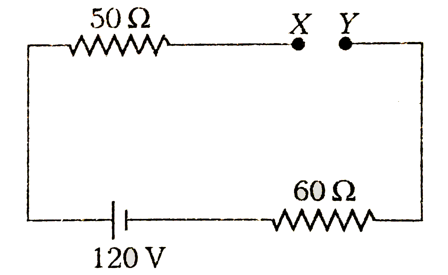
View SolutionIn the circuit shown, potential difference between X and Y will be
View SolutionA current of 2.0 ampere passes through a cell of e.m.f. 1.5 volts having internal resistance of 0.15 ohm. The potential difference measured, in volts, across both the ends of the cell will be
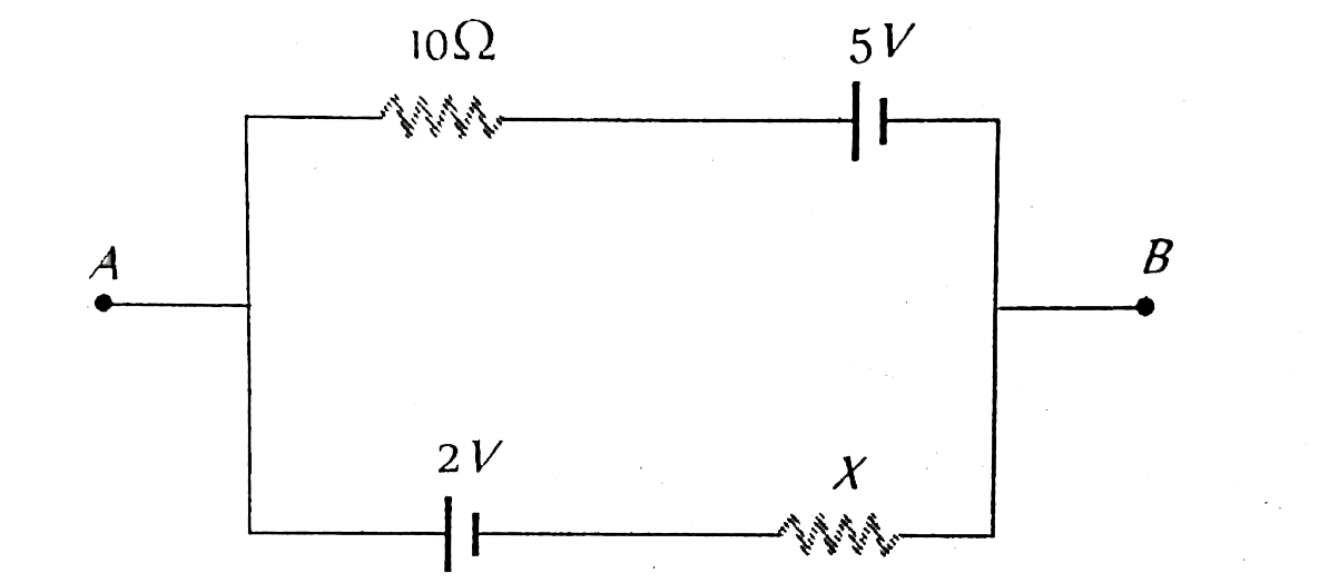
View SolutionIf `V_(AB) = 4V` in the given fig are, then resistance `chi` will be
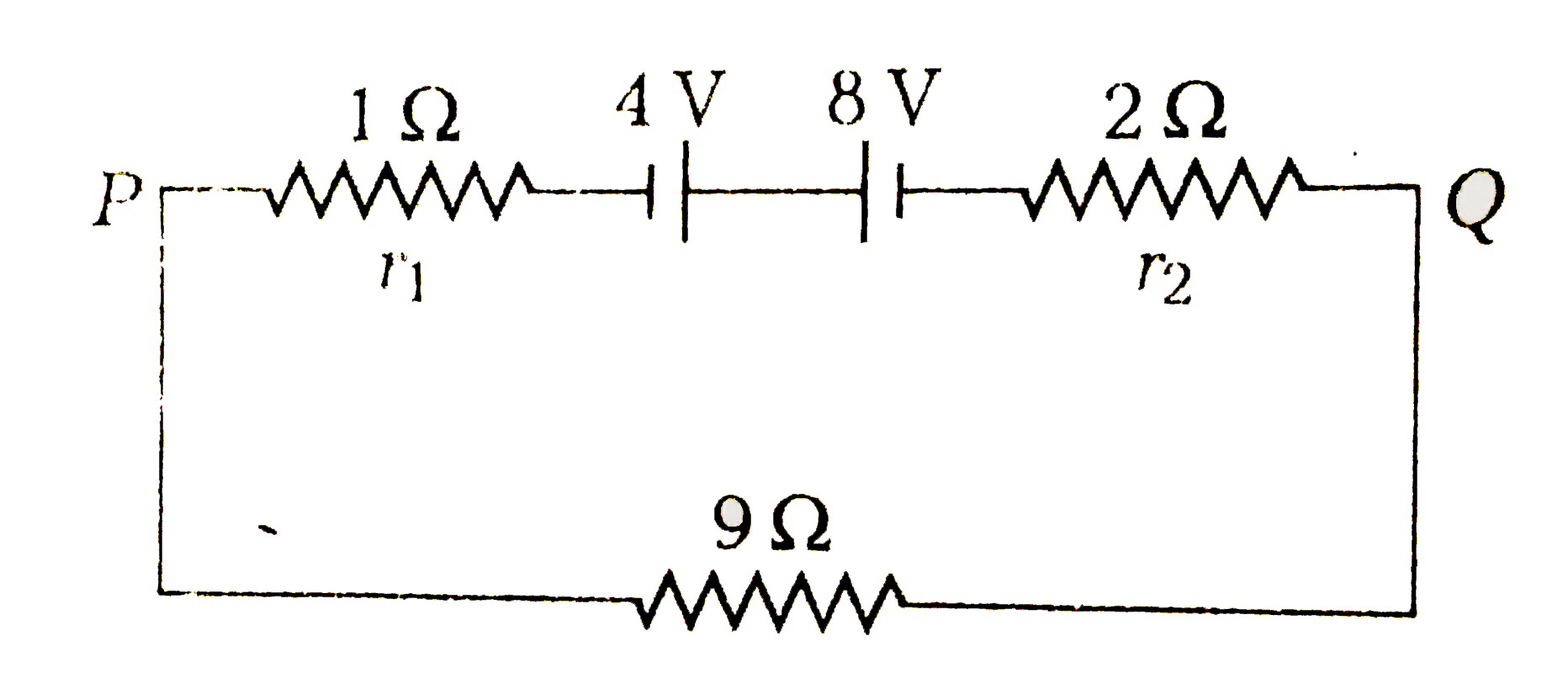
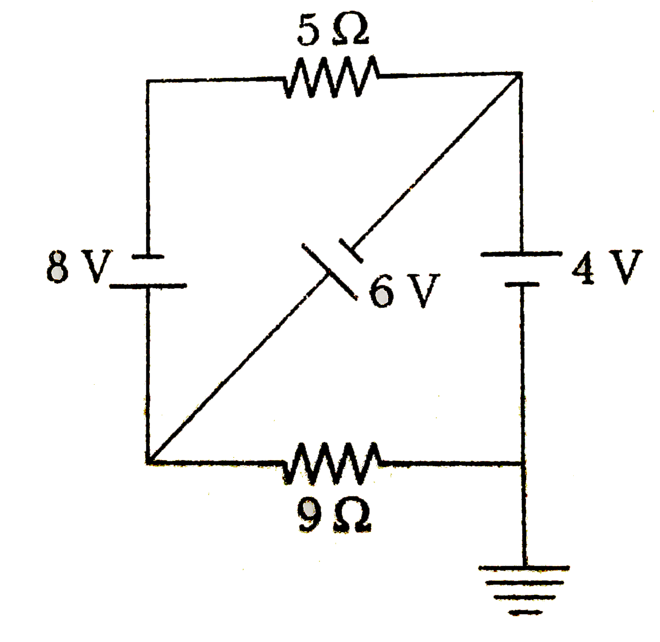
View SolutionTwo batteries of emf 4 V and 8 V with internal resistances `1Omega` and `2Omega` are connected in a circuit with a resistance of `9Omega` as shown in figure. The current and potential difference between the points P and Q are
View SolutionThe current through the `5Omega` resistor is
View SolutionTwo cells , each of `emf E` and internal resistance `r`, are connected in parallel across a resistor `R`. The power delivered to the resistor is maximum if `R` is equal to
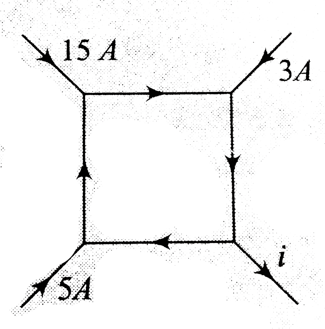
View SolutionShown is a network of currents. The magnitude of the current is also shown there. Find the current `i`.
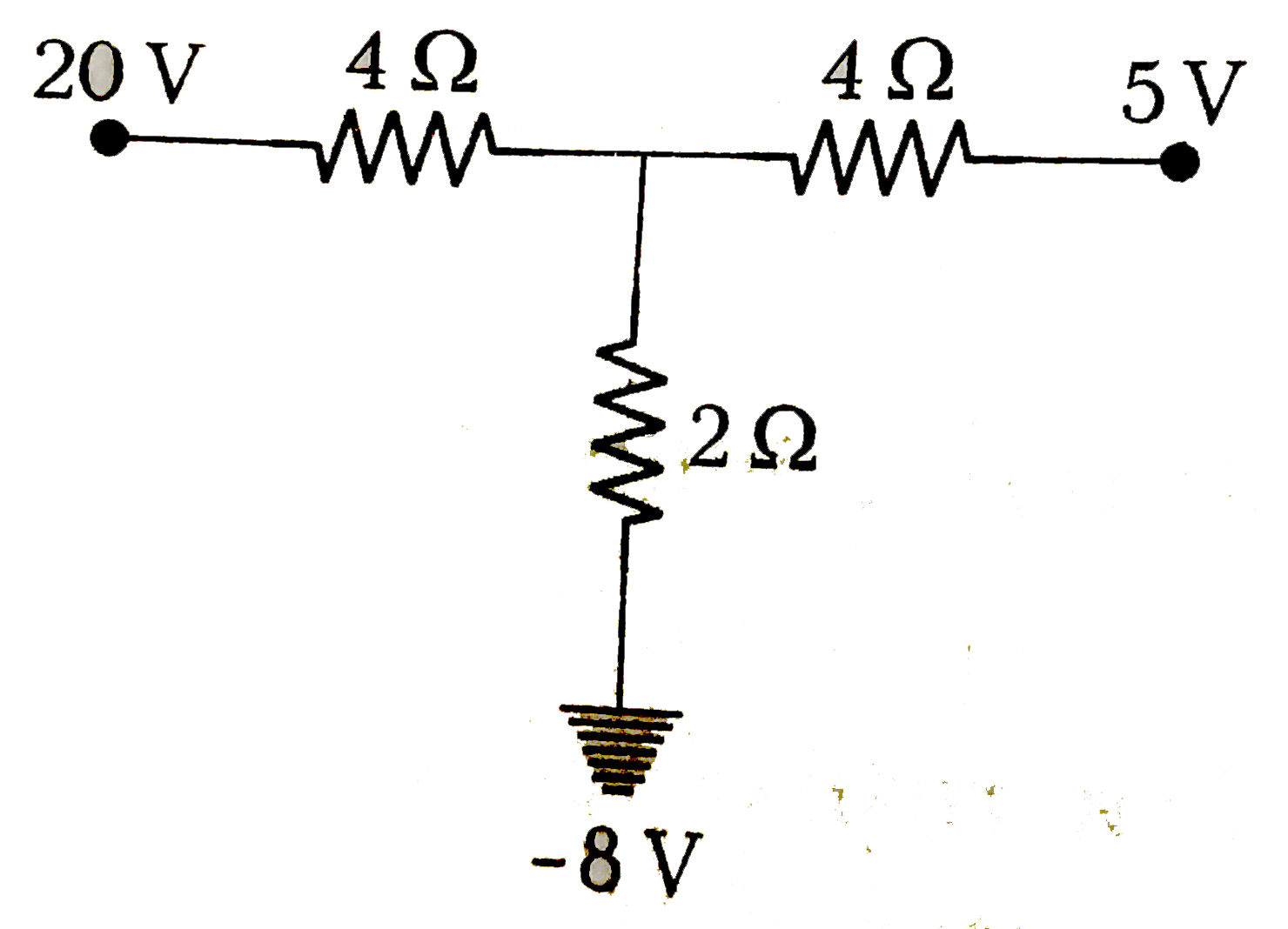
View SolutionIn the circuit element given here, if the potential at point `B = V_(B) = 0`, then the potentials of `A` and `D` are given as

View SolutionThree resistances are connected to form a T-shape as shown in the figure. Then, the current in the `4Omega` resistor is
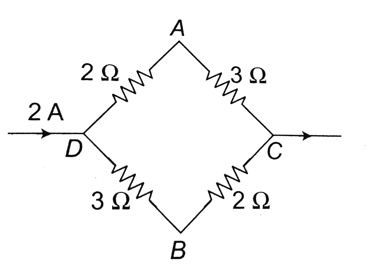
View SolutionA current of `2 A` flows in a system of conductor as shown. The potential difference `(V_(A) - V_(B))`
View SolutionHow much work is required to carry a `6muC` charge from the negative terminal to the positive terminal of a 9 V battery?
View Solutiontwo resistors R and 2R are connected in series in an electric circuit. The thermal energy developed in R and 2R are in the ratio
View SolutionThe resistor of resistance ' R ' is connected to 25 V supply and heat produced in it is 25 J / sec. The value of R is
View SolutionIn India electricity is supplied for domestic use at `220 V`. It is supplied at `110 V` in USA. If the resistance of a `60 W` bulb for use in India is `R`, the resistance of a `60 W` bulb for use in USA will be
View SolutionIf `R_(1)` and `R_(2)` are respectively the filament resistances of a 200 watt bulb and 100 watt bulb designed to operate on the same voltage, then
View SolutionTwo electric bulbs have tungsten filament of same length. If one of them gives `60 W` and the other `100 W` , then
View SolutionA resistor of resistance R is connected to an ideal battery. If the value of R is decreased,the power dissipated in the resistor will
View SolutionHow many calories of heat will be approximately developed in a `210 W` electric bulb in `5 min`?
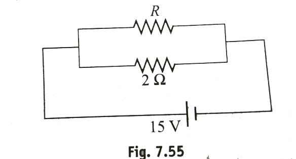
View SolutionIf in the circuit shown in Fig.`7.55`, power dissipation is `150 W` , then find the value of `R ( "in" Omega)`.
View SolutionA wire when connected to `220V` mains sapply power dissipation `P_(1)` Now the wire is cut into two equal pieces which are connected in parallel to the same apply power dissipation in this case is `P_(2)` then `P_(1) : P_(2)` is
View SolutionTwo electric bulbs one, if 200 V-40 W and other 200 V-100 W are connected in series to a 200 V line, then the potential drop across
View SolutionOne kilowatt hour is equal to
View Solution3 identical bulbs are connected in series and these together dissipate a power P . If now the bulbs are connected in parallel, then the power dissipated will be
View SolutionTwo bulbs are working in parallel order. Bulb A is brighter than bulb B . If `R_(A)` and `R_(B)` are their resistance respectively then
View SolutionElectric bulb `50 W - 100 V` glowing at full power are to be used in parallel with battery `120 V`, `10 Omega`. Maximum number of bulbs that can be connected so that they glow in full power is
View SolutionSome electric bulbs are connected in series across a 220 V supply in a room. If one bulb is fused then remaining bulbs are connected again in series across the same supply. The illumination in the room will
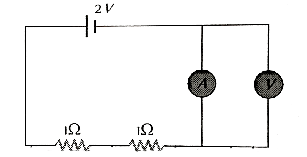
View SolutionIn the circuit shown, A and V are ideal ammeter and voltmeter respectively. Reading of the voltmeter will be
View SolutionThe net resistance of a volmeter should be large to ensure that
View SolutionTwo galvanometers A and B require 3 mA and 6 mA respectively, to produce the same deflection of 10 divisions. Then,
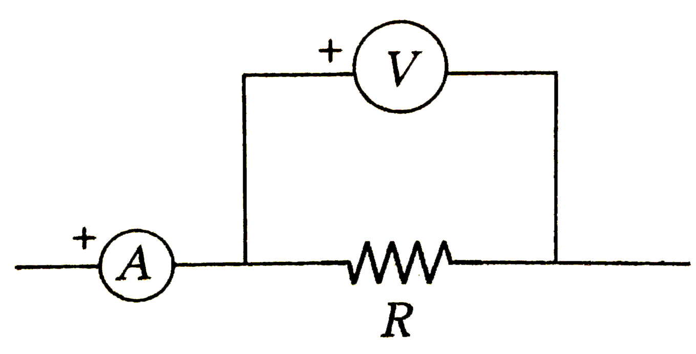
View SolutionAn ammeter A, a voltmeter V and a resistance R are connected as shown in the figure. If the voltmeter reading is `1.6V` and the ammeter reading is `0.4`A, then R is
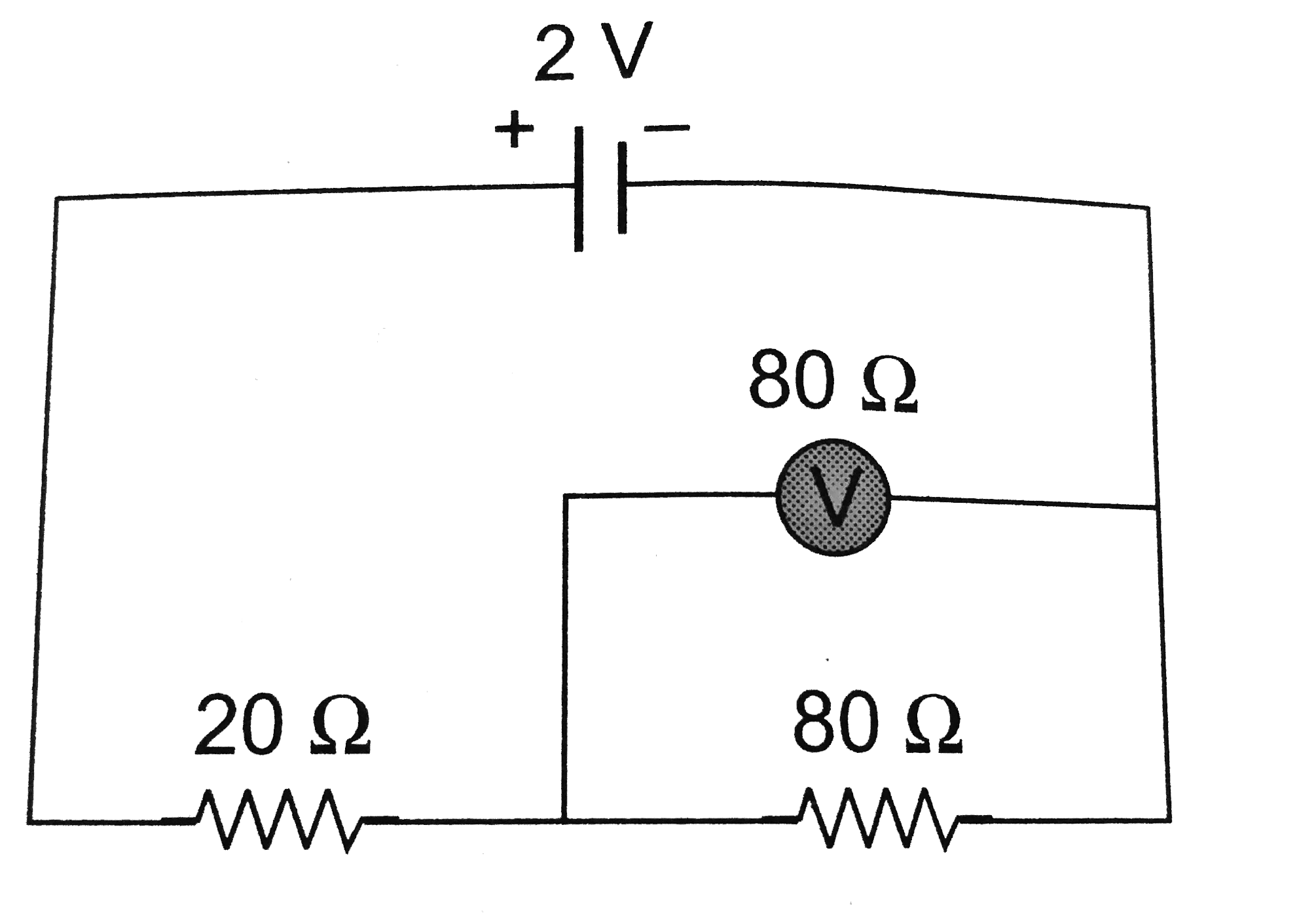
View SolutionIn the adjoining circuit, the e.m.f. of the cell is 2 volt and the internal resistance is negligible. The resistance of the voltmeter is `80 ohm`. The reading of the voltmeter will be
View SolutionWhat is the reading of voltmeter in the following figure ?
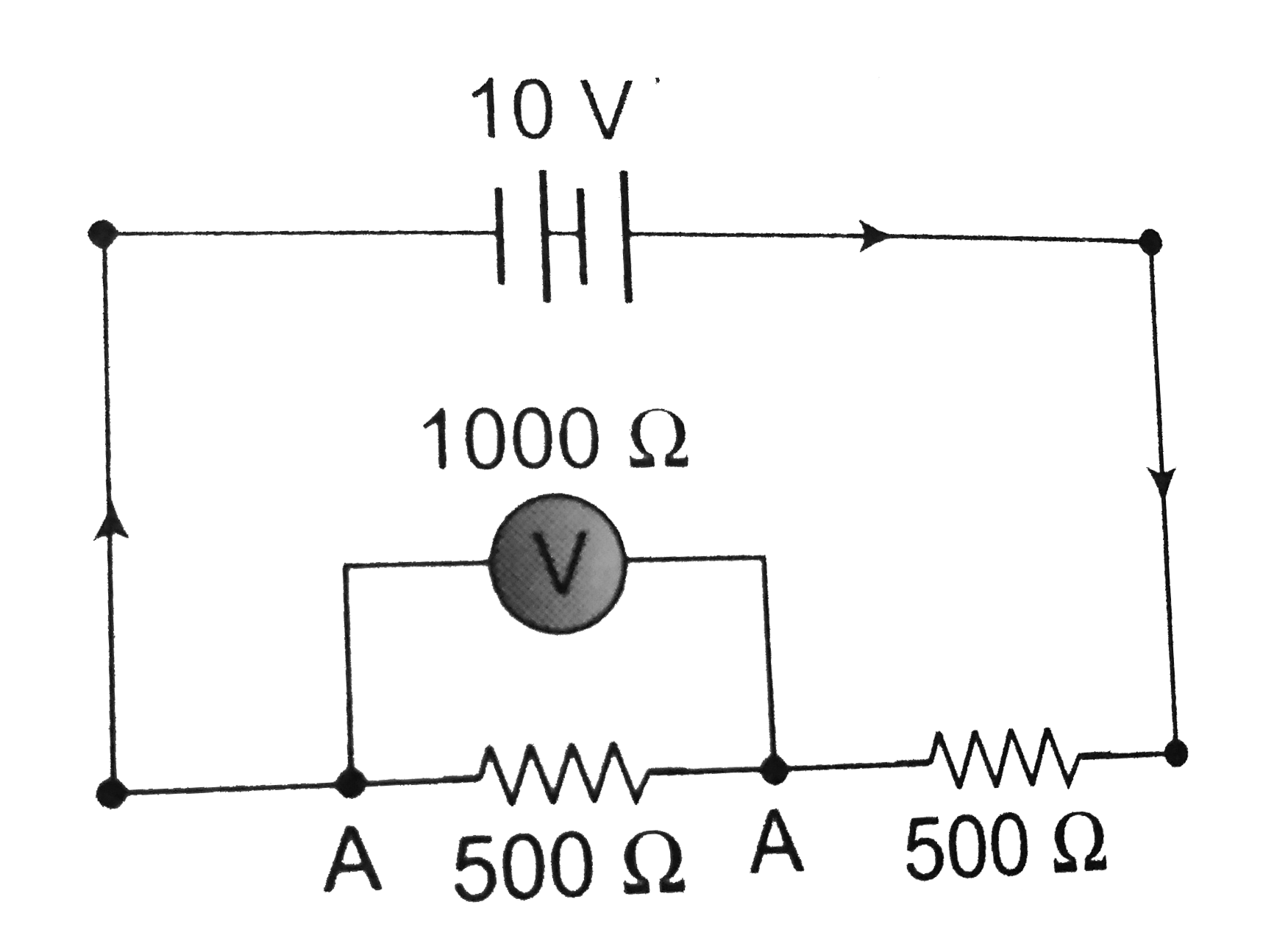
View SolutionA galvanometer of resistance `25 Omega` gives full scale deflection for a current of 10 milliampere , is to be changed into a voltmeter of range 100 V by connecting a resistance of ‘ R ’ in series with galvanometer. The value of resistance R in `Omega` is
View SolutionAn ammeter and a voltmeter are joined in sereis to a cell. Their readings are `A` and `V` respectively. If a resistance is now joinding parallel with the voltmeter. Then
View SolutionIn the circuit shown in the figure, the voltmeter reading is
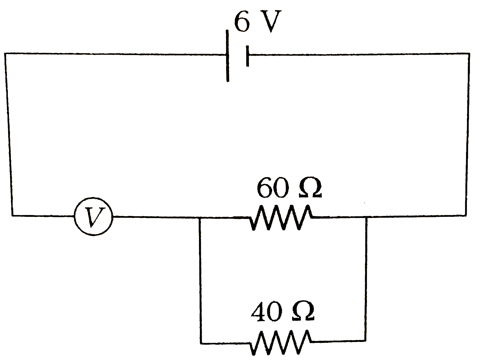
View SolutionThe shunt required for 10% of main current to be sent through the moving coil galvanometer of resistance `99 Omega` will be-
View SolutionThe potential difference across the `100 Omega` resistance in the following circuit is measured by a voltmeter of `900 Omega` resistance. The percentage error made in reading the potential difference is
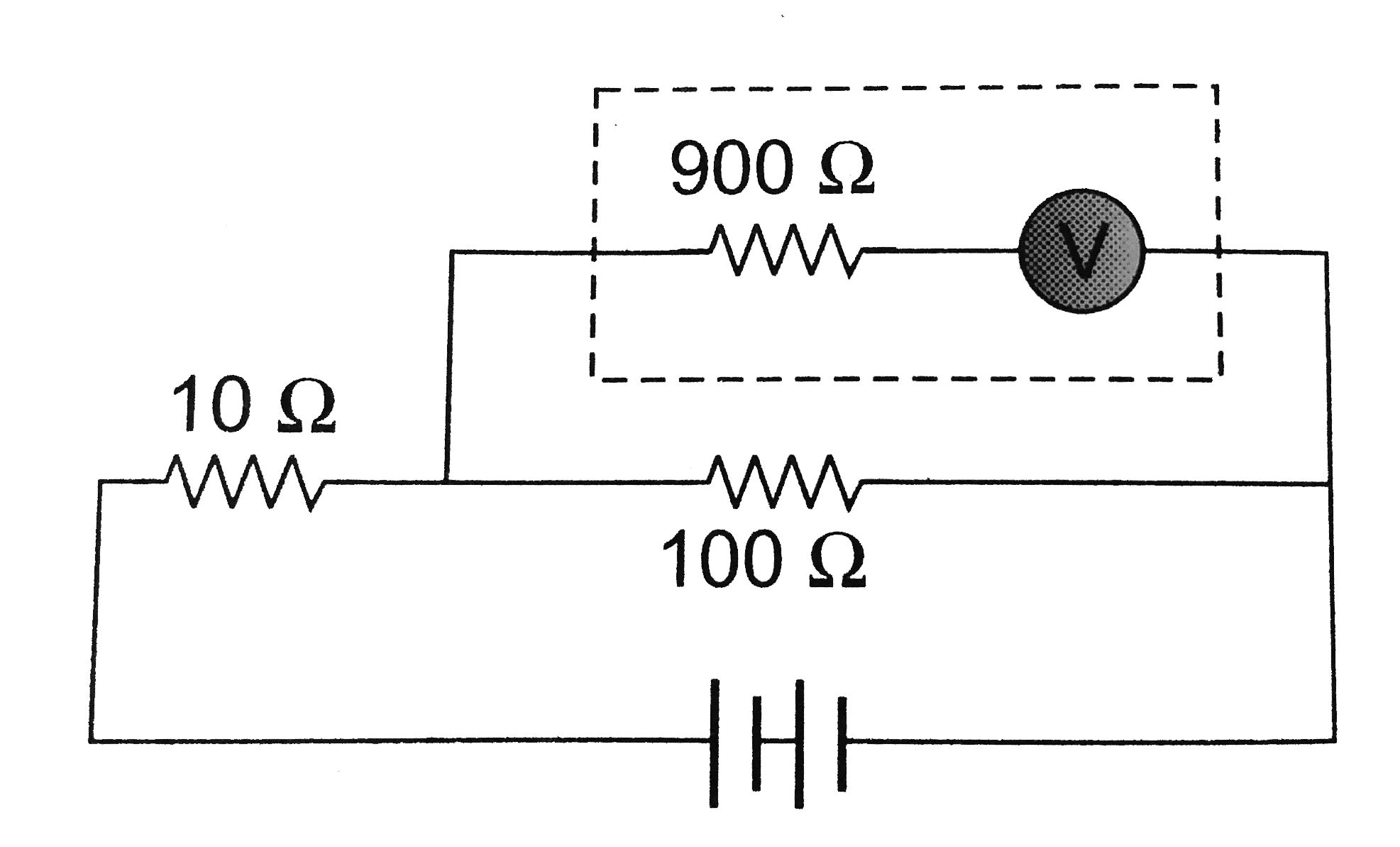
View SolutionA microammeter has as resistance of `100 Omega` and full scale range of `50 muA`. It can be used as voltmeter or as a higher range ammeter provided a resistance is added to it. Pick the correct range and resistance combinations
View SolutionShow that the percentage error in the measurement of resistance by a metre bridge is minimum when the null point is near about the centre of the wire.
View SolutionA resistance of `1980Omega` is connected in series with a voltmeter, after which the scale division becomes 100 times larger. Find the resistance of voltmeter.
View SolutionIn the given circuit, it is observed that the current I is independent of the value of the resistance `R_6`. Then the resistance values must satisfy
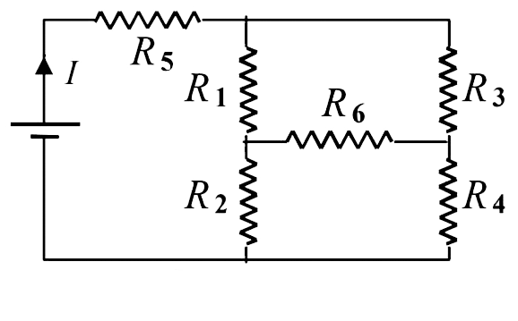 .
.
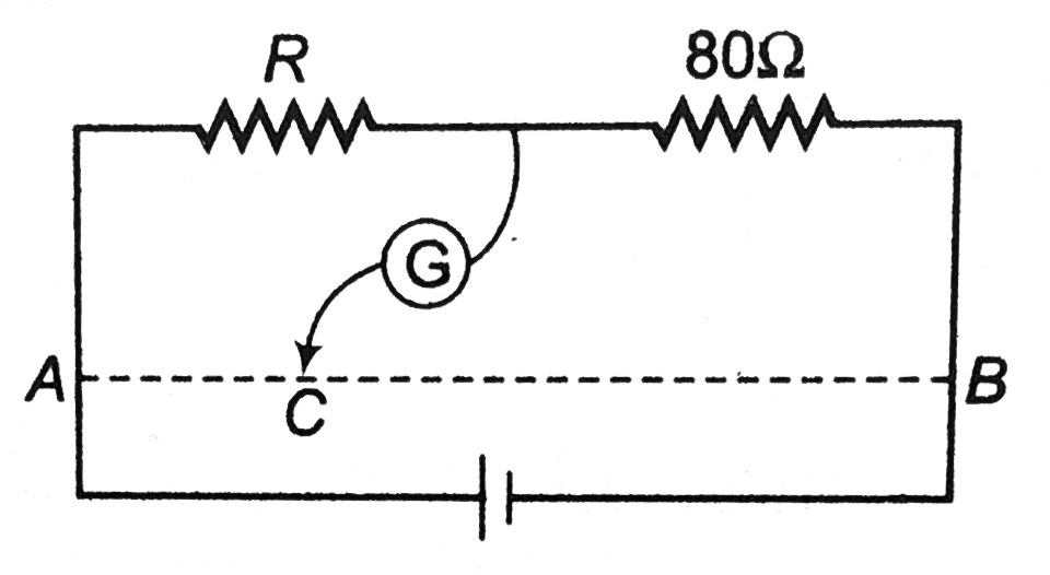
View Solution`AB` is a wire of uniform resistance. The galvanometer `G` shows no deflection when the length `AC = 20 cm` and `CB = 80 cm`. The resistance `R` is equal to.
 .
.
View SolutionA potentiometer is used for the compaisem of e.m.f. of two cells `E_(1)` and `E_(2)`. For cell `E_(1)` the no deflection point os obtained at `20 cm` and for `E_(2)` the no deflection point is obtained at `30 cm`. The ratio of their e.m.f.'s will be
View SolutionIn a potentiometer experiment, the galvanometer shows no deflection when a cell is connected across `60 cm` of the potentiometer wire. If the cell is shunted by a resistance of `6 Omega`, the balance is obtained across `50 cm` of the wire. The internal resistance of the cell is
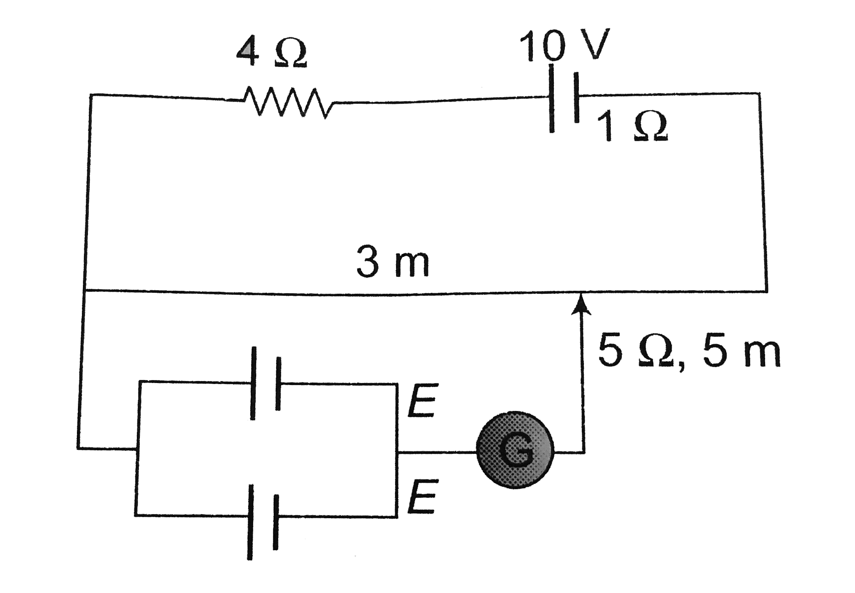
View SolutionA resistance of `4 Omega` and a wire of length 5 meters and resistance `5 Omega` are joined in series and connected to a cell of e.m.f. `10 V` and internal resistance `1 Omega`. A parallel combination of two identical cells is balanced across `300 cm` of wire. The e.m.f. `E` of each cell is
View SolutionPotentiometer wire of length `1 m` is connected in series with `490 Omega` resistance and `2 V` battery. If `0.2 mV/cm` is the potential gradient, then resistance of the potentiameter wire is approximately
View Solution
Check point questions and complete solutions for chapter CURRENT ELECTRICITY of DC PANDEY ENGLISH of Class 12
All Exercises from DC PANDEY NEET Class 12 PHYSICS CURRENT ELECTRICITY
- B. Assertion and reason
- Check point
- Example
- Example Example Type
- Example Type 1
- Example Type 2
- Example Type 3
- Example Type 4
- Example Type 5
- Example Type 6
- Exercise 23.1
- Exercise 23.10
- Exercise 23.11
- Exercise 23.12
- Exercise 23.13
- Exercise 23.2
- Exercise 23.3
- Exercise 23.4
- Exercise 23.5
- Exercise 23.6
- Exercise 23.7
- Exercise 23.8
- Exercise 23.9
- Level 1 Assertion And Reason
- Level 1 Objective
- Level 1 Subjective
- Level 2 Comprehension Example Type
- Level 2 More Than One Correct
- Level 2 Single Correct
- Level 2 Subjective
- Match the columns
- Medical entrances gallery
- Miscellaneous Examples
- OBJECTIVE_TYPE
- Taking it together