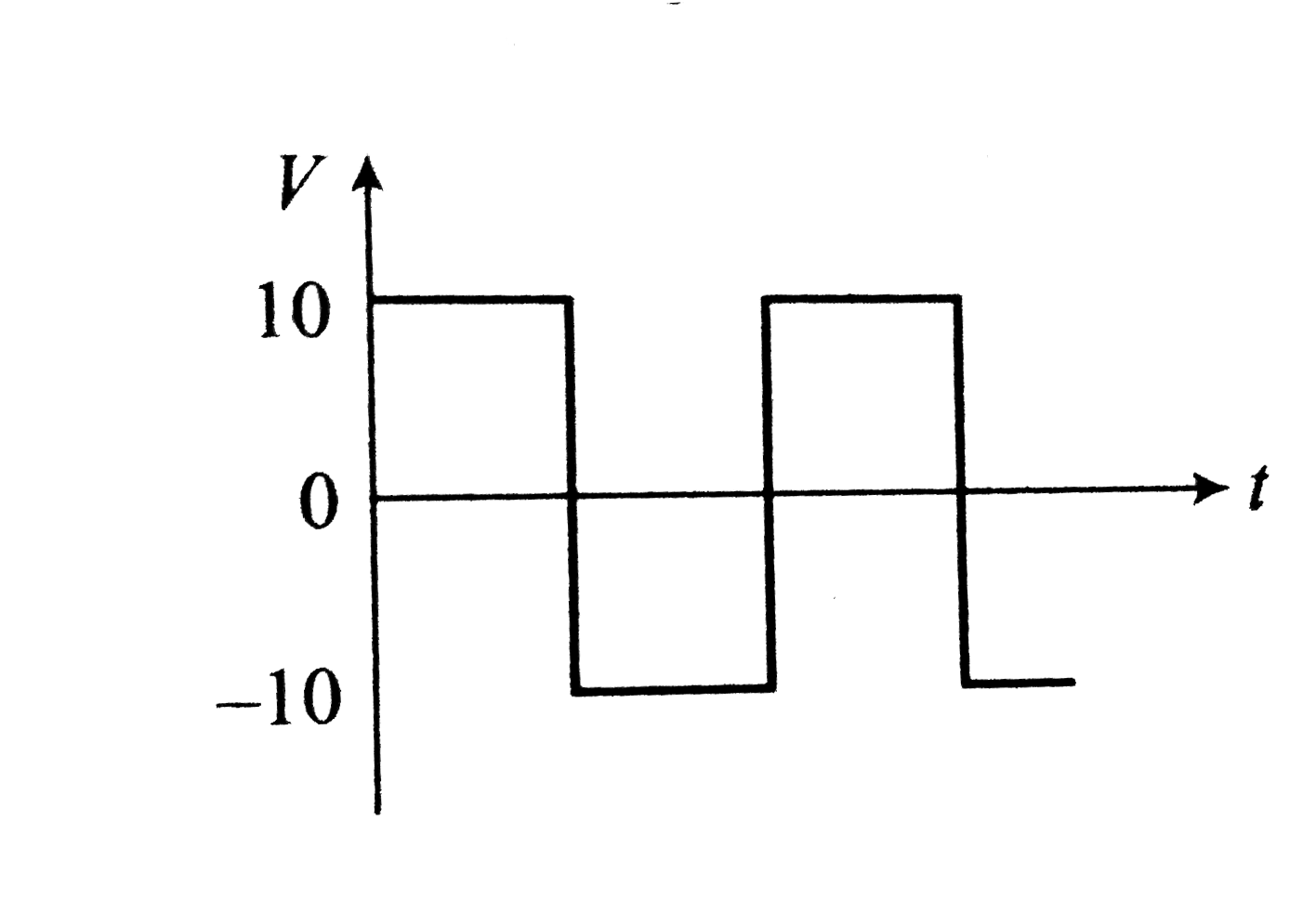
The rms voltage of the wave form shown is
10V
7V
6.37V
none of these
The correct Answer is:A
Step by step video & image solution for The rms voltage of the wave form shown is by Physics experts to help you in doubts & scoring excellent marks in Class 12 exams.
Updated on:21/07/2023Topper's Solved these Questions
- ALTERNATING CURRENTBOOK - CENGAGE PHYSICS ENGLISHCHAPTER - ALTERNATING CURRENTEXERCISE - Comphension Based
8 Videos
- ALTERNATING CURRENTBOOK - CENGAGE PHYSICS ENGLISHCHAPTER - ALTERNATING CURRENTEXERCISE - Single Correct
10 Videos
- ALTERNATING CURRENTBOOK - CENGAGE PHYSICS ENGLISHCHAPTER - ALTERNATING CURRENTEXERCISE - Archives Integer
1 Videos
- ATOMIC PHYSICSBOOK - CENGAGE PHYSICS ENGLISHCHAPTER - ATOMIC PHYSICSEXERCISE - ddp.4.3
15 Videos
Similar Questions
The r.m.s. voltage of the wave form shown is
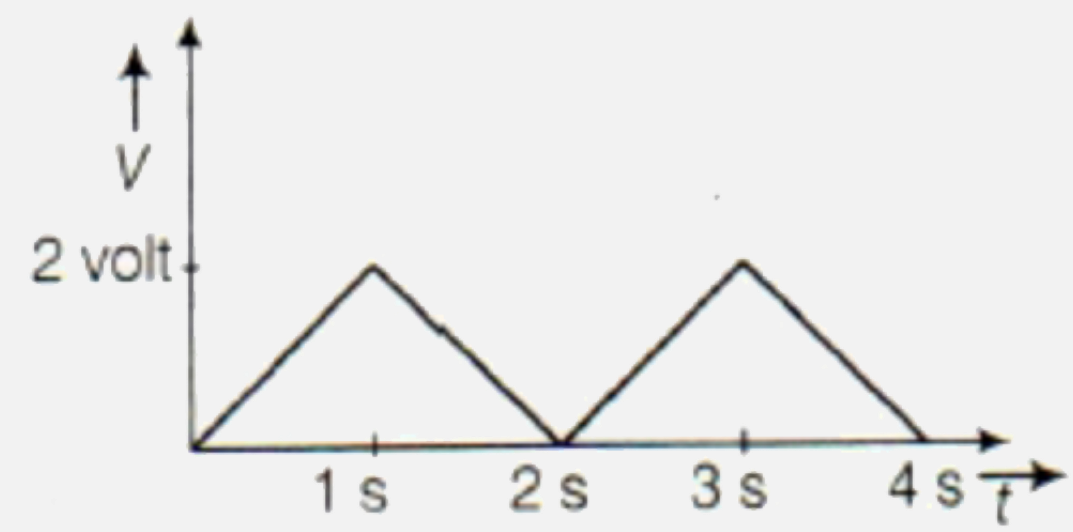
View SolutionIf the rms value of the voltage of the waveform shown below is √pqV , then what is the value of (p+q) ? (p and q are the smallest positive integers.)
View Solution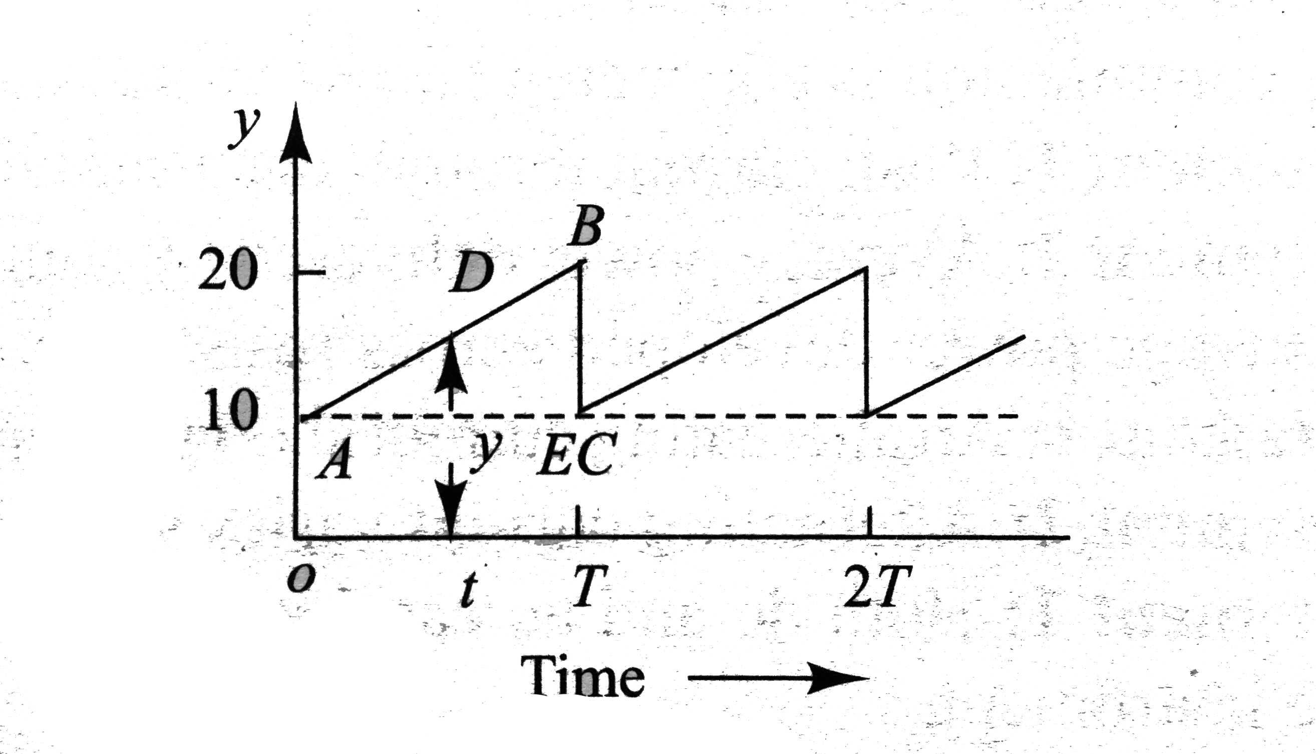
the average value of the wave-from shown in fig. is
View SolutionAn ac source of 50 V (r.m.s value) is connected across a series R - C circuit. If the r.m.s voltage across the resistor is 40 V, then the r.m.s voltage across the capacitor is
View SolutionFind the rms and the average values of the saw tooth waveform shown in fig.
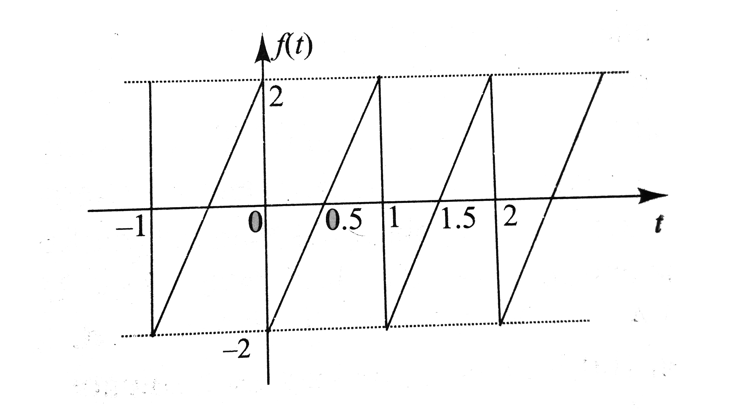 .
.
View SolutionIn the series L−C−R circuit shown in the figure, the rms voltage across the resistor and inductor are 400 V and 700 V respectively. If the applied voltage is E=500√2sin(ωt), then the peak voltage across the capacitor is
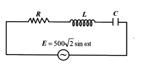
View SolutionIn a series LCR circuit the rms voltage across the inductance , capacitance and resistance are respectively 4 V, 8 V and 5 V . The RMS voltage of the AC source in the circuit is
View SolutionIn a series RLC circuit the r.m.s. voltage across the resistor and the inductor are respectively 400 V and 700 V. If the equation for the applied Voltage is ε=500√2sinωt. then the peak voltage across the capacitor is
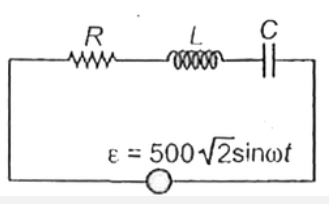
View SolutionThe figure shows a logic circuit with two inputs A and B and the output C. The voltage wave forms across A,B and C are as given. The logic circuit gate is
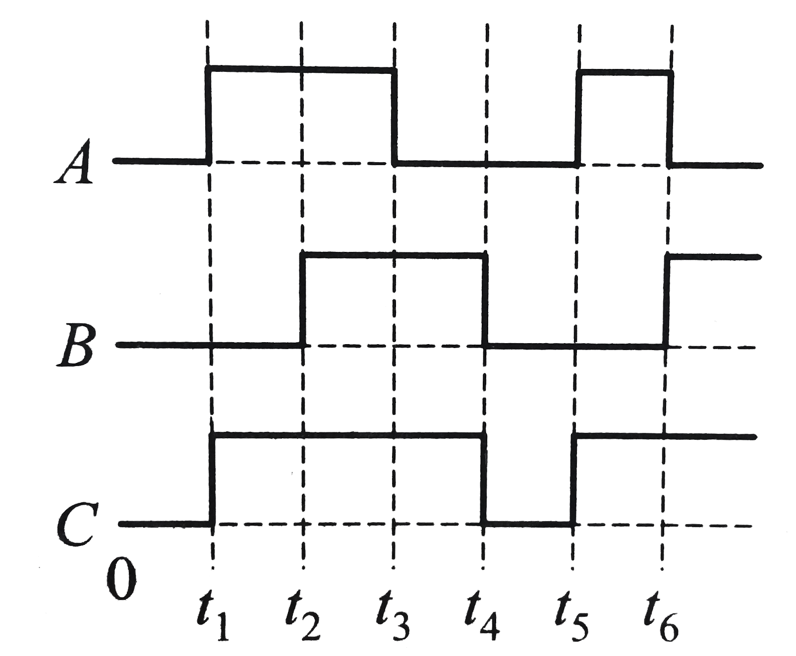
View SolutionA coil of resistance R and inductance L is connected across an a.c power supply of r.m.s. voltage V. The average power dissipated in the coil is,
View Solution
