Complete Solutions to EXAMPLE of chapter CURRENT ELECTRICITY of Class 12 book with complete answers and questions
| Class 12 | PHYSICS |
| Chapter | CURRENT ELECTRICITY |
| AAKASH INSTITUTE | EXAMPLE |
| Number Of Questions | 77 |
| Academic Year | 2023-24 |
`10^(6)` positrons are flowing normally through an area in forward direction and same amount of electrons are flowing in backward direction in the interval of 10 ms.Find the current through the area.
View SolutionCharge through a cross-section of a conductor is given by `Q = ( 2t^(2) + 5t) C `. Find the current through the conductor at the instant `t = 2 s `.
View SolutionWhat do you mean by thermal motion of free electrons in conductors ?
View SolutionCan electrons produce current due to their thermal speed . Explain.
View SolutionResistance of a conductor of length l and area of cross-section A is R. If its length is doubled and area of cross-section is halved, then find its new resistance.
View SolutionIf `vec(j)` and `vec(E )` are current and electric field inside a current carrying conductor at an instant then `vec(j). Vec( E )` is
(1) Positive (2) Negative
(3) Zero (4) May be positive or negative
View SolutionFind the average drift speed of free electrons in a copper wire of area of cross-section `10^(-7) m^(2)` carrying current of 1.5 A and having free electron density `8.5 xx 10^(28) m^(-3)`
View SolutionWhat are the possible paths of free electrons inside the conductor ?
View SolutionFind the resistance of following carbon resistor .

View SolutionResistance of platinum wire in a platinum resistance thermometer at melting ice, boiling water and at a hot bath are `5 Omega , 5.5 Omega` and `5.2 Omega ` respectively . Find temperature of hot bath.
View SolutionCurrent 2 A is flowing through a conductor fo resistance 4 `Omega` . Find the electrical energy consumedin 10 s.
View SolutionTwo resistance 12 `Omega ` and `4 Omega ` are supplied to you . Find the maximum and minimum resistance that can be achieved by using form .
View Solution
Find the resistance across AB.
View SolutionA cell of emf 10V and internal resistance `5 Omega` is connected across a resistance `15 Omega `. Find potential difference across AB.

View Solution
In the network shown in the above figure, find the current through 3` Omega ` and `10 Omega ` resistances.
View SolutionWhen a dry a cell is connected acrossa bulb and the circuit is switched on , then the brightness of bulb goes on decreasing . Explain.
View SolutionWhat is the relationship between potential difference across the terminalsof a cell and emf of the cell?
View SolutionA cell of emf `epsilon` and internal resistance r is connected across a load resistance R
(i) Find the maximum power delivered at the load ?
.
View SolutionA cell develops the same power across two resistances `R_(1)` and `R_(2)` separately. The internal resistance of the cell is
View SolutionFind the current l through then `10 Omega ` resistance in the network shown in figure.
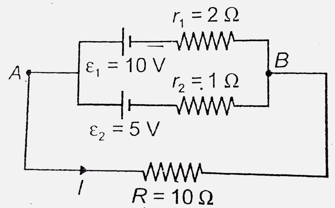
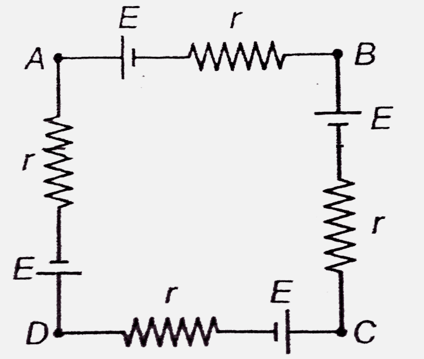
View SolutionFour cells each of emf E and internal resistance r are connected in series to form a loop ABCD. Find potential difference across (1) AB, (2) AC
View SolutionTwo cells of emf E each and internal resistance `r_(1)` and `r_(2)` are connected in series across a load resistance R. If potential difference across the first cell is zero, then find the relation between `R, r_(1)` and `r_(2)`
View SolutionIn the network in given find `l_(1), l_(2)` and l.

View Solution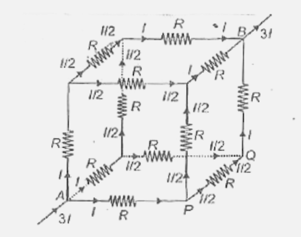
Twelve indentical resistance each of resistance R are joined to form a cube as shown in figure. Find resistance of the combination across AB.
View SolutionIn the network shown in given figure, find the potential difference across BD
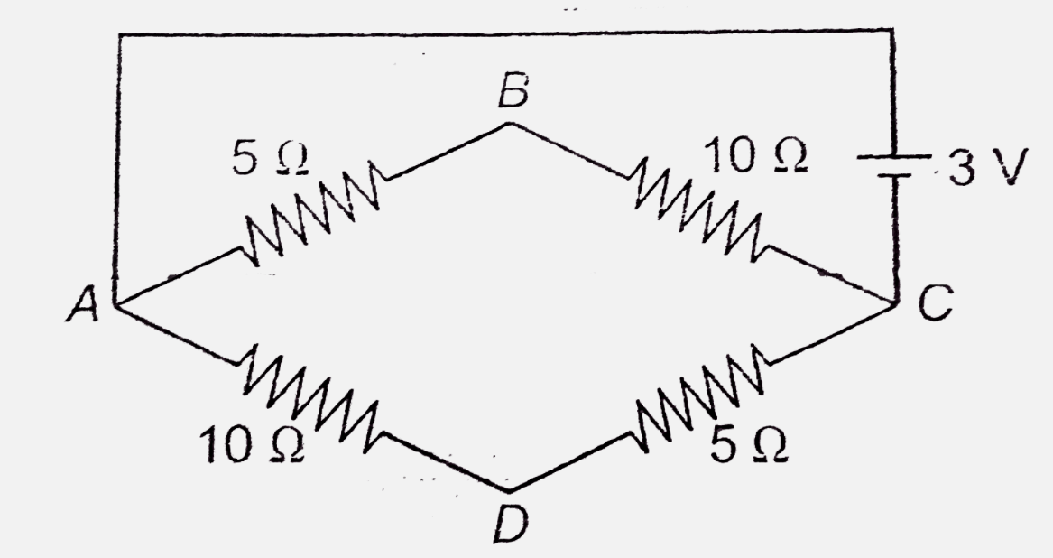
View SolutionIn the network shown in given figure the current `l_(1) ` through the 10 V battery .
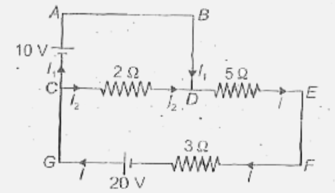
View Solution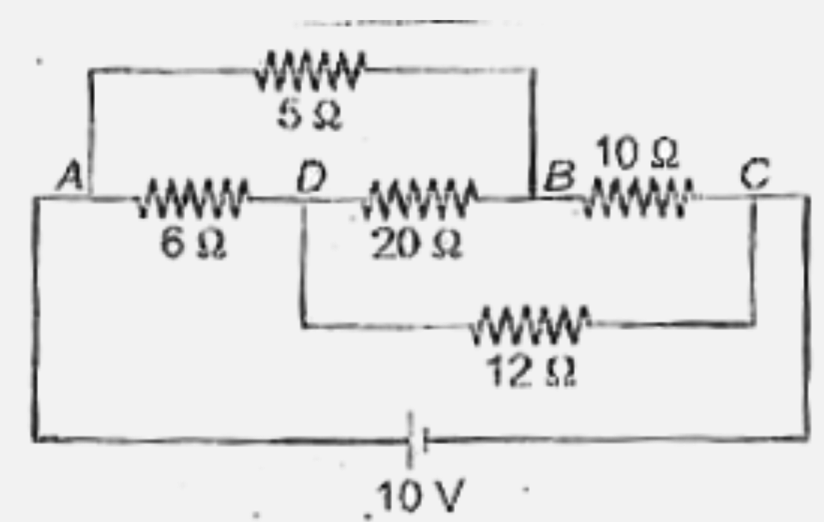
In the above network , find the current through the `20 Omega` resistance and current through the battery .
View SolutionThe equivalent resistance across AB in the given network is
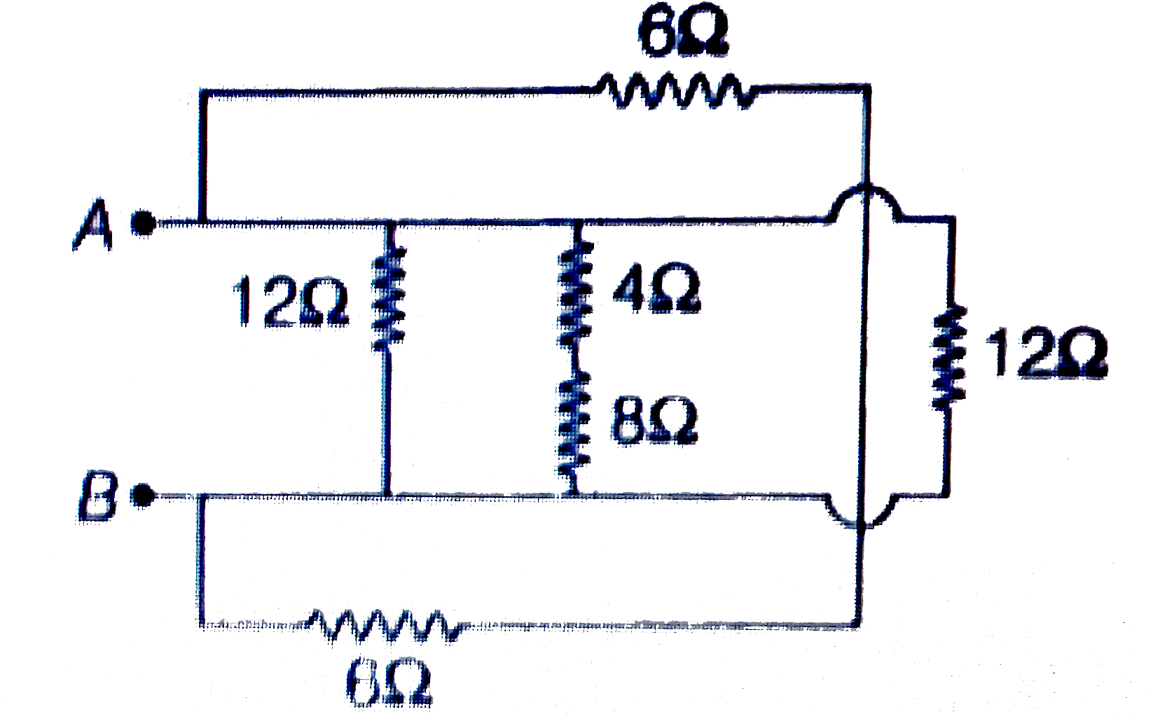
View Solution
In ther meter bridge circuit shown in figure. Find the length AB for null deflection in galvanometer.
View SolutionIn a potentiometer arrangement a cell of emf 1.5 V gives a balance point at 30 cm length of wire. Now, when the cell is replaced by another celle , the balance point shifts to 50 cm. What is the emf of second cell ?
View Solution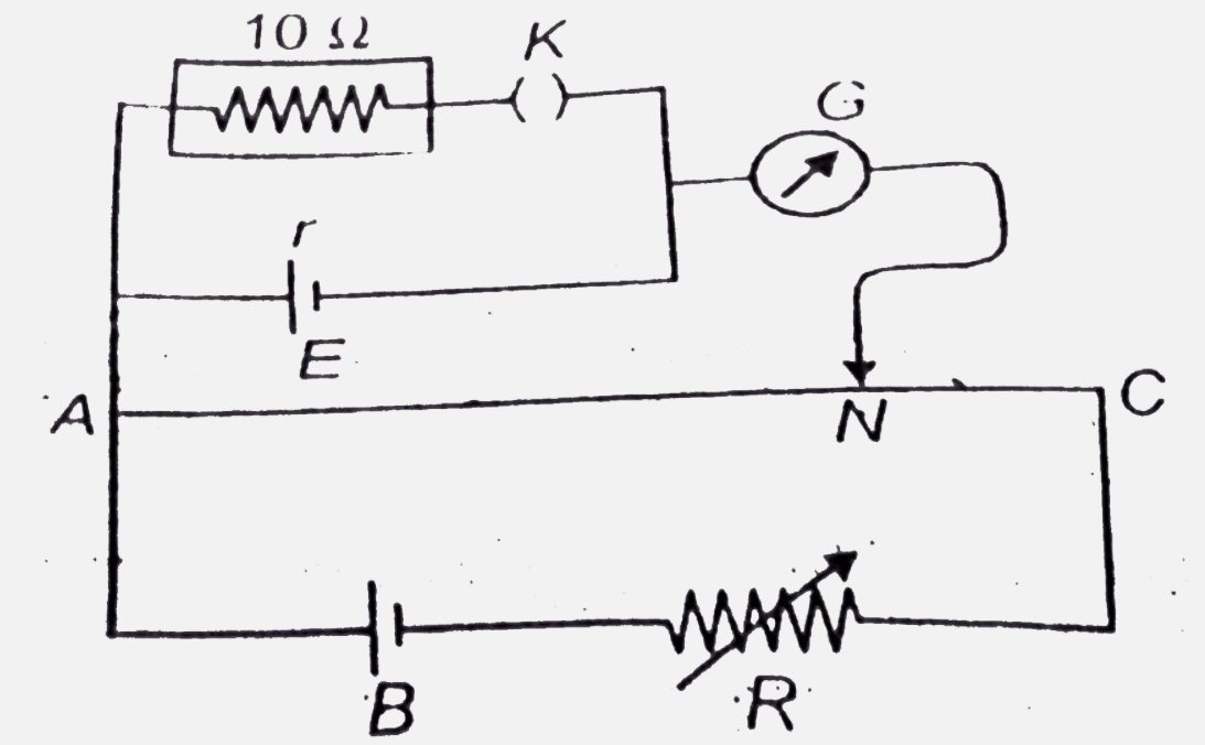
In the given potentiometer circuit internal resistance r of the cell of emf `epsilon` is to be determined when K is open balance point is obtained at `N_(1) , AN_(1) = 60 cm`. When K is close balance point is obtained at `N_(2) , AN_(2) = 50 cm ` , what is the value of r ?
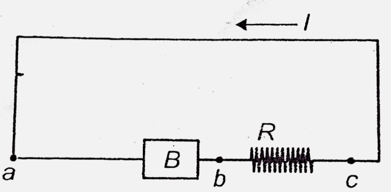
View SolutionFigure shows a battery B having emf resistor having resistance R in a closed circuit.
(1) Show arrow for emf E of the battery B.
(2) Arrange points a,b,c in decreasing order of magnitude of current
(3) Arrange points a,b,c in decreasing order of electric potential .
(4) Arrane points a,b. In increasing order of electric potential energy of charge carriers.
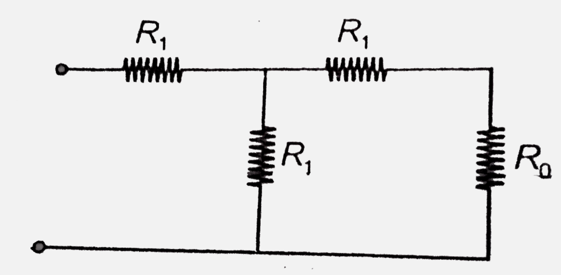
View SolutionConsider the circuit shown in figure . For a given resistance `R_(0)` what must be the value of `R_(1)` so that the equivalent resistance between the terminals is equal to `R_(0)` ?
View SolutionThe figure shows an infinite circuit formed by the repetiton of the same link , consisting of resistance `R_(1) = 4.0 Omega ` and `R_(2) = 3.0 Omega ` . Find the resisance of this circuit between points A and B.
View SolutionFigure (A) and (B) show two resistors with resistances `R_(1)` and `R_(2)` connected in parallel and in series. The battery has a terminal voltage of e.

Suppose `R_(1)` and `R_(2)` are connected in parallel .
(a) Find the power delivered to each resistor.
(b) Show that the power used by each resistor is equal to the power supplied by the battery .
Suppose `R_(1)` and `R_(2)` are now connected in series
(c ) Find teh power delivered to each resistor.
(d) Show that the sum of the power by each resistor is equal to the power supplied by the battery.
(e ) Which configuration , parallelor series, uses more power ?
View SolutionAn electric kettle used for heating water has two heating elements. One raises the temperature of water by `Delta theta` in time `t_(1)` and another in time `t_(2)`. Assuming no loss of heat , find the time taken to raise the temperature by `Delta theta`.
(i) When heating elements are connected in series.
(ii) When heating elements are connected in parallel.
View SolutionIn an experiment to measure the membrane potential of a living plant cell micro-electrodes are placed inside and outside the cell. The membrane potential is measured to be 120 mV and a current of 1.5 nA flows through the membrane .Assume that the current density in the cell is uniform.
The total area of the cell membrane is `2.0 m m^(2)` and its thickness is 12 `mum `.
(a) What is the current density in the membrane?
(b) What is the resistivity of the membrane ?
View SolutionThe following table gives the current l ( in amperes) through two devies for several values of potential differences V( in volt ) . From these data which does not obey ohm's law ?
View SolutionTwo 100W bulbs one having the tungsten filament and the other carbon filament are joined in series with a power supply. How will their brightness change as time passes on .
View SolutionResistance thermometer . The variation in electrical resistance with temperature can be used to make precise temperature measurements. Platinum is commonly used since it is relatively free from corrosive effects and has a high melting point. Suppose at `20.0 ^(@)C` the resistance of a platnum resistance thermometer is `164.2 Omega ` When praised in a particular solution, the resistance is`187.4 Omega ` . What is the temperature of this solution ?
View SolutionA current is flowing through a cylinderical conductor of radius R, such that current density at any cross-section is given by `J = J_(0)(1-(r )/(R ))`, where r is radial distance from axis of the cylinder .Calculate the total current through the cross-section of the conductor.
View SolutionA chrged spherical conductor a radius and charge q, is surrounded another charged concentric spehere of `b(bgta)`. The potential difference between conductors is V. When, the spherical conductor of radius b is discharged completely then the potential between conductor will be
View SolutionTwo metal balls of the same radius `a` are located in a homongenous poorly conducting medium with resistivity `rho`. Find the resistance of the medium between the balls provided that the separation between them is mush greater than the radius of the ball.
View SolutionConsider a hollow cylinder of length L and inner radius a and outer radius b, as shown in figure. The material has resistivity `rho`.
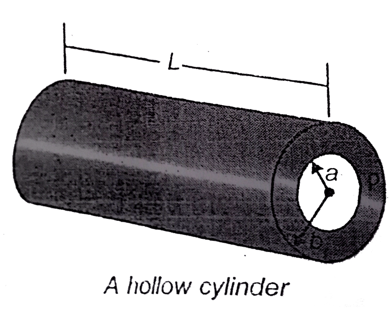
(a) Suppose a potential difference is applied between te ends of the cylinder and produces a current parallel to the axis. What is the resistance measure ?
(b) If instead the potential difference is applied between the inner outer surfaces so that current flows radially outward, what is the resistance measure ?
View SolutionWhen a celll is connected to an external resistance `R_(1)`, current through it is `i_(1)`. When the same cell is connected to an external resistance `R_(2)`, current through it is `i_(2)`. Calculate the emf and internal resisance of the cell.
View SolutionIn the circuit shown, find the terminal potential difference across each cell. Also,if `epsilon_(1)= epsilon_(2)`, find the condition that terminal potential difference across the cell of emf `epsilon_(1)` is zero .

View SolutionFigure shows 3n cells connected in series to form a circuit r is the internal resistance of each cell and e is th eemf of each cell. If polarity of n cells are reversed , find the terminal voltage across cell A.

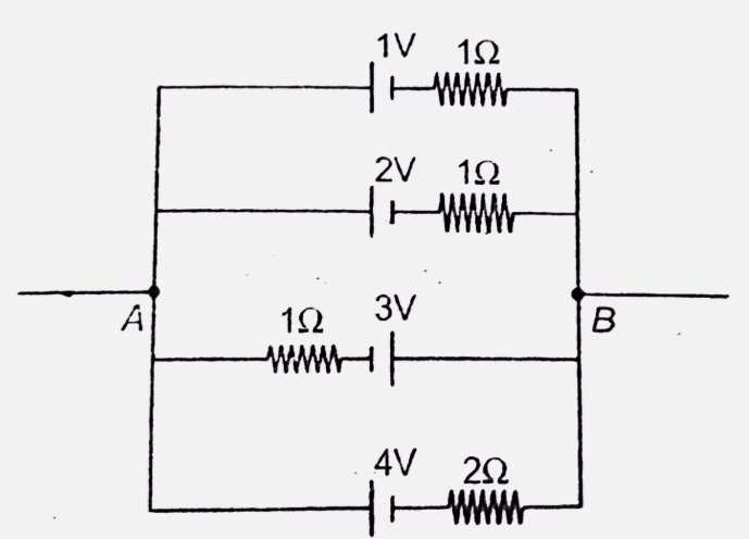
View SolutionFind equivalent emf of four different cells which are connected in parallel. Their emf's and internal resistance are 1 volt, `1 Omega , 2` volt, `1 Omega,3` volt, `1Omega,4` volt, `2 Omega` and their connection is given below .
View SolutionIn the circuit shown , find the current through the battery when switch S is (i) open (ii) closed.

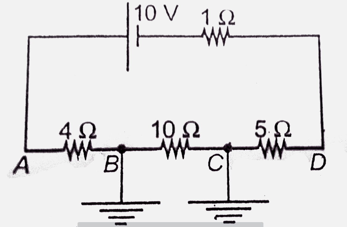
View SolutionIn the electrical circuit shown, points B and C are earthed . Find the potentials of points A and D .
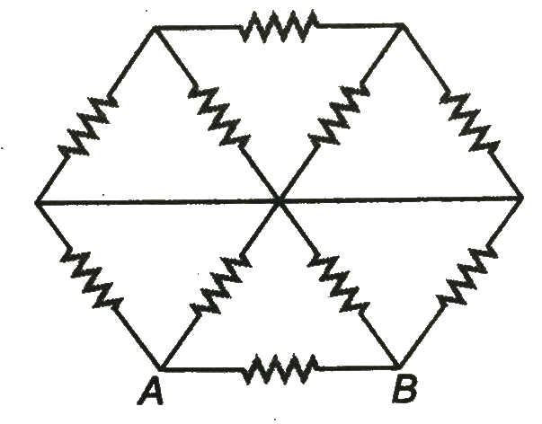
View SolutionFind equivalent resistance between A and B

View SolutionIn the network shown, each resistance is R. Calculate the equivalent resistance between A and B.
View SolutionFind the effective resistance between A and l if `r= 2 Omega `
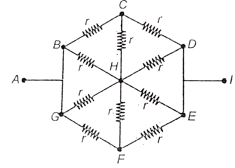
Strategy `:` (1) Remove CH and HF since they are at the same potential of symmetric network.
(2) Find the equivalent resistance between A and l.
View SolutionFive equal resistance each of value R are connected in a circuit . Find equivalent resistance of the network between points A and C
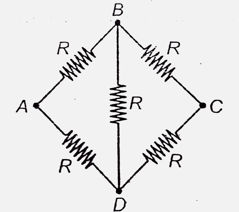
View SolutionRefer to the figure , find equivalent resistance between points B and D.
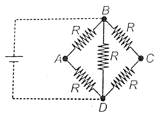
View SolutionFind the equivalent resistance between A and B

Strategy `:` Step- 1 `:` Convert the triangles of resistance between the points AC,CB,BD,DA
Step -2 `:` Simplify the circuit in the form of a bridge of four arms.
Step-3 `:` Check whether bridge is balanced or not.
View SolutionIn the given square each side is of 1m and resistance of wire is `1 Omega // m` and resistance between AE is `1 Omega `. A constant potential difference is applied across A and C. If potentials of B and E are same, then

(a) `(CE)/(E D) = (1)/(sqrt(2))` (b) `(CE)/(ED)=1`
(c ) `(CE)/(ED)=2` (d) `(CE)/(ED)=sqrt(2)`
Strategy `:` The potential of points B and E will be same , when this is a balanced bridge circuit.
View SolutionFind the equivalent resistance of the network shown in figure between points A and B.
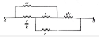
where k is a positive constant.
View SolutionFind the equivalent resistance between P and Q of the given network.

Strategy `:` (1) Remove the resistance between 1,2 and 2,3 since it is symmetrical network.
(2) Find `R_(PQ)`.
View SolutionIn the following circuit , find the value of `R_(AB)`
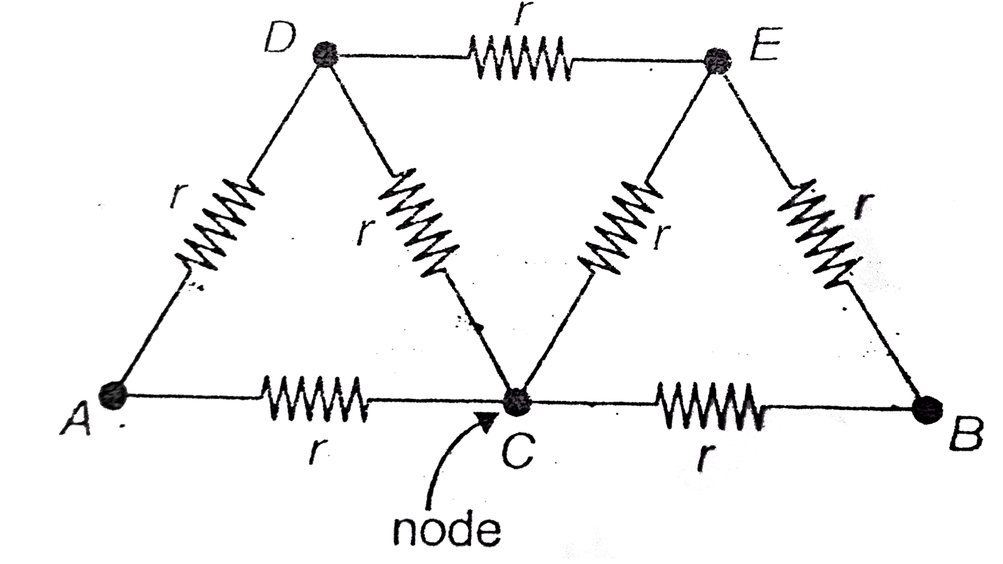
Strategy `:` (1) The symmetry suggests that current flowing from D to C will be equal to current flowing from C to E.
(2) Remove the node C and change the circuit as follows and find `R_(AB)`.
View SolutionFind the resistance of a wire frame shaped as cube (Fig) when measured between points (a) 1.7, (b) 1.2, (c) 1.3.
The resitance of each edge of the frame is `R`

View SolutionIn the given each of the segments has resistance R, EMF of battery is E and internal resistance is negligible. Find ratio of power generated in AE to that in HO.

View SolutionA galvanometer having 30 divisions has current sensitivity of `20 mu A//"division"`. Find the maximum current it can measure.
View SolutionTha scale of a galvanometer is divided into `150` equal divisions.The galvanometer has a current sensitivity of 10 divisions per mA and a voltage sensitivity of 2 divisions per mV . The galvanometer be designed to read (i) `6` A per division and (ii) `1 V` per division?
View SolutionThe galvanometer shown in figure has resistance 50 `Omega ` and current required for full scale deflection is 1mA. Find the resistance `R_(1),R_(2)` and required to convert to convert it into ammeter having ranges as indicated.
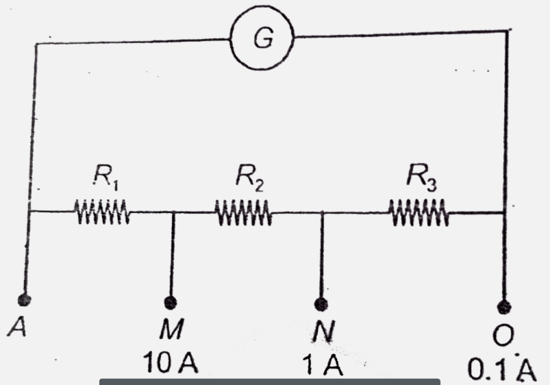
View SolutionIn the electrical circuits shown in figure (a) and figure (b) , the instruments are ideal in figure (a) while their resistance are marked in figure (b). Determine their readings.

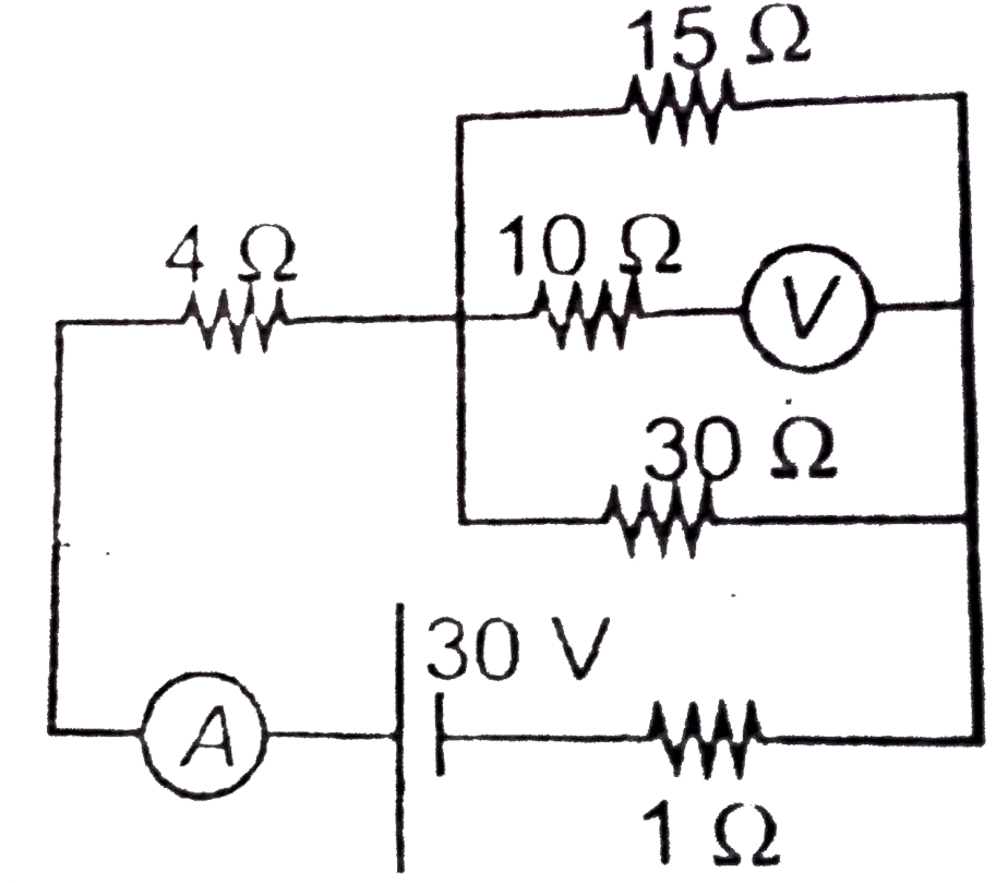
View SolutionIn the electrical circuit shown, the instrumets are ideal . Determine their readins.
View SolutionIn a potentiometer circuit, the emf of driver cell is 2V and internal resistance is `0.5 Omega `. The potentiometer wire is 1m long . It is found that a cell of emf 1V and internal resistance `0.5 Omega ` is balanced against 60 cm length of the wire. Calculate the resistance of potentiometer wire.
View SolutionFind the steady-state current `l_(1)` and `l_(2)` in the circuit drawn in figure. Also find the resistance of resistor `R_(3)` , that will give a steady -state current `l_(3) = 50 mA`. Finally , determine the potential drop across the capacior. The values of the known elements are `epsilon= 6V, R_(1) = 100 Omega, R_(2) = 80 Omega , ` and `C = 2 mu F `
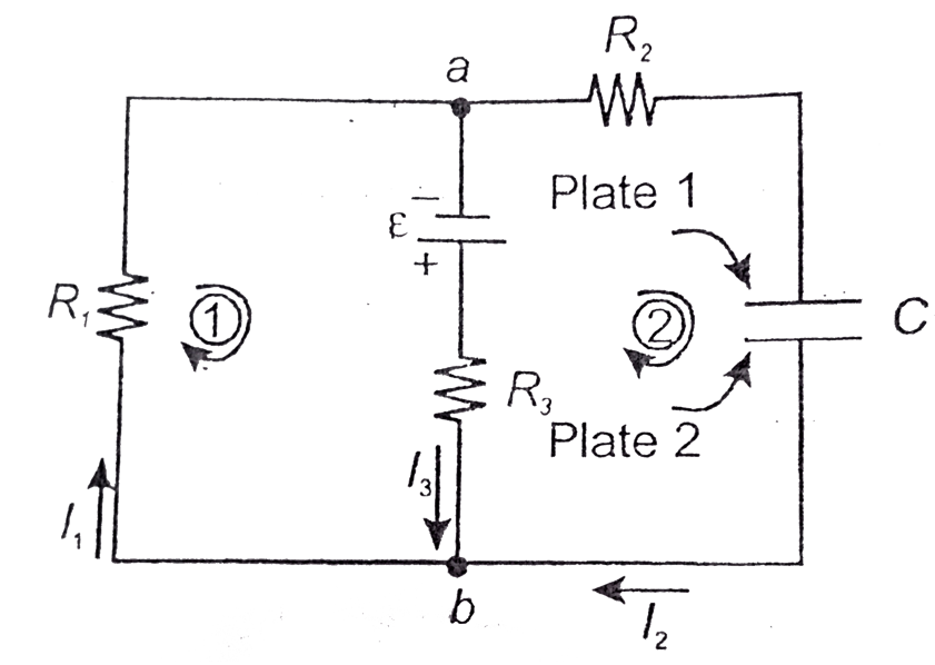
Strategy `:` A capacity acts as an open switch for steady-state current flow. Nevertheless, there is a voltage drop across the capacitor , because charge can build up on the capacitor plates under the impetus of the battery as the steady state is achieved . ( Once steady state is reached, there is no further build up of charge. ) We must accordingly include he capacitor in application of the loop rule, and we cannot simply ignore, for example , the loop (a-capacitor -b-a). There will therefore be two loop equations and one junction equation -with two junctions, there is always only one independent equation. With three equations, we will be able to solve for the three unknown `l_(1) ,R_(2)` and the potential drop across the capacitor.
View SolutionFind the energy stored in the capacitor using Kirchhoff's Laws.
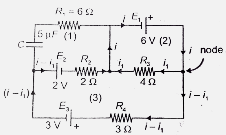
Strategy `:` Step-1 `:` Take the current from the batter of highest EMF
Step -2` :` Divide the total current into branch currents, keeping in mind that no current flows through capacitor.
Step-3 `:` Apply KVL to 3 loops shown in the figure.
Step -4 `:` Find the voltage across the capacitor using KVL
Step -5 ` :` Apply the formula `E = (1)/(2) CV^(2)` to find energy
View SolutionIn the electrical circuit shown, find the reading of ammeter (ideal) just after closing the switch and long time after closing the switch.

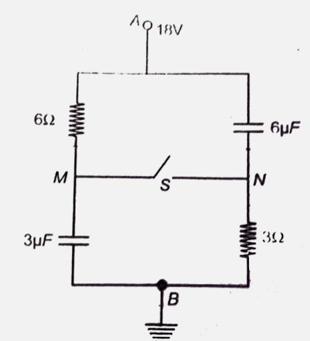
View SolutionFind `:`
(i) Potential differnece between points M and N when switch 'S' is open.
(ii) Potential of point N after long time when switch is closed.
(iii) How much does the charge after long time when S is closed ?
View SolutionA capacitor of capacitance C, which is initially uncharged , is connected with a battery of emf `epsilon`. Find the heat dissipated in the circuit during the process of charging .
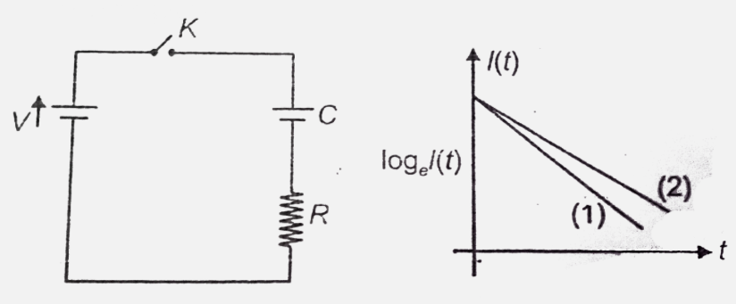
View SolutionConsider the circuit at t=0s, the kety K is closed . At t=1 s, the current is l(t), Graph (1) is the variation of `log_(e) l(t)` with time 't'. To obtain graph (2) , one of the parameters that is V, R or C is charged keeping the other two constant , What should be the change, to obtain graph (2) from graph (1) ?
View SolutionFind the time constant of the following RC circuit

View SolutionFind time constants of the following RC circuits.

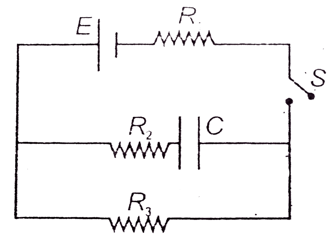
View SolutionFind time constant of the circuit when (a) S is closed . (b) S is open.
View Solution
EXAMPLE questions and complete solutions for chapter CURRENT ELECTRICITY of AAKASH INSTITUTE ENGLISH of Class 12
All Exercises from AAKASH INSTITUTE Class 12 PHYSICS CURRENT ELECTRICITY
- ASSIGNMENT SECTION-I(SUBJECTIVE TYPE QUESTIONS)
- ASSIGNMENT SECTION-B(OBJECTIVE TYPE QUESTION ))
- ASSIGNMENT SECTION-C(OBJECTIVE TYPE QUESTION ))
- ASSIGNMENT SECTION-D( LINKED COMPREHENSION TYPE QUESTIONS)
- ASSIGNMENT SECTION-D( LINKED COMPREHENSION TYPE QUESTIONS) Comprehension - II
- ASSIGNMENT SECTION-E (ASSERTION-REASON TYPE QUESTION)
- ASSIGNMENT SECTION-H ( MULTIPLE TRUE-FALE TYPE QUESTIONS)
- ASSIGNMENT SECTION-H( INTEGER ANSWER TYPE QUESTIONS)
- ASSIGNMENT SECTION-J
- ASSIGNMENT SECTION-J(MATRIX-MATCH TYPE QUESTIONS)
- ASSIGNMENT(SECTION-A(OBJECTIVE TYPE QUESTIONS))
- EXAMPLE
- Try Yourself