Complete Solutions to JEE Main And Advanced of chapter ELECTROMAGNETIC INDUCTION AND ALTERNATING CURRENT of Class 12 book with complete answers and questions
| Class 12 | PHYSICS |
| Chapter | ELECTROMAGNETIC INDUCTION AND ALTERNATING CURRENT |
| SUNIL BATRA | JEE Main And Advanced |
| Number Of Questions | 100 |
| Academic Year | 2023-24 |
A uniform wound solenoidal coil of self inductance `1.8xx10^(-4)` henry and resistance 6 ohm is broken up into two identical coils. These identical coils are then connected in parallel across a 15-volt battery of negligible resistance. The time constant for the current in the circuit is.......seconds and the steady state current through the battery is ..............amperes.
View SolutionIn a straight conducting wire, a constant current is flowing from left to right due to a source of emf. When the source is switched off, the direction of the induced current in the wire will.........
View SolutionAn e.m.f. Can be induced between the two ends of a straight copper wire when it is moved through a uniform magnetic field.
View SolutionA coil of metal wire is kept stationary in a non-uniform magnetic field. An e.m.f. Is induced in the coil.
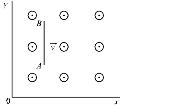
View SolutionA conducting rod AB moves parallel to the x-axis (see Fig.) in a uniform magnetic field pointing in the positive z-direction. The end A of the rod gets positively charged.
 .
.
View SolutionA thin circular ring of area A is held perpendicular to a uniform magnetic field of induction B. A small cut is made in the ring and a galvanometer is connected across the ends such that the total resistance of the circuit is R. When the ring is suddenly squeezed to zero area, the charge flowing through the galvanometer is
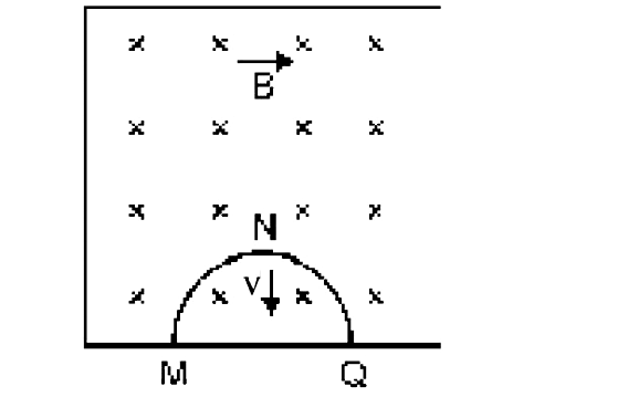
View SolutionA thin semi-circular conducting ring of radius R is falling with its plane verticle in horizontal magnetic induction `(vec B)`. At the position MNQ the speed of the ring is v, and the potential difference developed across the ring is
View SolutionTwo identical circular loops of metal wire are lying on a table without touching each other. Loop A carries a current which increases with time. In response, the loop B
View SolutionA coil of inductance 8.4 mH and resistance `6 (Omega)` is connected to a 12 V battery. The current in the coil is 1.0 A at approximately the time
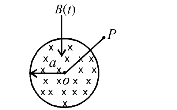
View SolutionA uniform but time-varying magnetic field B(t) exists in a circular region of radius a and is directed into the plane of the paper, as shown. The magnitude of the induced electric field at point P at a distance r from the centre of the circular region
View SolutionA coil of wire having inductance and resistance has a conducting ring placed coaxially within it. The coil is connected to a battery at time t=0, so that a time-dependent current `1_(1)(t)` starts following through the coil. If `I_(2)(t)` is the current induced in the ring, and B (t) is the magnetic field at the axis of the coil due to `I_(1)(t)` then as a function of time `(tgt0)`, the product `I_(2)(t)B(t)`
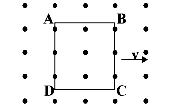
View SolutionA metallic square loop ABCD is moving in its own plane with velocity v in a uniform magnetic field perpendicular to its plane as shown in the figure. An electric field is induced
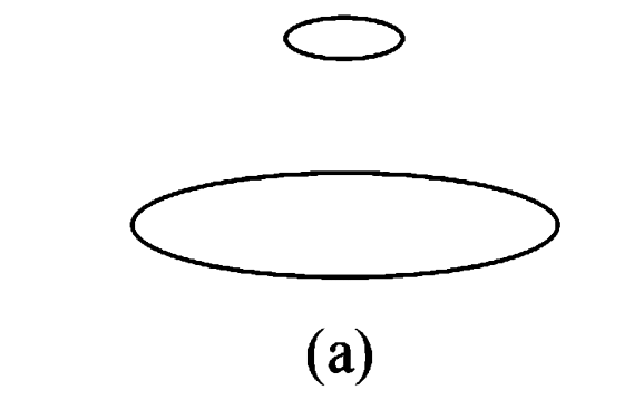
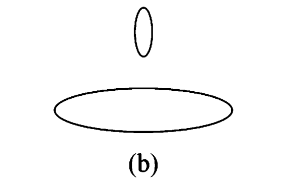
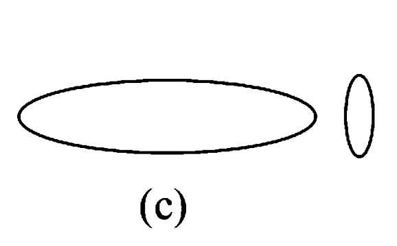
View SolutionTwo circular coils can be arranged in any of the three situation shown in the figure. Their mutual inductance will be
 ,
,  ,
, 
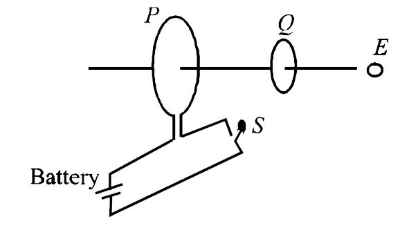
View SolutionAs shown in the figure, P and Q are two coaxial conducting loops separated by some distance. When the switch S is closed, a clockwise current `I_(P)` (as seen by E) and an induced current `I_(Q1)` flows in Q. The switch remains closed for a long time. when S is opened, a current `I_(Q2)` flows in Q. Then the direction `IQ_(1) and IQ_(2)` (as seen by E) are
View SolutionA short-circuited coil is placed in a time-varying magnetic field. Electrical power is dissipated due to the current induced in the coil. If the number of turns were to be quadrupled and the wire radius halved, the electrical power dissipated would be
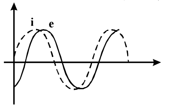
View SolutionWhen an AC source of `emf e=E_(0) sin(100t)` is connected across a circuit i in the circuit, the phase difference between the emf e and the current i in the circuit is observed to be `(pi//4)`, as shown in the diagram. If the circuit consists possibly only of R-C or R-L or L-C in series, find the relationship between the two elements
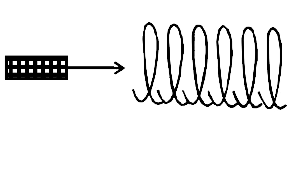
View SolutionA small bar magnet is being slowly inserted with constant velocity inside a solenoid as shown in figure. Which graph best represents the relationship between emf induced with time
View SolutionAn infinitely long cylinder is kept parallel to an uniform magnetic field B directed along positive z-axis. The direction of induced current as seen from the z-axis will be
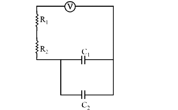
View SolutionFind the time constant `(in ) fo the given RC circuits in the given order respectively
 ,
,

`(R_1)=1 Omega, (R_2)=2 Omega, C_(1)=4 muF, C_(2)=2 mu F`
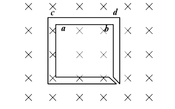
View SolutionThe figure shows certain wire segments joined together to form a coplaner loop. The loop is placed in a perpendicular magnetic field in the direction going into the plane of the figure. The magnitude of the field increases with time `I_(1) and I_(2)` are the currents in the segments ab and cd. Then,
View SolutionAn AC voltage source of variable angular frequency `(omega)` and fixed amplitude `V_(0)` is connected in series with a capacitance C and an electric bulb of resistance R (inductance zero). When `(omega)` is increased
View SolutionL, C and R represent the physical quantities, inductance, capacitance and resistance respectively. The combination(s) which have the dimensions of frequency are
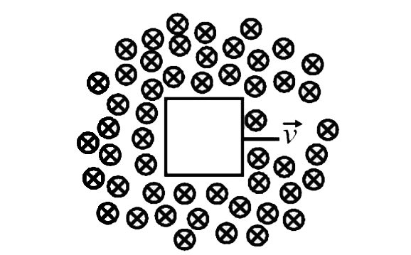
View SolutionA conducting square loop of side L and resistance R moves in its plance with a uniform velocity v perpendicular to one of its sides. A magnetic induction B, constant in time and space, pointing perpendicular and into the plane of the loop exists everywhere.
The current induced in the loop is
View SolutionTwo different coils have self-inductances `L_(1) = 8 mH and L_(2) = 2 mH`. The current in one coil is increased at a constant rate. The current in the second coil is also increased at the same constant rate. At a certain instant of time, the power given to the two coil is the same. At that time, the current, the induced voltage and the energy stored in the first coil are `i_(1), V_(1) and W_(1)` respectively. Corresponding values for the second coil at the same instant are `i_(2), V_(2) and W_(2)` respectively. Then:
View SolutionA small square loop of wire of side l is placed inside a large square loop of wire of side `L(Lgtgtl)`. The loops are co-planer and their centres coincide. The mutual inductance of the system is proportional to
View SolutionThe SI unit of inductance, the henry, can be written as
View SolutionA metal rod moves at a constant velocity in a direction perpendicular to its length. A constant, uniform magnetic field exists in space in a direction perpendicular to the rod as well as its velocity. Select the correct statements(s) from the following
View SolutionA sereis R-C circuit is connected to AC voltage source. Consider two cases, (A) when C is without a dielectric medium and (B) when C is filled with dielectric of constant 4. The current `I_(R)` through the resistor and voltage `V_(c)` across the capacitor are compared in the two cases. Which of the following is/ are true?
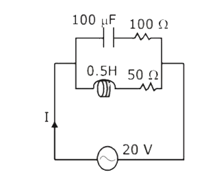
View SolutionIn the given circuit, the AC source has `omega` = 100 rad/s. Considering the inductor and capacitor to be ideal, the correct choice(s) is (are)
View SolutionA current-carrying infinitely long wire is kept along the diameter of a circular wire loop, without touching it. The correct statement(s) is (are)
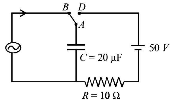
View SolutionAt time `t = 0`, terminal A in the circuit shown in the figure is connected to B by a key and an alternating current `I(t) = I_(0)cos (omega t)`, with `I_(0) = 1 A and (omega) = 500 rads^(-1)` starts flowing in it with the initial direction shown in the figure. At `t = (7pi//6omega)`, the key is switched from B to D. Now onwards only A and D are connected. A total charge Q flows from the battery to charge the capacitor fully. If `C=20(mu)F, R = 10(Omega) and the battery is ideal with emf of 50 V, identify the correct statement(s).
 .
.
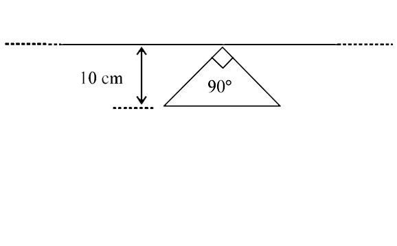
View SolutionA conducting loop in the shape of a right angled isosceles triangle of height 10 cm is kept such that `90^@` vertex is very close to an infinitely long conducting wire (see the figure). The wire is electrically insulated from the loop. The hypotenuse of the triangle is parallel to the wire. Current in the triangular loop is in counterclockwise direction and increased at a constant rate of `10 A s^(-1)`. Which of the following statement(s) is(are) true?
 .
.
View SolutionA rigid wire loop of square shape having side of length L and resistance R is moving along the x-axis with a constant velocity `v_(0)` in the plane of the paper. At `t =0`, the right edge of the loop enters a region of length 3L where there is a uniform magnetic field `B_(0)` into the plane of the paper, as shown in the figure. For sufficiently large `v_(0)` the loop eventually crosses the region. Let x be the location of the right edge of the loop. Let v(x), I(x) and F(x) represent the velocity of the loop, current in the loop, and force on the loop, respectively, as a function of x. Counter-clockwise current is taken as positive.
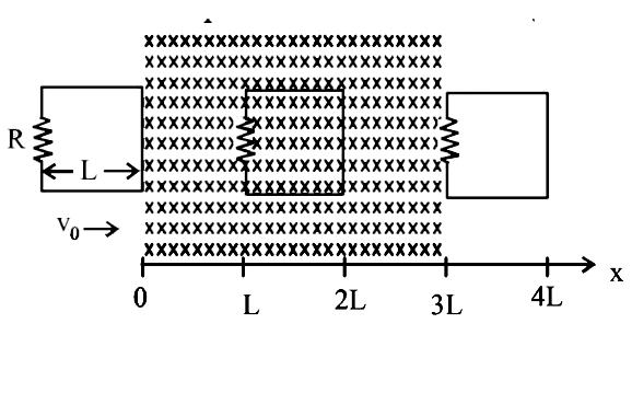 . Which of the following schematic plot(s) is (are) correct? (Ignore gravity)
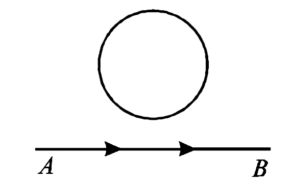
View SolutionA current from A to B is increasing in magnitude. What is the direction of induced current. If any,in the loop as shown in the figure?
View SolutionThe two rails of a railway track, insulated from each other and the ground, are connected to a milli voltmeter. What is the reading of the milli voltmeter when a train travels at a speed of `180 km//hours along the track, given that the vertical components of earth's magnitic field is `0.2xx10^(_4) weber//m^(2)` & the rails are separated by 1 meter?
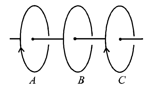
View SolutionThree indentical closed coils A,B and C are placed with their planes parallel to one another. Coils A and C carry equal currents as shown in fig. Coils B and C are fixed in position and coil A is moved towards B with uniform motion. Is there any indenced current in B? If no, give reasons. If yes mark the direction of the induced current in he diagram.
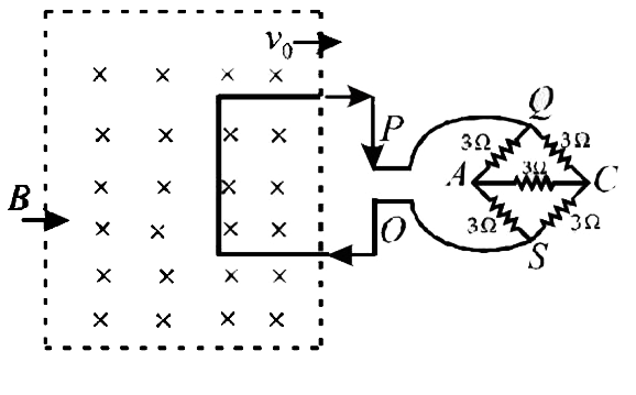
View SolutionA square metal wire loop of side 10 cm and resistance 1 ohm is moved with a constant velocity `(v_0)` in a uniform magnetic field of induction `B=2 weber//m^(2)` as shown in the figure. The magnetic field lines are perpendicular to the plane to the loop (directed into the paper). The loop is connected to a network of resistors each of value 3 ohms. The resistances of hte lead wire OS and PQ are negligible. What should be the speed of the loop so as to have a steady current of 1 milliampere in the loop? Given the direction of current in the loop.
View SolutionSpace is divided by the line AD into two regions. Region I is field free and the Region II has a unifrom magnetic field B direction into the plane of the paper. ACD is a simicircular conducting loop of radius r with center at O, hte plane of the loop being in the plane of the paper. The loop is now made to rotate with a constant angular velocity `omega` about an axis passing through O and the perpendicular to the plane of the paper. The effective resistance of the loop is R.
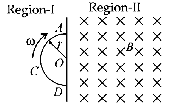
(i) obtain an expression for hte magnitude of the induced cureent in the loop.
(ii) Show the direction of the current when the loop is entering into the Rigion II.
Plot a graph between the induced e.m.f and the time of roation for two periods or rotation.
View SolutionTwo long parallel horizontal rails a, a distance d aprt and each having a risistance `lambda` per unit length are joing at one end by a resistance R. A perfectly conduction rod MN of mass m is free to slide along the rails without friction (see figure). There is a uniform magnetic field of induction B normal to the plane of the paper and directed into the paper. A variable force F is applied to the rod MN such that, as the rod moves a constant current flows through R.
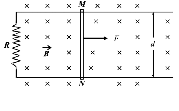
(i) Find the velocity of the rod and the applied force F as function of the distance x of the rod from R.
(ii) What fraction of the work done per second by F is converted into heat?
View SolutionA circuit containing a two position switch S is shown in fig.
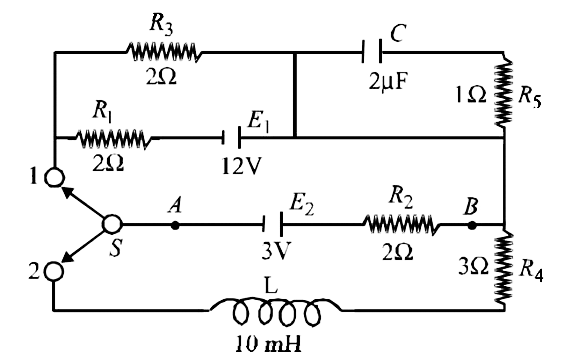
(a) The switch S is in position '1'. Find the potential difference `V_(A)-V_(B)` and the rate of production of joule heat in `(R_1)`.
(b) If now the switch S is put in position 2 at t=0 find
(i) steady current in `(R_4)` and
(ii) the time when current in `(R_4)` is half the steady value.
Also calculate the energy stroed in the inductor L at that time.
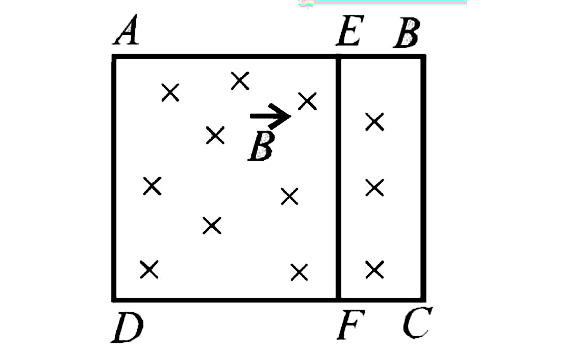
View SolutionA rectangular frame ABCD, made of a uniform metal wire, has a straight connection between E and F made of the samae wire, as shown in fig. AEFD is a square of side 1m, and EB=FC=0.5m. The entire circuit is placed in steadily increasing, uniform magnetic field directed into the plane of the paper and normal to it. The rate of change of the magnetic field is `1T//s`. The resistance per unit length of the wire is `1omega//m`. Find the magnitude and directions of the currents in the segments AE, BE and EF.
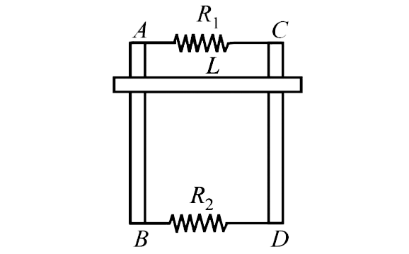
View SolutionTwo parallel vertical metallic rails AB and CD are separated by 1m. They are connected at two ends by resistanace `(R_1) and (R_2)` as shown in fig. A horizontal metallic bar L of mass 0.2 kg slides without froction vertically down the rails under the action of gravity. THere is a uniform horizontal magnetic field of 0.6 Tesla perpendicular to the plane of the rails. It is observed taht when the teminal velocity is attained, the power dissipated in `(R_1) and (R_2)` are 0.6 watt and 1.2 watt respectively. Find the terminal velocity of the bar L and the values of `(R_1)and (R_2)`.
View SolutionA metal rod OA of mann 'm' and length 'r' is kept rotating with a constantangular speed `omega` in a vertical plane about a horizontal axis at the end O. The free end A is arraged to slide without friction along fixed conduction circular ring in the same plane as that of rotation. A uniform and constant magnetic induction `vec(B)` is applied perpendicular and into the plane of rotation as shown in the figure below. An inductor L and an external resistance R are connected through a swithch S between the point O and a point C on the ring to form an electrical circuit. Neglect the resistance of the ring and the rod. Initially, the switch is open.
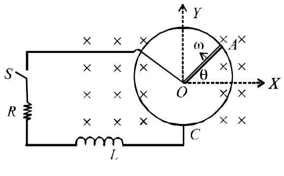
(a) What is the induced emf across the teminal of the switch?
(b) The switch S is closed at time t=0.
(i) Obtain an expression for the current as a function of time.
(ii) In the steady state, obtin the time dependence of the torque required to maintain the constant angular speed, given that the rod OA was along th positive X-axis at t=0.
View SolutionA solenoid has an inductance of 10 henty and a resistance of 2 ohm. It is connected to a 10 volt battery. How long will it take for the magnetic energy to reach `1//4` of its maximum value?
View SolutionA pair of parallel horizontal conducting rails of negligible resistance shorted at one end is fixed on a table. The distance between the rails is L. A conducting massless rod of resistance R can slide on the rails frictionlessly. The rod is tied to a massless string which passes over a pulley fixed to the edge of the table, A mass m, tied to the other end of the string hanges vertically. A constant magnetic field B exists perpendicular to the table. If the system is released from rest, calculate.
(i) the terminal velocity achieved by the rod, and
the acceleration of the mass at the instant when the velocity of the rod is half the terminal velocity.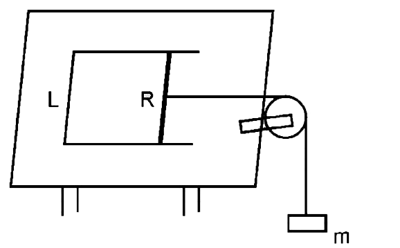
View SolutionA magnetic field `B = B_(0) (y/a)hatk` is into the paper in the +z direction, `B_(0)` and a are positive constants. A square loop EFGH of side a, mass m and resistance R, in x-y plane, starts falling under the influence of gravity see figure. Note the direction of x and y axis in figure.
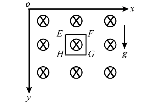
Find
(a) the induced current in the loop and indicate its direction.
(b) the total Lorentz force acting on the loop and indicate its direction, and
(c) an expression for the speed of the loop, v(t) and its terminal value.
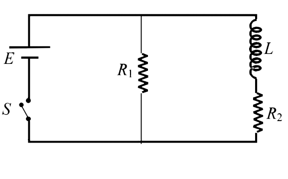
View SolutionAn inductor of inductance L=400 mH and resistor of resistance `R_(1) = 2(Omega) and R_(2) = 2 (Omega)` are connected to a battery of emf E = 12 Vas shown in the figure. The internal resistance of the battery is negligible. The switch S is closed at time t =0. What is the potential drop across L as a function of time? After the steady state is reached, the switch is opened. What is the direction and the magnitude of current through `R_(1)` as a function of time?
View SolutionA rectangular loop PQRS made from a uniform wire has length a, width b and mass m. It is free to rotate about the arm PQ, which remains hinged along a horizontal line taken as the y-axis (see figure). Take the vertically upward direction as the z-axis. A uniform magnetic field `vec(B) = (3 hat(i) + 4 hat(k)) B_(0)` exists in the region. The loop is held in the x-y plane and a current I is passed through it. The loop is now released and is found to stay in the horizontal position in equilibrium
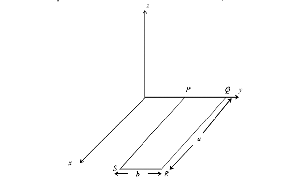
(a) What is the direction of the current I in PQ?
(b) Find the magnetic force on the arm RS.
(c) Find the expression for I in terms of `B_(0)`, a, b and m
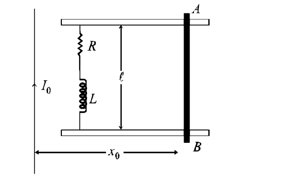
View SolutionA metal bar AB can slide on two parallel thick metallic rails separated by a distance l. A resistance R and an inductance L are connected to the rails as shown in the figure. A long straight wire carrying a constant current `I_(0)` is placed in the plane of the rails and perpendicular to them as shown. The bar AB is held at rest at a distance `x_(0)` from the long wire. At t=0, it is made to slide on the rails away from wire. Answer the following questions.
(a) Find a relation among `i, (di)/(dt) and (d phi)/(dt)`, where i is the current in the circuit and `phi` is the flux of the megnetic field due to the long wire through the circuit.
(b) It is observed that at time t=T, the metal bar AB si at a distance of `2x_(0)` from the long wire and the resistance R carries a current `(i_1)`. Obtain an expression for the net charge that has flown through riesistance R form t=0 to t=T.
(c) THe bar is suddenly stopped at time T. THe current through resistance R is found to be `(i_1)/(4)` at time 2T. Find the value of `L/R` in terms of hte other given quantities.
View SolutionA square loop of side 'a' with a capacitor of capacitance C is located between two current carrying long parallel wires as shown. The value of I in the wires in given as `I=(I_0) sin omega t`.
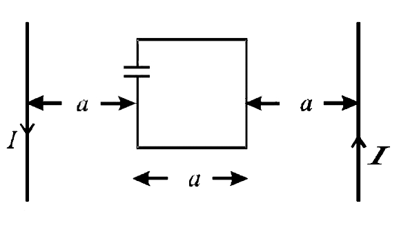
(a) Calculate maximum current in the square loop.
(b) Draw a graph between charges on the upper plates of the capacitor vs time.
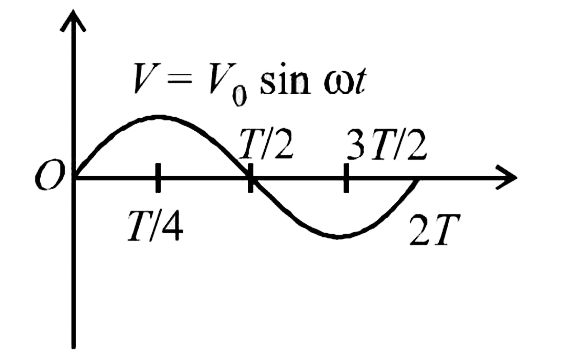
View SolutionIn a series L-R circuit `(L=35 mH and R=11 Omega)`, a variable emf source `(V=V_(0) sin omega t)` of `V_(rms)=220V` and frequency 50 Hz is applied. Find the current amplitude in the circuit and phase of current with respect to voltage. Draw current-time graph on given graph `(pi=22/7)`.
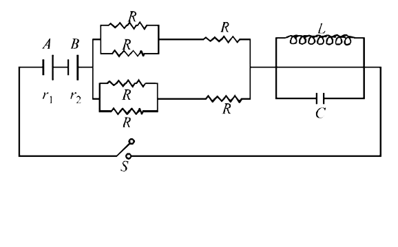
View SolutionIn the figure both cells A and B are of equal emf. Find R for which potential difference across battery A will be zero, long time after the switch is closed. Internal resistance of batteries A and B `(r_1) and (r_2)` respectively`(r_(1)gtr_(2))`.
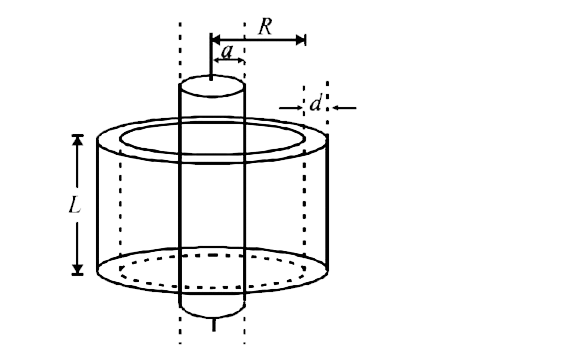
View SolutionA long solenoid of radius a and number of turns per unit length n is enclosed by cylindrical shell of radius R. Thickness d(dltltR) and length L. A variable current `i=i_(0) sin omega t` flows through the coil. If the resistivity of the material of cylindrical shell is `(rho)`, find the induced current in the shell.
View SolutionIn the given circuit the capacitor (C) may be charged through resistance R by a battery V by closing switch `(S_1)`. Also when `(S_1)` is opend and `(S_2)` is closed the capacitor is connected in series with inductor (L).
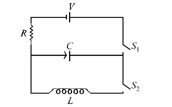
At the start, the capicitor was uncharged. when switch `(S_1)` is closed and `(S_2)` is kept open, the time constant of this circuit is `tau`. which of the following is correct
View SolutionIn the given circuit the capacitor (C) may be charged through resistance R by a battery V by closing switch `(S_1)`. Also when `(S_1)` is opend and `(S_2)` is closed the capacitor is connected in series with inductor (L).
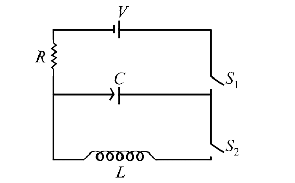
When the capacitor gets charged compleely, (=`(S_1)` is opened and `(S_2)` is closed, Then,
View SolutionIn the given circuit the capacitor (C) may be charged through resistance R by a battery V by closing switch `(S_1)`. Also when `(S_1)` is opend and `(S_2)` is closed the capacitor is connected in series with inductor (L).
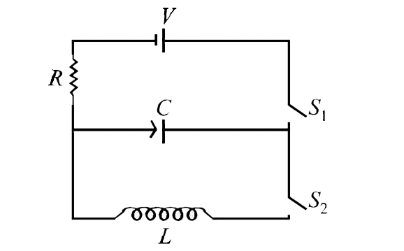
Given taht the total charge stored in the LC circuit is `(Q_0)`. for `Tge0, the charge on the capacitor is
View SolutionA thermal power plant produed electric power of 600kW at 4000V, which is to be transported to a place 20 km away form the power plant for consumer's usage. It can be transported either directly with a cable of large current carrying capacity or by sing a combination of step-up and step-down transfprmers at the two ends. THe drawback of the direct transmission is the large energy dissipation. In the method wsing transformers, the dissipatiion is much smaller. In this method a step-up transformers is used at the plant side so that the current is reduced to a smaller value. At the consumers'end, a step-down transformer is used to supply power to the consumers at the specified lower voltage. It is reasonable to assume that the power cable is purely resostive and the transformers are ideal with power factor unity. All the currents and voltagementioned are values.
If hte direct transmission method with a cable of resistance `0.4(omega) km^(-1)` is used, the power dissipation (in %) during transmission is
View SolutionA thermal power plant produed electric power of 600kW at 4000V, which is to be transported to a place 20 km away form the power plant for consumer's usage. It can be transported either directly with a cable of large current carrying capacity or by sing a combination of step-up and step-down transfprmers at the two ends. THe drawback of the direct transmission is the large energy dissipation. In the method wsing transformers, the dissipatiion is much smaller. In this method a step-up transformers is used at the plant side so that the current is reduced to a smaller value. At the consumers'end, a step-down transformer is used to supply power to the consumers at the specified lower voltage. It is reasonable to assume that the power cable is purely resostive and the transformers are ideal with power factor unity. All the currents and voltagementioned are values.
In the method using the transformers assume that the ratio of the number of turns in the primary to that in the secondary in the step-up transformer is 1:10 if the power to the consumers has to be supplied at 200V, the ratio of the number of turns in the primary to that in the secondary in the step-down transformer is
View SolutionA point charges Q is moving in a circular orbit of radius R in the x-y plane with an angular velocity `omega`. This can be considered as equivalent to a loop carrying a steady current `(Q omega)/(2 pi)`. S uniform magnetic field along the positive z-axis is now switched on, which increases at a constant rate from 0 to B in one second. Assume that the radius of hte orbit remains constant. The application of hte magnetic field induces an emf in the orbit. The induced emf is defined as the work done by an induced electric field in moving a unit positive charge around a closed loop. It si known that, for an orbiting charge, the magnetic dipole moment is proportional to the angular momentum with a porportionality constant `lambda`.
The charge in the magnetic dipole moment associated with the orbit. at the end of the time interval of hte magnetic field charge, is
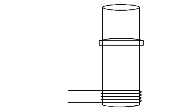
View SolutionStatement-1: A vertical iron rod has ciol of wire wound over it at the bottom end. An alternating current flows in the coil. The rod goes through a conduction ring as shwon in the figure. The ring can float at a certain height above the coil.
Statement -2: In the above situation a current is inuced in the ring which interacts with the horizontal components of the magnetc field to produce an aberage force in the upward direction.
View SolutionA series R-C combination is connected to an AC voltage of angular frequency `omega=500 radian//s`. If the impendance of the R-C circuit is `Rsqrt(1.25)`, the time constant (in millisecond) of the circuit is
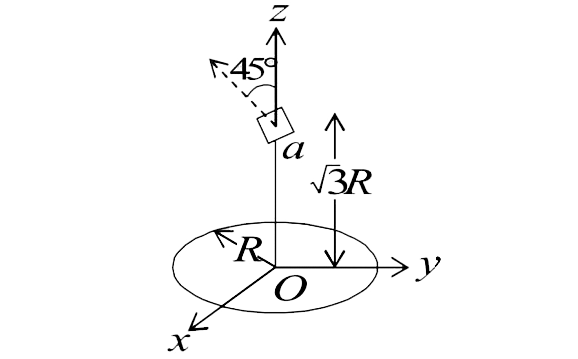
View SolutionA circular wire loop of radius R is placed in the x-y plane centered at the origin O. A square loop of side a`(altltR)` having two turns is placed with its centre at `=sqrt(3)R` along the axis of hte circular wire loop, as shown in figure. The plane of the square loop makes an angle of `45^(@)` with respect to the z-axis. If the mutual inductance between the loops is given bu `(mu_(0)a^(2))/(2^(p//2)R)`, then the value of p is
View SolutionTwo inductors `L_(1)`(inductors 1 mH, internal resistance 3 `Omega`) and `L_(2)` (inductance 2mH, internal resistance 4`Omega`),and a resistor R(resistance`12 omega`) are all connected in parallelacross a 5 V battery. The circuit is switched on at time t=0. The ratio of the maximum to the minimum current `(I_(max)//I_(min))` drawn from the battery is
View SolutionThe power factor of an AC circuit having resistance (R) and inductance (L) connected in series and an angular velocity `omega` is
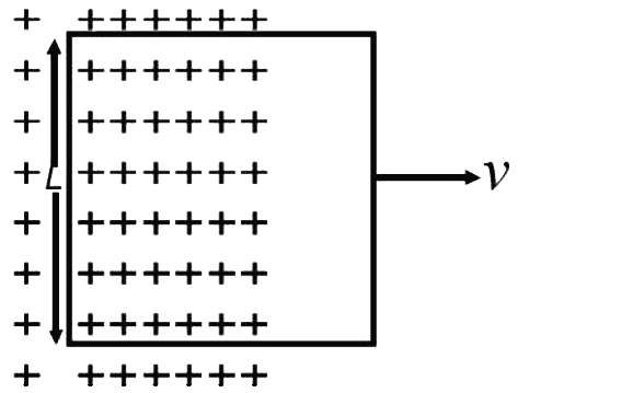
View SolutionA conduting square loop of side L and resistnce R moves in its plane with a uniform velocity v perpendicular to one of its sides. A magnitude induction B constant in time and space, pointing perpendicular and into to plane at the loop exists every with half the loop outside the field, as shown in figure. The induced emf is
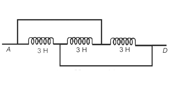
View SolutionThe inductance between A and D is
View SolutionIn a transformer, number of turns in the primary coil are 140 and that in the secondry coil are 280. If current i primary coil is 4A, then that in the secondary coil is
View SolutionTwo coil are placed close to each other. The mutual inductance of the pair of coils depends upon.
View SolutionWhen the current changes from +2A to -2A in 0.5 second an emf of 8V is induced in a coil. The coefficient of selfinduction of the coil is
View SolutionIn an oscillating LC circuit the maximum charge on the capacitor is Q. The charges on the capacitor when the energy is stored equally between the electric and magnetic field is
View SolutionThe core of any transformaer is laminated so as to
View SolutionAlternating current can not be measured by D.C. Ammeter because
View SolutionIn an LCR series a.c. Circuit the voltage across each of hte components L,C and R is 50V. The voltage across the LC combination will be
View SolutionA coil having n turns and resistance `R Omega` is connected with a galvanometer of resistance `4R Omega`. This combination is moved in time t seconds from a magnetic field `W_(1)` weber to `W_(2)` weber. The induced current in the circuit is
View SolutionIn a uniform magneitc field of induced B a wire in the form of a semicircle of radius r rotates about the diameter of the circle with an angular frequency `omega`. The axis of rotation is perpendicular to the field. If the total resistance of the circuit is R, the mean power generated per period of rotation is
View Solutionin a LCR circuit capacitance is chagned from C to 2C. For the resomat frequency to remain unchaged, the inductance should be chagned from L to
View SolutionA metal conductor of length 1m rotates vertically about one of its ends at angular velocity 5 radians per second. If the horizontal component of earth's magnetic field is `0.2xx10^(-4)T`, then the emf developed between the two ends of hte conductor is
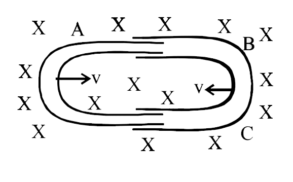
View SolutionOne conducting U tube can slide inside another as shown in figure, maintaining electrical contacts between the tubes. The magnetic field B is perpendicular to the plane of the figure. If each tube maoves towards the other at a constant speed v. Then the emf induced in the circuit in terms of B, l and v where l is the width of each tube will be
View SolutionThe self inductance of the motor of an electric fan is 10H. In order to impart maximum power at 50 Hz, it should be connected to a capacitance of
View SolutionThe phase diffenernce between the alternating current and emf is `(pi)/(2)`. Which of the following cannot be the constiuent of the circuit?
View SolutionA circuit has a resistance of 12 ohm and an impendance of 15 ohm. The power factor of the circuit will be
View SolutionA coil of inductance 300mH and resistance `2 Omega. The current reaches half of its steady state value in
View SolutionWhich of the following units denotes the dimension `(ML^(2))/(Q^(2))`, where Q denotes the electric charge?
View SolutionIn a series resonant LCR circuit the voltage across R is 100 volts and R = `1 k(Omega) with C =2(mu)F`. The resonant frequency `(omega)` is `200 rad//s`. At resonance the voltage across L is
View SolutionIn an AC generator, a coil with N turns, all of the same area A and total resistance R, rotates with frequency `(omega)` in a magnetic field B. The maximum value of emf generated in the coils is
View SolutionThe flux linked with a coil at any instant 't' is given by `phi = 10t^(2) - 50t +250`
The induced emf at `t = 3s` is
View SolutionAn inductor `(L = 100 mH)`, a resistor `(R = 100 (Omega))` and a battery `(E = 100 V)` are initially connected in series as shown in the figure. After a long time the battery is disconnected after short circuiting the point A and B. The current in the circuit 1 ms after the short circuit is
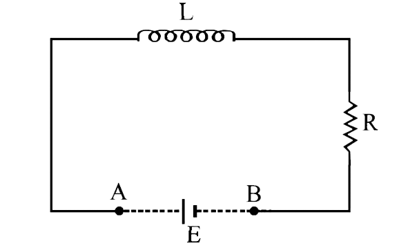
View SolutionIn an a.c. Circuit the voltage applied is `E=E_(0) sin (omega)t`. The resulting current in the circuit is `I=I_(0)sin((omega)t-(pi/2))`. The power consumption in the circuit is given by
View SolutionAn ideal coil of 10H is connected in series with a resistance of `5(Omega)` and a battery of 5V. 2second after the connections is made, the current flowing in ampere in the circuit is
View SolutionTwo coaxial solenoids are made by winding thin insulated wire over a pipe of cross-sectional area `A=10 cm^(2)` and length =20cm. If one of the solenoid has 300 turns and the other 400 turns, their mutual indcutance is
View SolutionAn inductor of inductance L=400 mH and resistor of resistance `R_(1) = 2(Omega) and R_(2) = 2 (Omega)` are connected to a battery of emf E = 12 Vas shown in the figure. The internal resistance of the battery is negligible. The switch S is closed at time t =0. What is the potential drop across L as a function of time? After the steady state is reached, the switch is opened. What is the direction and the magnitude of current through `R_(1)` as a function of time?

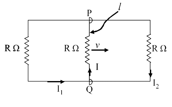
View SolutionA rectangular loop has a sliding connector PQ of length l and resistance `R (Omega)` and it is moving with a speed v as shown. The set-up is placed in a uniform magnetic field going into the plane of the paper. The three currents `I_(1), I_(2)` and I are
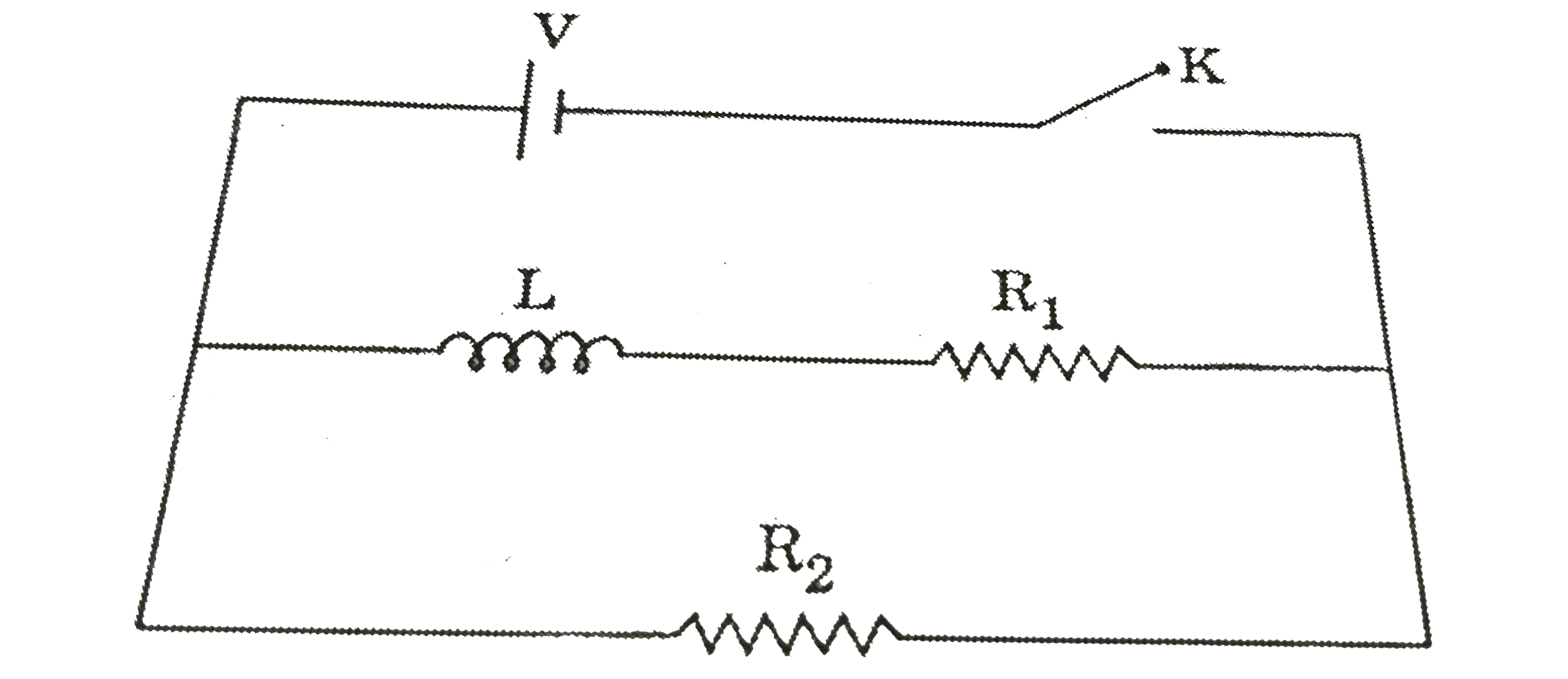
View SolutionIn the circuit shown below, the key K is closed at t = 0. The current through the battery is
View SolutionIn a series LCR circuit `R= 200(Omega)` and the voltage and the frequency of the main supply is 220V and 50 Hz respectively. On taking out the capacitance from the circuit the current lags behind the voltage by `30(@)`. On taking out the inductor from the circuit the current leads the voltage by `30(@)`. The power dissipated in the LCR circuit is
View SolutionA boat is moving due east in a region where the earth's magnetic field is `5.0xx10^(-5) NA^(-1)m^(-1)` due north and horizontal. The boat carries a vertical aerial 2 m long. If the speed of the boat is `1.50 ms^(-1)`, the magnitude of the induced emf in the wire of aerial is
View SolutionA fully charged capacitor C with initial charge `q_(0)` is connected to a coil of self inductance L at t=0. The time at which the energy is stored equally between the electric and the magnetic fields is
View SolutionA resistor 'R' and `2(mu)F` capacitor in series is connected through a switch to 200 V direct supply. A cross the capacitor is a neon bulb that lights up at 120 V. Calculate the value of R to make the bulb light up 5 s after the switch has been closed. (`log_(10) 2.5 = 0.4`)
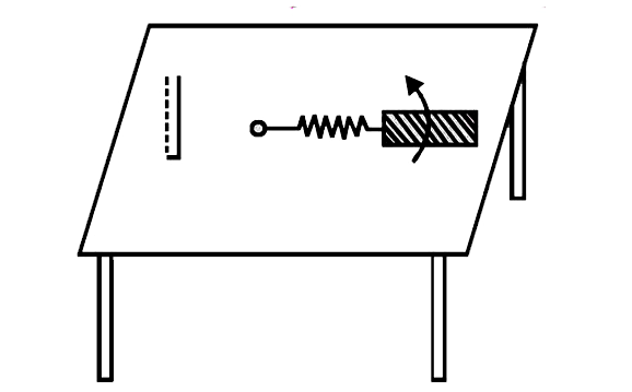
View SolutionA coil is suspended in a uniform magnetic field, with the plane of the coil parallel to the magnetic lines of force. When a current is passed through the coil it starts oscillating, It is very difficult to stop. But if an aluminium plate is placed near to the coil, it stops. This is due to :
View SolutionA metallic rod of length 'l' is tied to a string of length 2l and made to rotate with angular speed w on a horizontal table with one end of the string fixed. If there is a vertical magnetic field 'B' in the region, the e.m.f. Induced across the ends of the rod is
View Solution
JEE Main And Advanced questions and complete solutions for chapter ELECTROMAGNETIC INDUCTION AND ALTERNATING CURRENT of SUNIL BATRA 41 YEARS IITJEE PHYSICS (HINGLISH) of Class 12
