Complete Solutions to Linked Comprehension of chapter WAVE OPTICS of Class 12 book with complete answers and questions
| Class 12 | PHYSICS |
| Chapter | WAVE OPTICS |
| CENGAGE PHYSICS | Linked Comprehension |
| Number Of Questions | 88 |
| Academic Year | 2023-24 |
A narrow tube is bent in the form of a circle of radius R, as shown in figure. Two small holes S and D are made in the tube at the position at right angle to each other. A source placed at S generates a wave of intensity `I_(0)` which two parts: one part travels along the longer path, while the other travels along the shorter path. Both the waves meet at point D where a detector is placed.
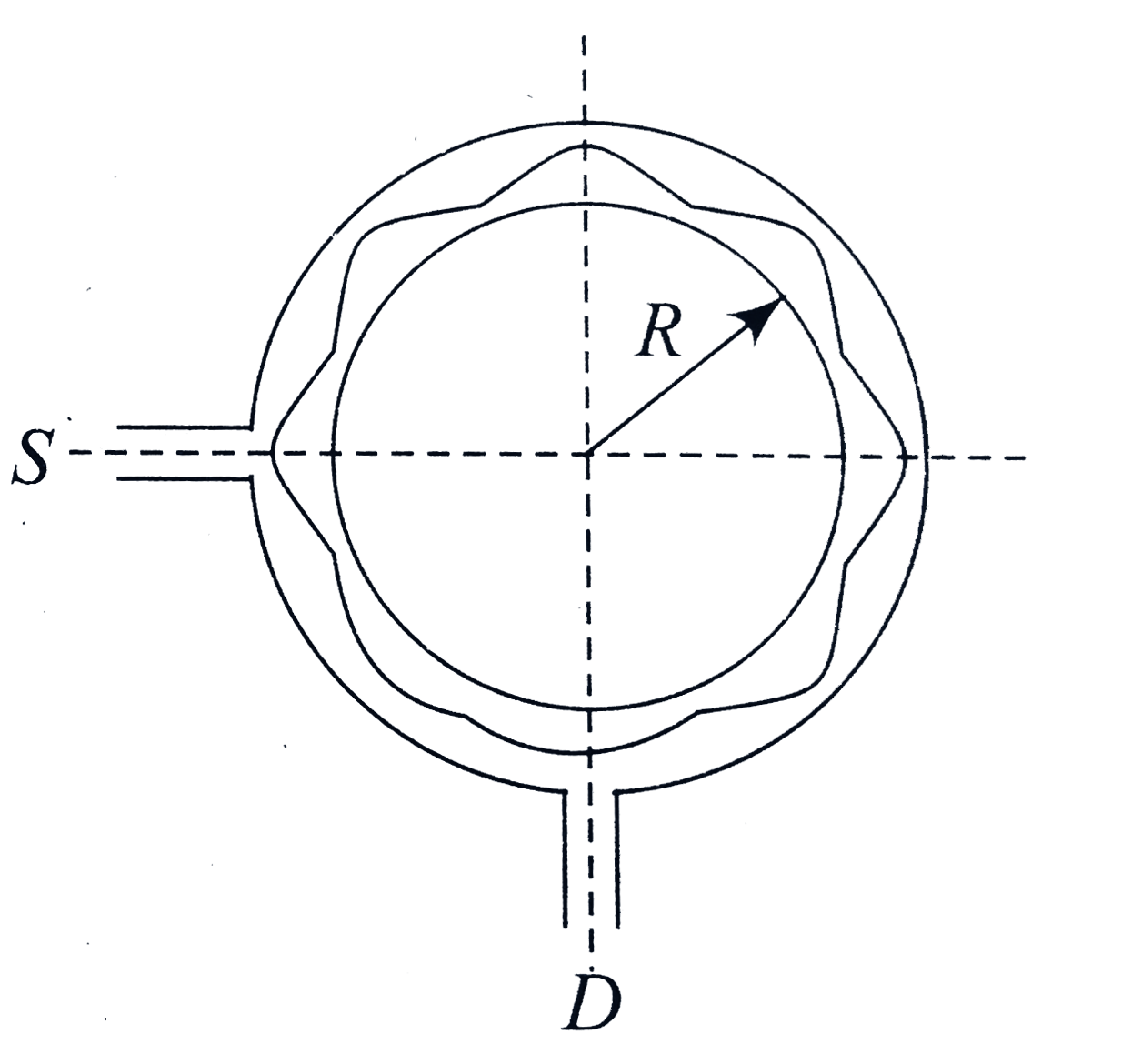
1. If a maxima if formed at a detector, then the magnitude of wavelength `lambda` of the, wave produced is given by
View SolutionA narrow tube is bent in the form of a circle of radius R, as shown in figure. Two small holes S and D are made in the tube at the position at right angle to each other. A source placed at S generates a wave of intensity `I_(0)` which two parts: one part travels along the longer path, while the other travels along the shorter path. Both the waves meet at point D where a detector is placed.
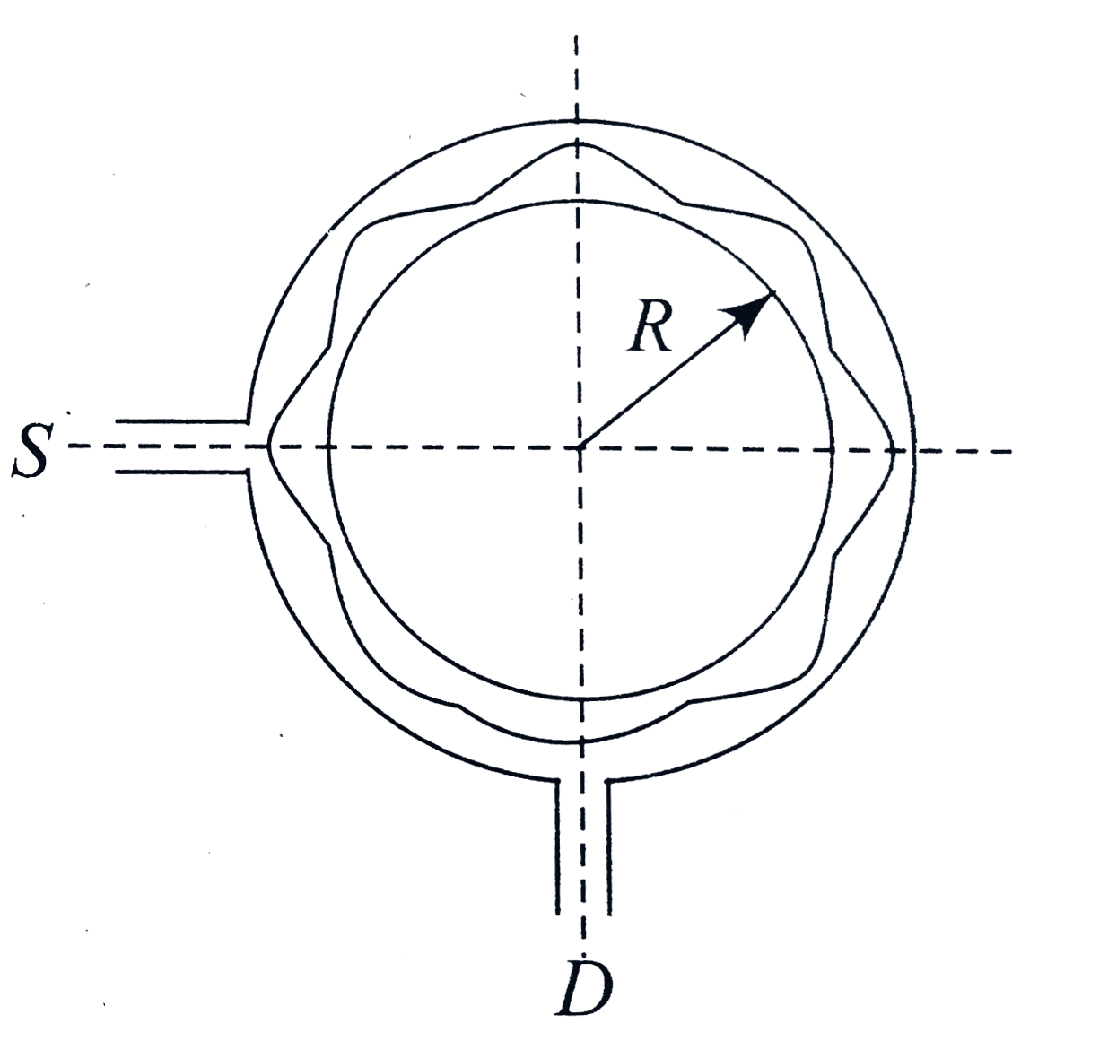
2. If a minima is formed at the detector, then the magnitude of wavelength `lambda` of the wave produced is given by
View SolutionA narrow tube is bent in the form of a circle of radius R, as shown in figure. Two small holes S and D are made in the tube at the position at right angle to each other. A source placed at S generates a wave of intensity `I_(0)` which two parts: one part travels along the longer path, while the other travels along the shorter path. Both the waves meet at point D where a detector is placed.
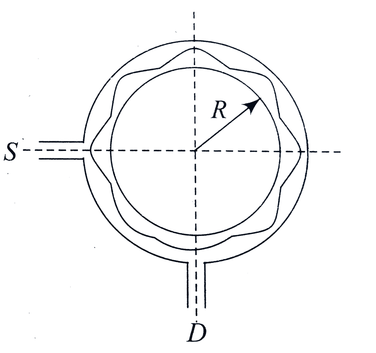
The maximum intensity produced at D is given by
View SolutionA thin film of a specific meterial can be used to decrease the intensity of reflected light. There is destrucive inteference of wave reflected from upper and lower surface of the film. These films are called non-reflecting or anti-reflecting coatings. The process of coating the lens or surface with non-reflecting film is called blooming as shown in figure The refracting index of coating `(n_(1))` is less than that of the glass `(n_(2))`.

4. If a light of wavelength `lambda` is incident normally and the thickness of film is t, then optical path difference between waves reflected from upper and lower surface of the film is
View SolutionA thin film of a specific meterial can be used to decrease the intensity of reflected light. There is destrucive inteference of wave reflected from upper and lower surface of the film. These films are called non-reflecting or anti-reflecting coatings. The process of coating the lens or surface with non-reflecting film is called blooming as shown in figure The refracting index of coating `(n_(1))` is less than that of the glass `(n_(2))`.

5. magnesium fluoride `(MgF_(2))` is generally use as anti-reflection coating. If refractive index of `MgF_(2)` is 1.25, then minimum thickness of film required is (Take `lambda = 500 nm`)
View SolutionA thin film of a specific meterial can be used to decrease the intensity of reflected light. There is destrucive inteference of wave reflected from upper and lower surface of the film. These films are called non-reflecting or anti-reflecting coatings. The process of coating the lens or surface with non-reflecting film is called blooming as shown in figure The refracting index of coating `(n_(1))` is less than that of the glass `(n_(2))`.

6. If the thickness of film in above question in not technologically possible to manufacture, then next thickness of film required is (approximately)
View SolutionIn a Young's double-slit experiment set up, source S of wavelength `6000 Å` illuminates two slits `S_(1)` and `S_(2)` which act two coherent sources. The sources S oscillates about its shown position according to the eqation `y = 1 + cos pi t`, where y is in millimeter and t in second.
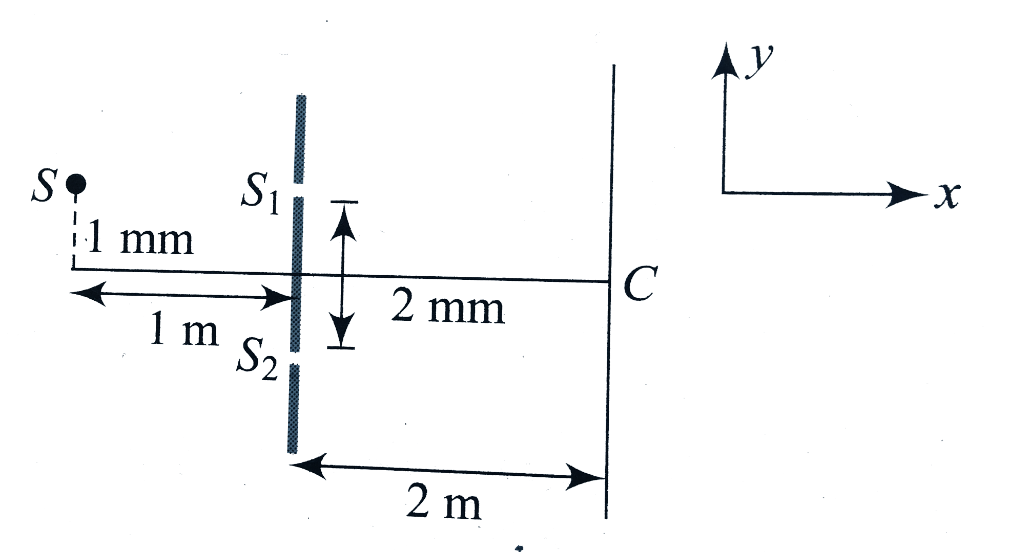
At `t = 0`, fringe width is `beta_(1)`, and at `t = 2` s, width of figure is `beta_(2)`. Then
View SolutionIn a Young's double-slit experiment set up, source S of wavelength `6000 Å` illuminates two slits `S_(1)` and `S_(2)` which act two coherent sources. The sources S oscillates about its shown position according to the eqation `y = 1 + cos pi t`, where y is in millimeter and t in second.
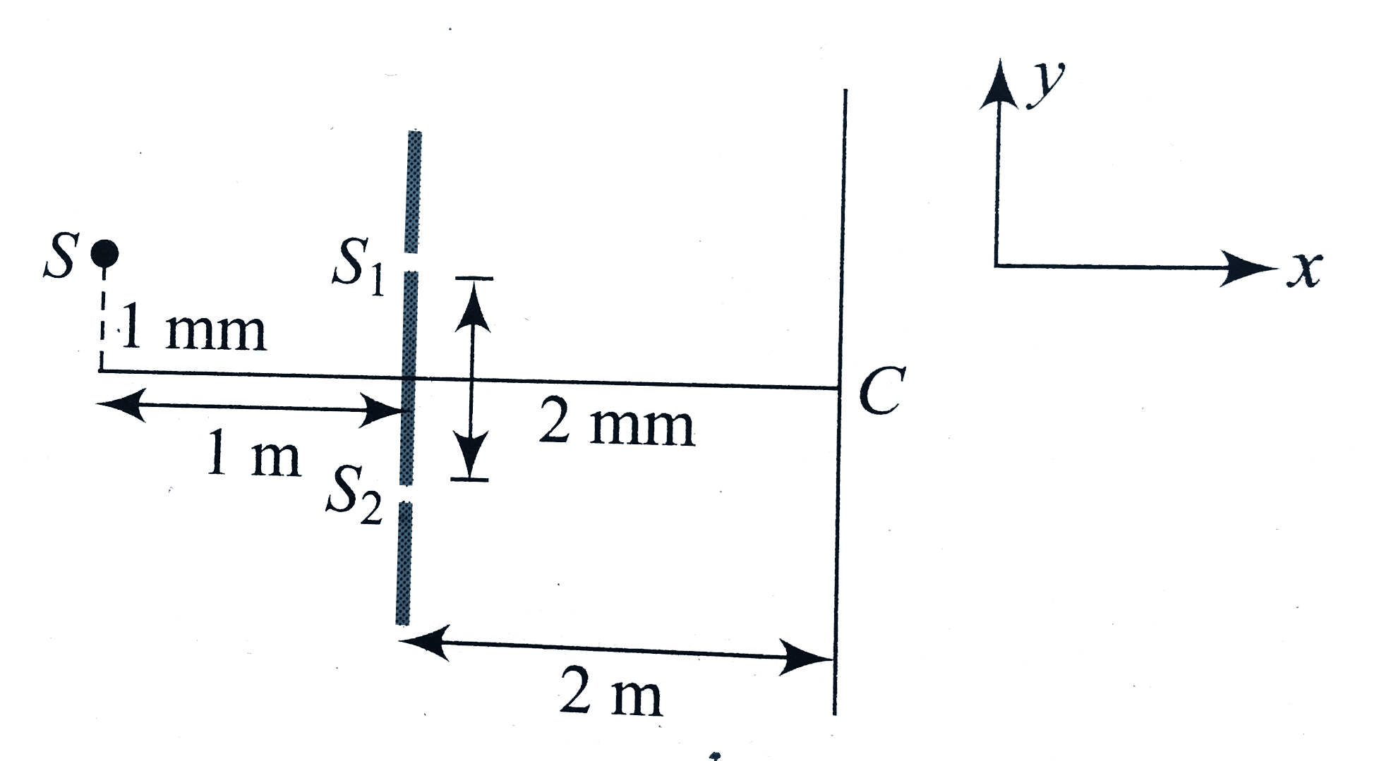
At `t = 2` s, the position of central maxima is
View SolutionIn a Young's double-slit experiment set up, source S of wavelength `6000 Å` illuminates two slits `S_(1)` and `S_(2)` which act two coherent sources. The sources S oscillates about its shown position according to the eqation `y = 1 + cos pi t`, where y is in millimeter and t in second.
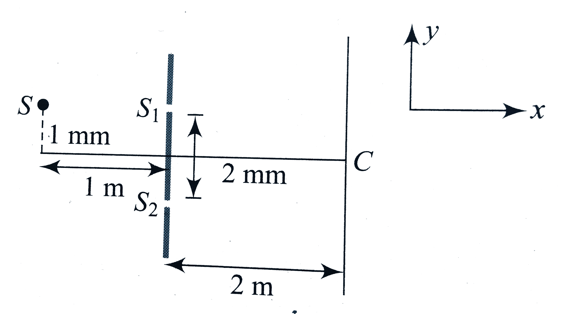
At `t = 1` s, a slab of thickness `2 xx 10^(-3) mm` an refractive index 1.5 is placed just in front of `S_(1)`. The central maximum is formed at
View SolutionTwo coherent sources emit light of wavelength `lambda`. Separation between them, `d = 4 lambda`.
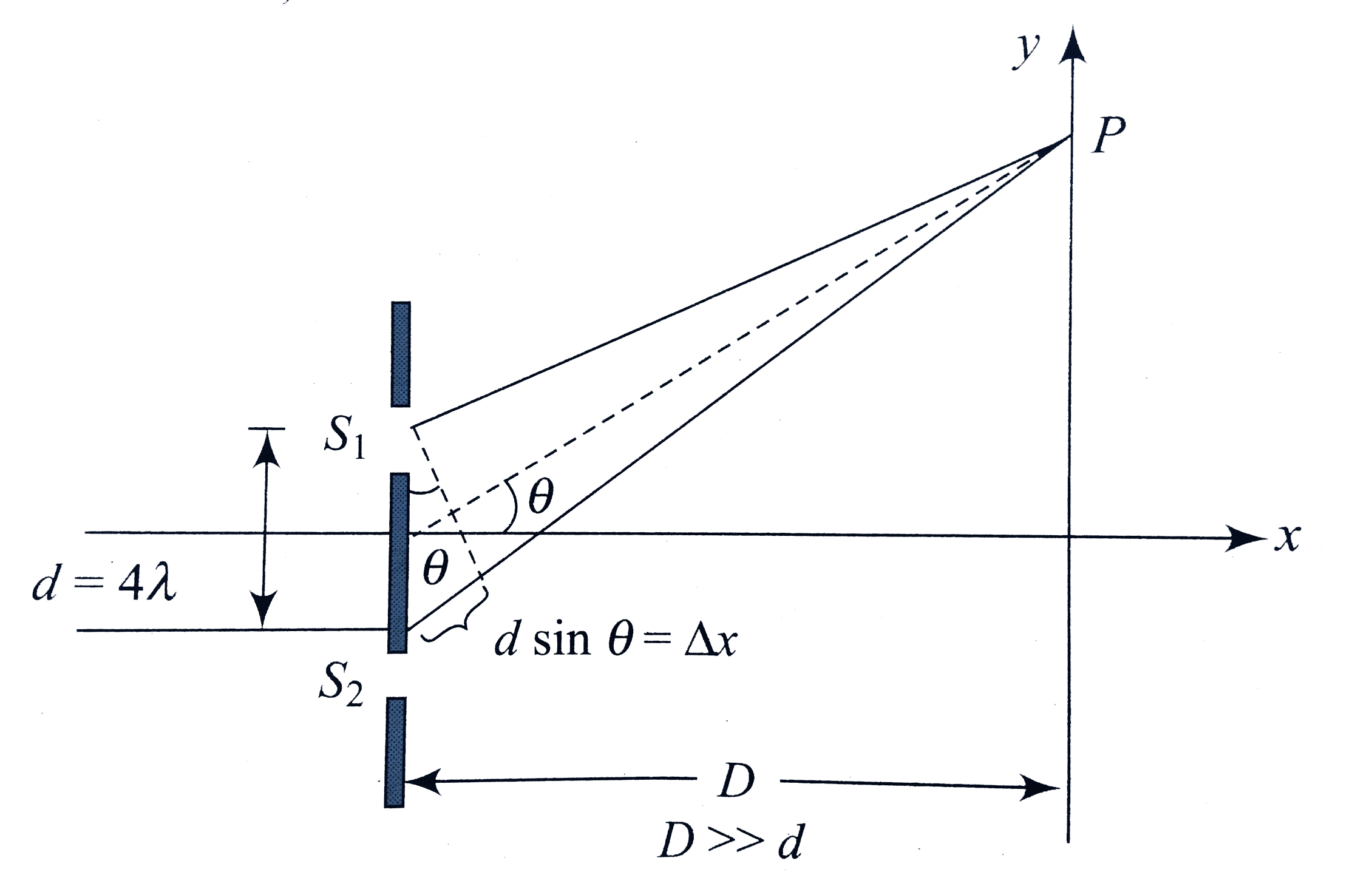
If a detector moves along the y-axis, what is the maximum number of minima observed?
View SolutionTwo coherent sources emit light of wavelength `lambda`. Separation between them, `d = 4 lambda`.
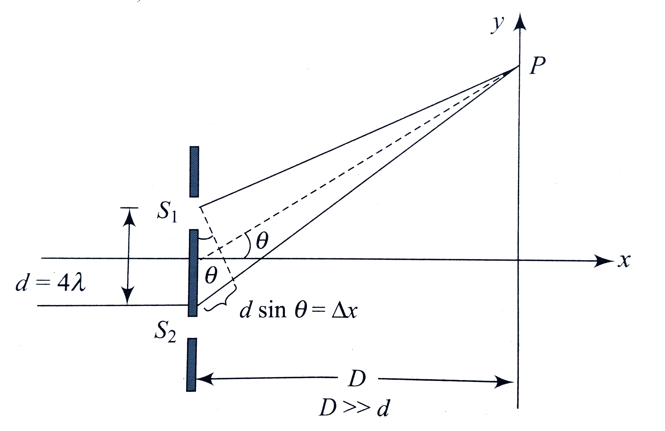
If a detector moves along the y-axis, what is the maximum number of minima observed?
If the detector moves along 'x-axis beginning from `S_(2)`, the maximum number of minima observed is
View SolutionIn YDSE, the sources is red ligth of wavelength `7 xx 10^(-7) m`. When a thin glass plate of refractive index 1.5 is put in the path of one of the interfering beams, the central bright fringe shifts by `10^(-3)` m to the position previously occupied by the 5th bright fringe.
What is the thickness of the plate?
View SolutionIn YDSE, the sources is red ligth of wavelength `7 xx 10^(-7) m`. When a thin glass plate of refractive index 1.5 is put in the path of one of the interfering beams, the central bright fringe shifts by `10^(-3)` m to the position previously occupied by the 5th bright fringe.
If the source is now changed to green light of wavelength `10^(-7)m`, the central fringe shifts to a position initially occupied by the sixth bright fringe due to red ligth. What will be refractive index of glass plate for the second ligth for changed source of ligth?
View SolutionIn YDSE, the sources is red ligth of wavelength `7 xx 10^(-7) m`. When a thin glass plate of refractive index 1.5 is put in the path of one of the interfering beams, the central bright fringe shifts by `10^(-3)` m to the position previously occupied by the 5th bright fringe.
Change is fringe width produced due to chanbe in wavelength is
View SolutionA coherent parallel beam of microwaves of wavelength `lambda = 0.5 mm` falls on aYoung's double- slit apparatus. The separation between the slits is 1.0 mm. The intensity of microwaves is measured on a screen placed parallel to the plane of the slits at a distance of 1.0 m from it as shown in figure
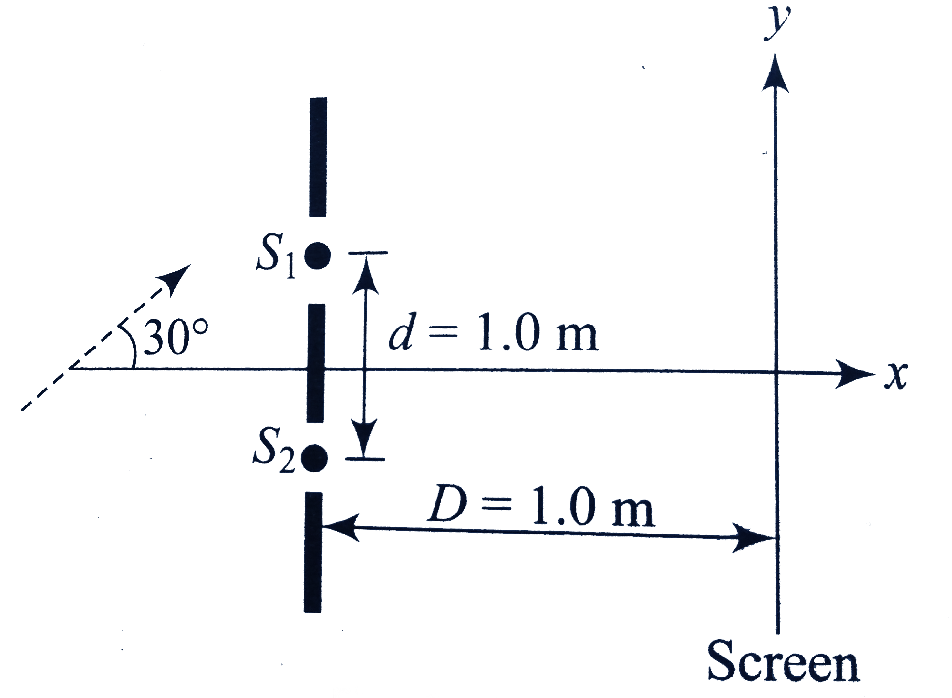
If the incient beam falls normally on the double-slit apparatus, find the order of the interference minima on the screen
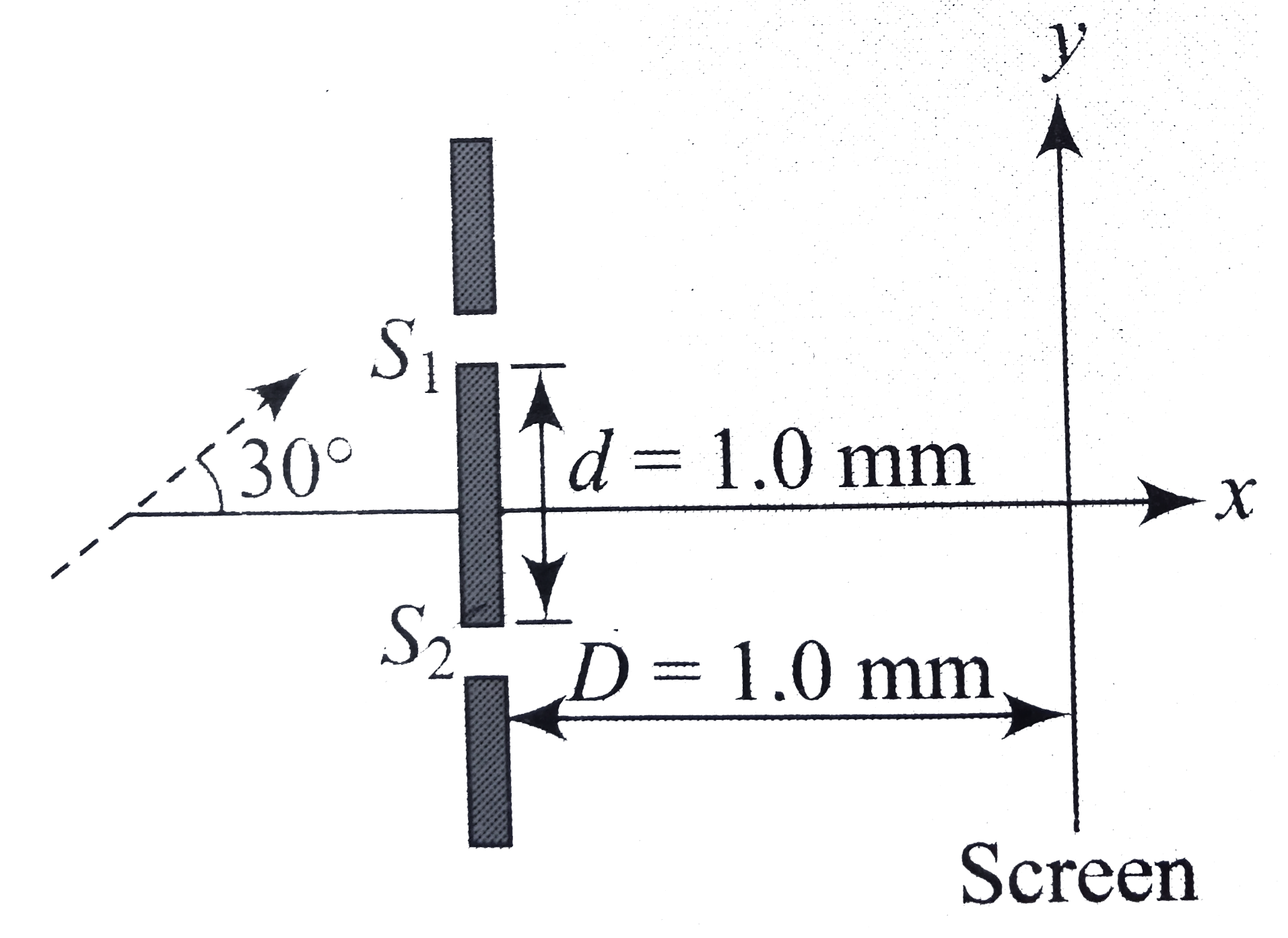
View SolutionA coherent parallel beam of microwaves of wavelength `lambda = 0.5 mm` falls on aYoung's double- slit apparatus. The separation between the slits is 1.0 mm. The intensity of microwaves is measured on a screen placed parallel to the plane of the slits at a distance of 1.0 m from it as shown in Fig. 2.42.
If the incident beam makes an angle or `30^(@)` with the x-axis (as in the dotted arrow shown in the figure), find the y-coordinates of the first minima on either side of the central maximum.
View SolutionA YDSE is performed in a medium of refractive index `4 // 3`, A light of 600 nm wavelength is falling on the slits having 0.45 nm separation . The lower slit `S_(2)` is covered b a thin glass plate of thickness 10.4 mm and refractive index 1.5. The interference pattern is observed on a screen placed 1.5 m from the slits as shown in figure. (All the wavelengths in this problem are for the given medium of refractive index `4 // 3`, ignore absorption.)
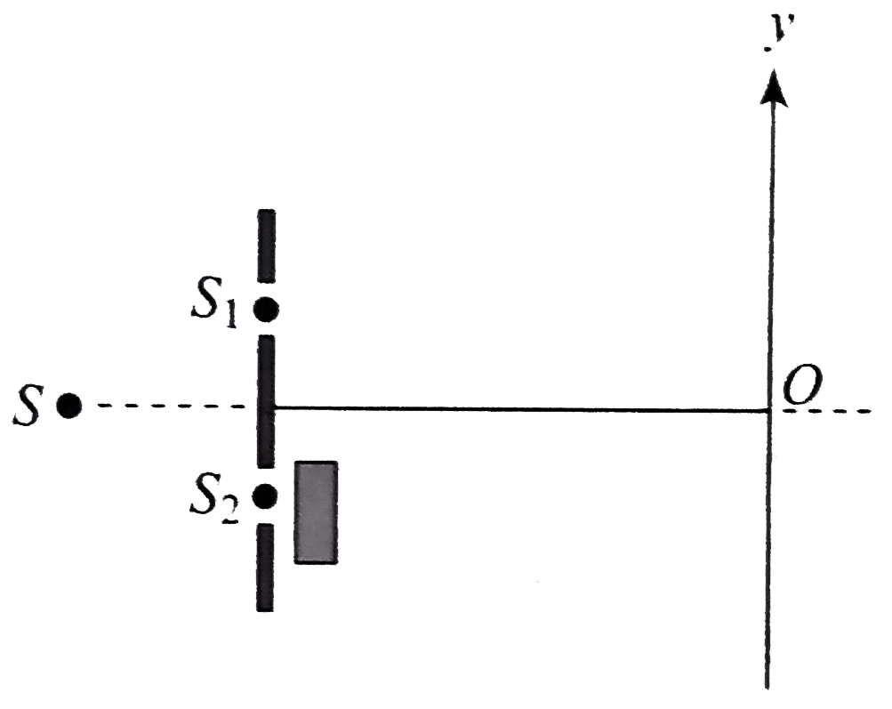
The location of the central maximum (bright fringe with zero path difference) on the y-axis will be
View SolutionA YDSE is performed in a medium of refractive index `4 // 3`, A light of 600 nm wavelength is falling on the slits having 0.45 nm separation . The lower slit `S_(2)` is covered b a thin glass plate of thickness 10.4 mm and refractive index 1.5. The interference pattern is observed on a screen placed 1.5 m from the slits as shown in figure. (All the wavelengths in this problem are for the given medium of refractive index `4 // 3`, ignore absorption.)
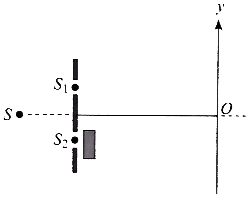
Find the light intensity at point O relative t maximum fringe intensity.
View SolutionA YDSE is performed in a medium of refractive index `4 // 3`, A light of 600 nm wavelength is falling on the slits having 0.45 nm separation . The lower slit `S_(2)` is covered b a thin glass plate of thickness 10.4 mm and refractive index 1.5. The interference pattern is observed on a screen placed 1.5 m from the slits as shown in figure. (All the wavelengths in this problem are for the given medium of refractive index `4 // 3`, ignore absorption.)
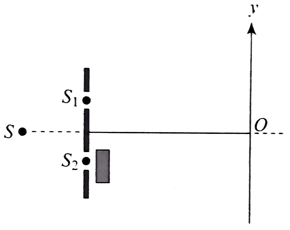
Now, if 600 nm, find the wavelength of the ligth that forms maximum exactly at point O.
View SolutionIn a YDSE perfromed with light of wavelength `600 Å`, the screen is placed 1 m from the slits. Fringes formed on the screen are observed by a student sitting close to the slits. The student's eye can distinguish two neighboring fringes. If they subtend an angle more then 1 minute of ace, then
In order to have the clear visibility of the fringe, the maximum distance that can be maintained between the slits is
View SolutionIn a YDSE perfromed with light of wavelength `600 Å`, the screen is placed 1 m from the slits. Fringes formed on the screen are observed by a student sitting close to the slits. The student's eye can distinguish two neighboring fringes. If they subtend an angle more then 1 minute of ace, then
Find the location of third bright fringe from center of the screen.
View SolutionIn a YDSE perfromed with light of wavelength `600 Å`, the screen is placed 1 m from the slits. Fringes formed on the screen are observed by a student sitting close to the slits. The student's eye can distinguish two neighboring fringes. If they subtend an angle more then 1 minute of ace, then
Under similar conditions or arrangement, what will be the position of fifth dark fringe from the center of screen?
View SolutionIn a modified YDSE, sources `S` is kept in front of slit `S_(1)`. Find the phase difference at point O that is equidistant from slits `S_(1)` and `S_(2)` and point P that is in front of slit `S_(1)` in the following situations.
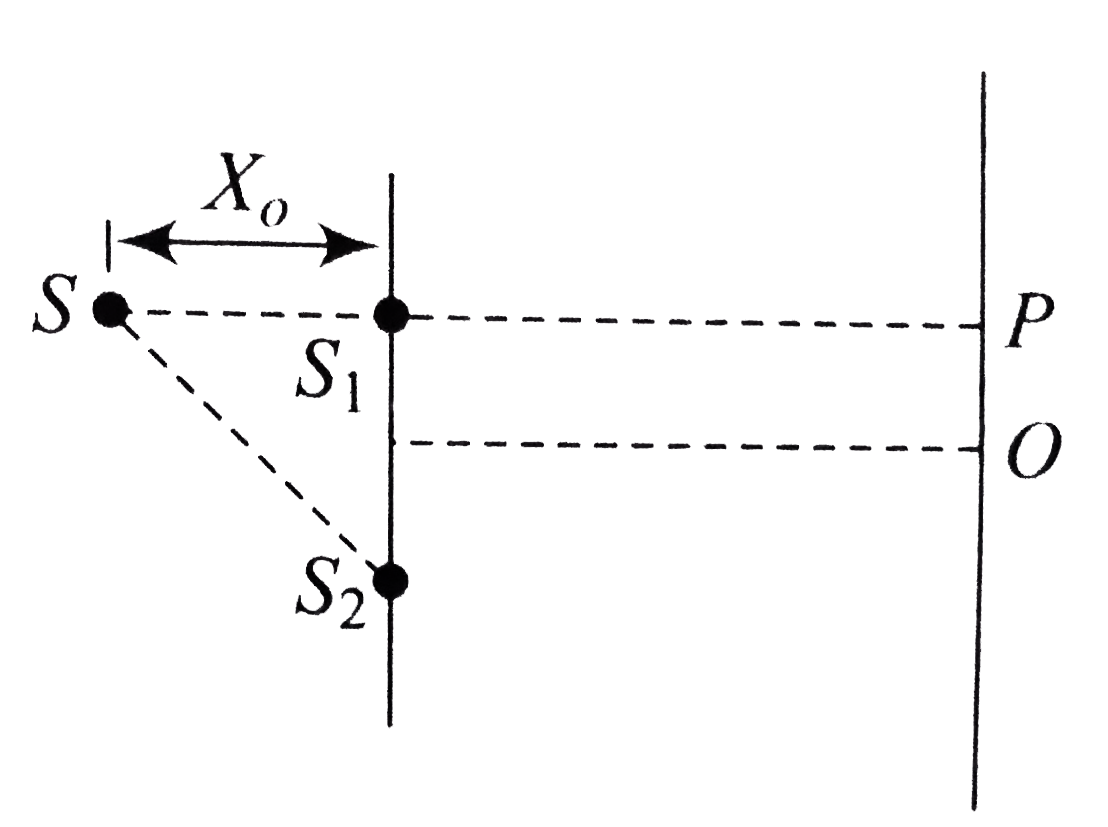
A liquid of refractive index `mu` is filled between the screen and slits.
View SolutionIn a midified YDESE, sources S is kept in front of slit `S_(1)`. Find the phase difference at point O that is equidistant from slits `S_(1)` and `S_(2)` and point P that is in front of slit `S_(1)` in the following situations. ltgt
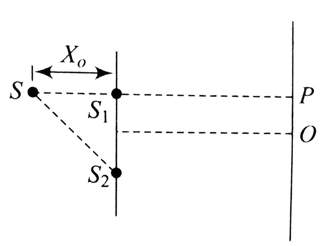
Liquid is filled between the slit and source S.
View SolutionIn a modified YDSE, the region between the screen and slits is immersed in a liquid whose refractive index varies with time as `mu_(1) = (5 // 2) - (T // 4)` until it reaches s steady state value of `5 // 4`. A glass plate of thickness 36 `mu m` and refractive index `3//2` is introduced in front of one of the slits.
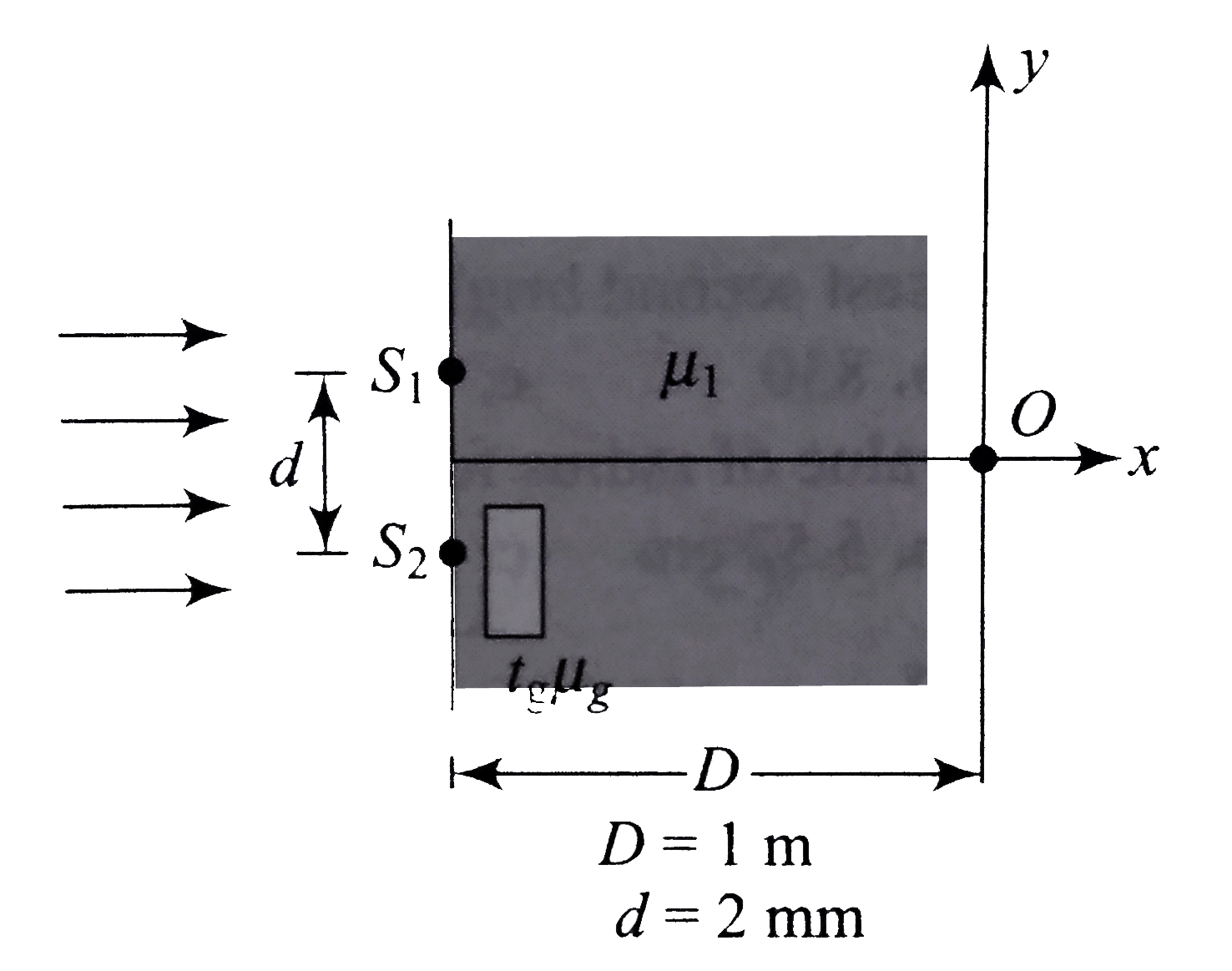
Find the time when central maxima is at point O. located symmetrically on the x-asix.
View SolutionIn a modified YDSE, the region between the screen and slits is immersed in a liquid whose refractive index varies with time as `mu_(1) = (5 // 2) - (T // 4)` until it reaches s steady state value of `5 // 4`. A glass plate of thickness 36 `mu m` and refractive index `3//2` is introduced in front of one of the slits.

What is the speed of the central maxima when it is at
View SolutionIn a YDSE using monochromatic visible light, the distance between the plate of slits and the screen is 1.7 m. At point P on the screen which is directly in front of the upper slit, maximum path is observed. Now, the screen is moved 50 cm closer to the plane of slits. Point P now lies between third and fouth minima above the central maxima and the intensity at P in one-fourth of the maxima intensity on the screen.
Find the value of n.
View SolutionIn a YDSE using monochromatic visible light, the distance between the plate of slits and the screen is 1.7 m. At point P on the screen which is directly in front of the upper slit, maximum path is observed. Now, the screen is moved 50 cm closer to the plane of slits. Point P now lies between third and fouth minima above the central maxima and the intensity at P in one-fourth of the maxima intensity on the screen. ltbr. Find the wavelength of light if the separation of slits is 2 mm.
View SolutionIn figure, a screen is placed normaol to the line joining the two point coherent sources `S_(1)` and `S_(2)`. The interference pattern consists of concentric circles.
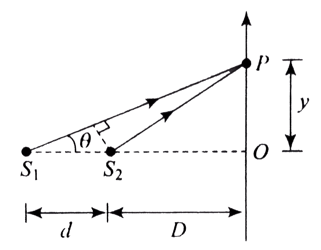
Find the radius of the nth bright ring
View SolutionIn figure, a screen is placed normal to the line joining the two point coherent sources `S_(1)` and `S_(2)`. The interference pattern consists of concentric circles.
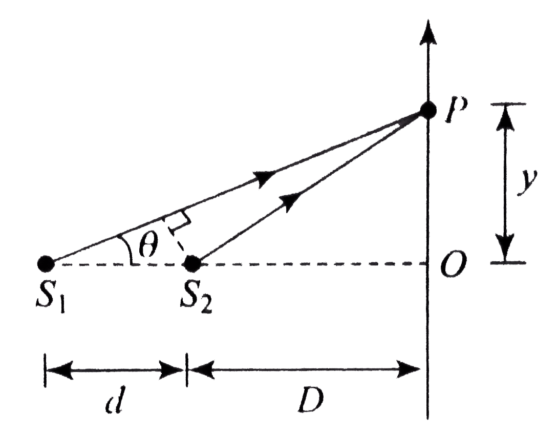
If `d = 0.5 mm, lambda = 5000 Å` and `D - 10 cm`, find the value of n for the closest second bright ring.
View SolutionIn figure, a screen is placed normaol to the line joining the two point coherent sources `S_(1)` and `S_(2)`. The interference pattern consists of concentric circles.
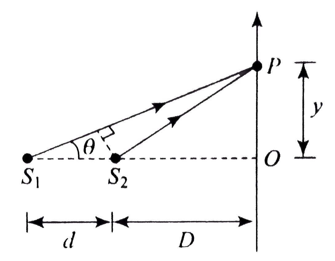
Also, find the value of radius for this ring.
View SolutionIn the arrangement shown in figure, light of wavelength `6000 Å` is incident on slits `S_(1)` and `S_(2)` have been opened such that `S_(3)` is the position of first maximum above the central maximum and `S_(4)` is the closest position where intensity is same as that of the ligth used, below the central maximum Point O is equidistant from `S_(1)` and `S_(2)` and O' is equidistant from `S_(3)` and `S_(4)`. Then intensity of inciden light is `I_(0)`
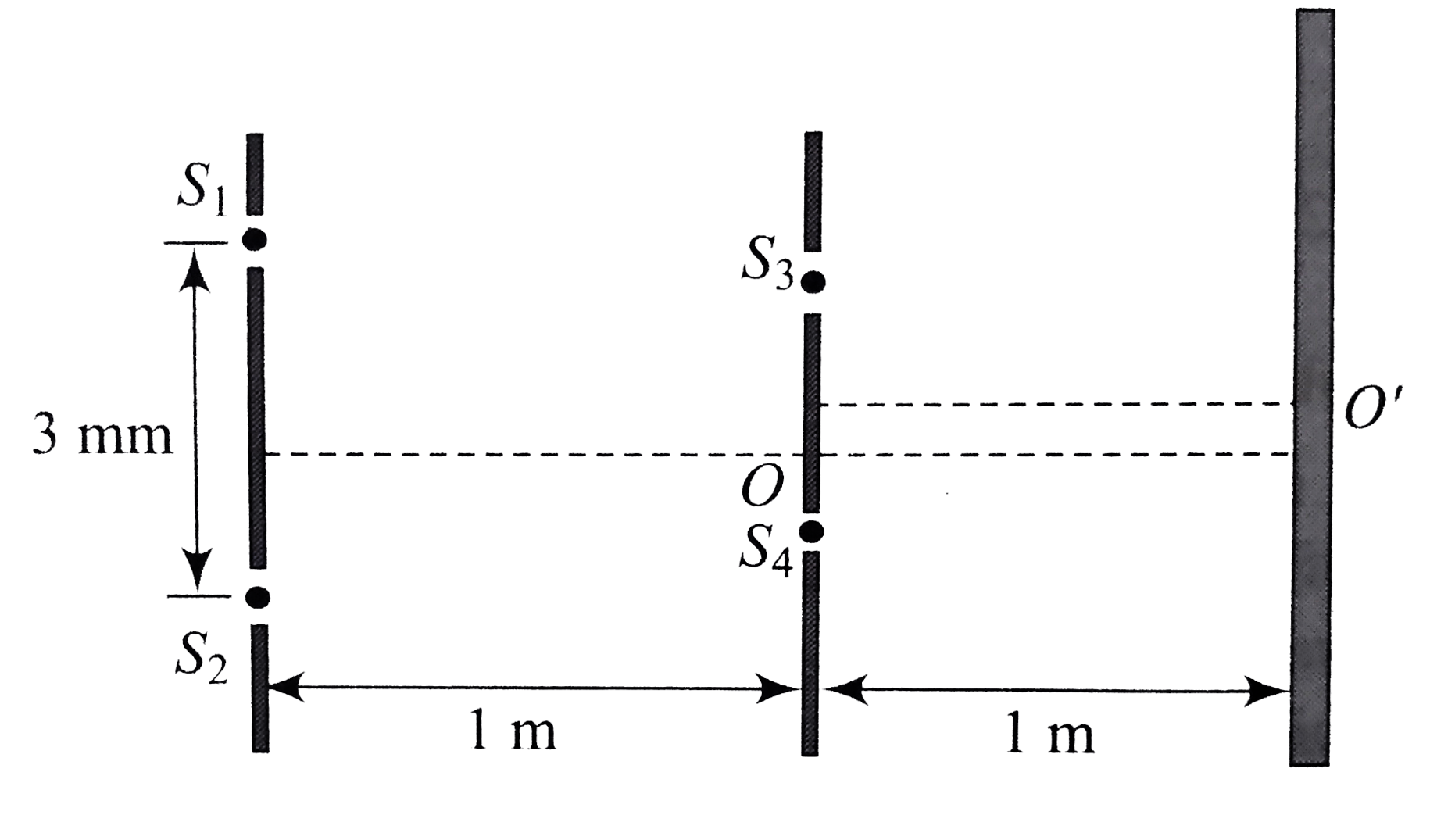
Find the intensity at O' (on the screen).
View SolutionIn the arrangement shown in figure, light of wavelength `6000 Å` is incident on slits `S_(1)` and `S_(2)` have been opened such that `S_(3)` is the position of first maximum above the central maximum and `S_(4)` is the closest position where intensity is same as that of the ligth used, below the central maximum Point O is equidistant from `S_(1)` and `S_(2)` and O' is equidistant from `S_(3)` and `S_(4)`. Then intensity of inciden light is `I_(0)`
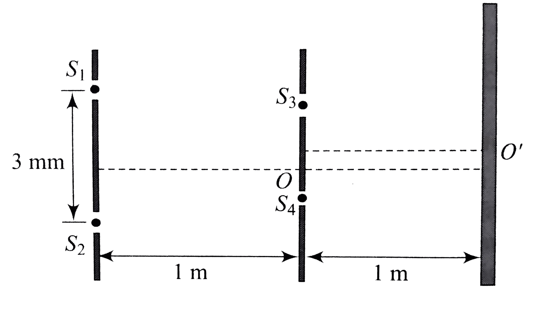
Find the intensity of the brightest fringe.
View SolutionA lens of focal length f is cut along the diameter into two identical halevs. In this process, a layer of the lens t in thickness is lost, then the halves are put together to form a composite lens. In between the focal plane and the composite lens, a narrow slit is placed near the focal plane. The slit is emitting monochromatic `lambda`. Behind the lens, a screen is located at a distance L front it.
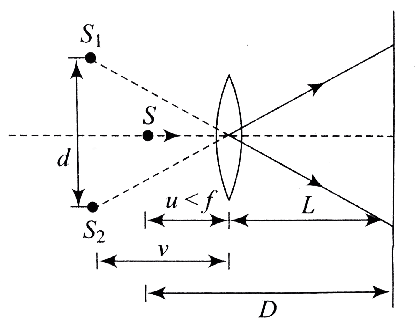
Find the fringe width for the pattern obtained under given arrangement on the screen.
View SolutionA lens of focal length f is cut along the diameter into two identical halevs. In this process, a layer of the lens t in thickness is lost, then the halves are put together to form a composite lens. In between the focal plane and the composite lens, a narrow slit is placed near the focal plane. The slit is emitting monochromatic `lambda`. Behind the lens, a screen is located at a distance L front it.
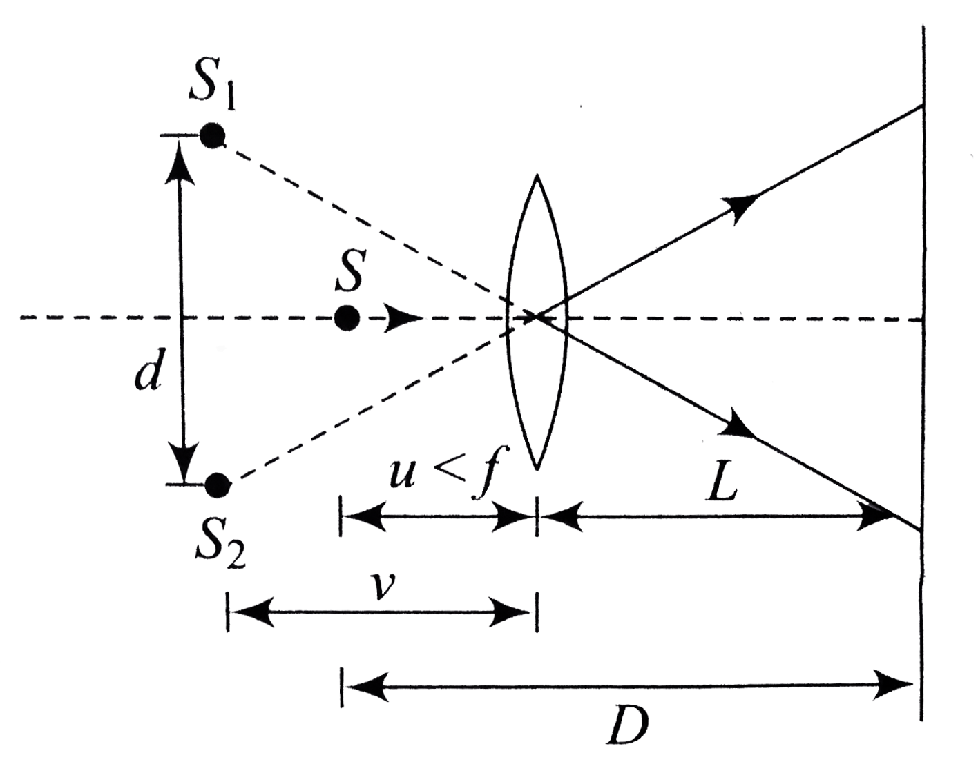
The expression for the number of visible maxima which are obtained through above said arrangement will turn out to be
View SolutionIn the arrangment shown in fin.
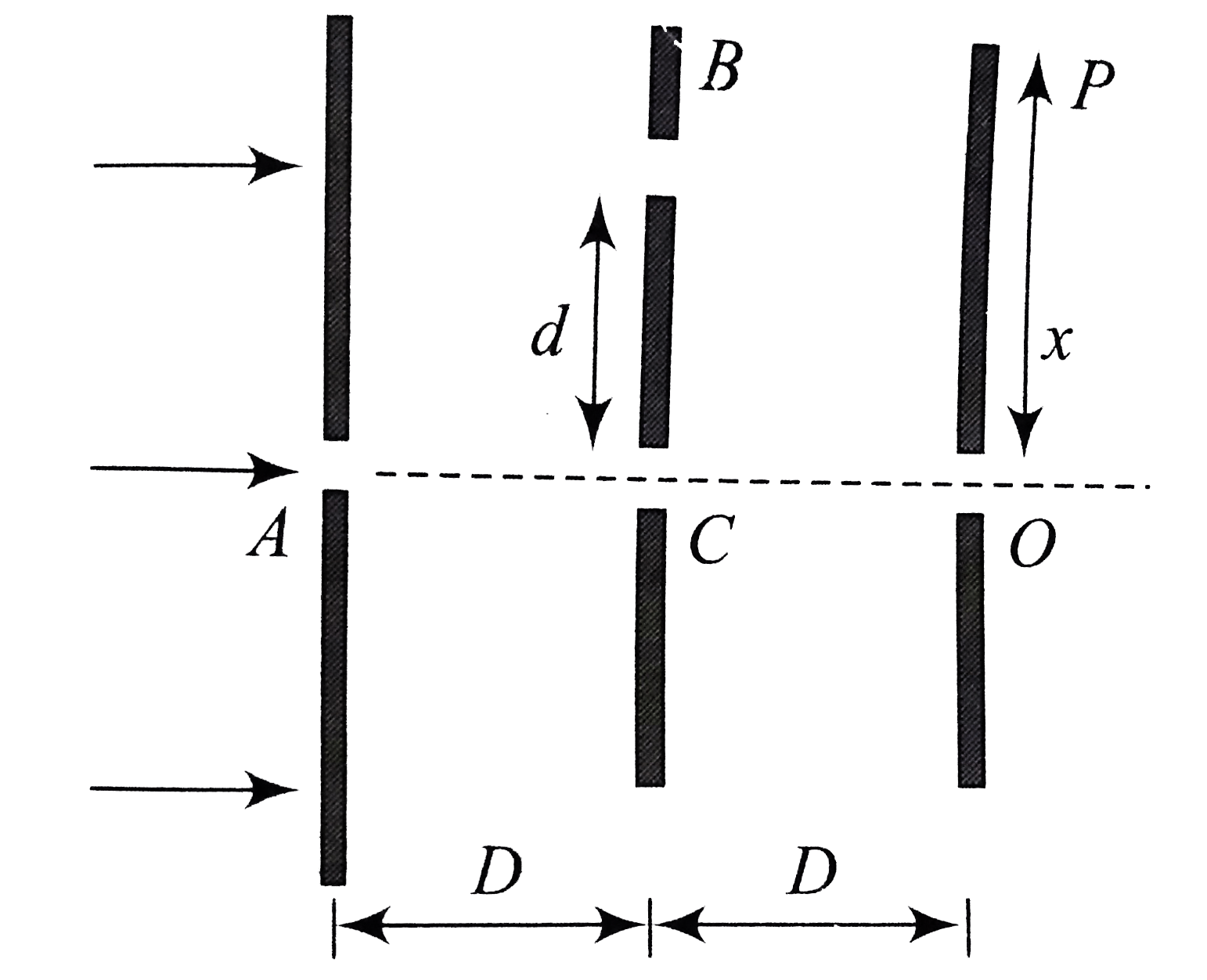
For what minimum value of d is there a dark bant at point O on the screen?
View SolutionIn the arrangment shown in fin.
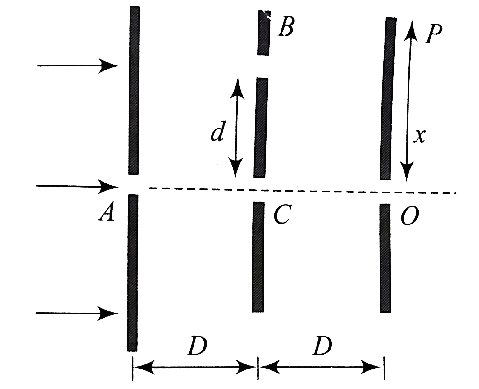
Find the distance x at which the next fringe is formed.
View SolutionIn the arrangment shown in fin.
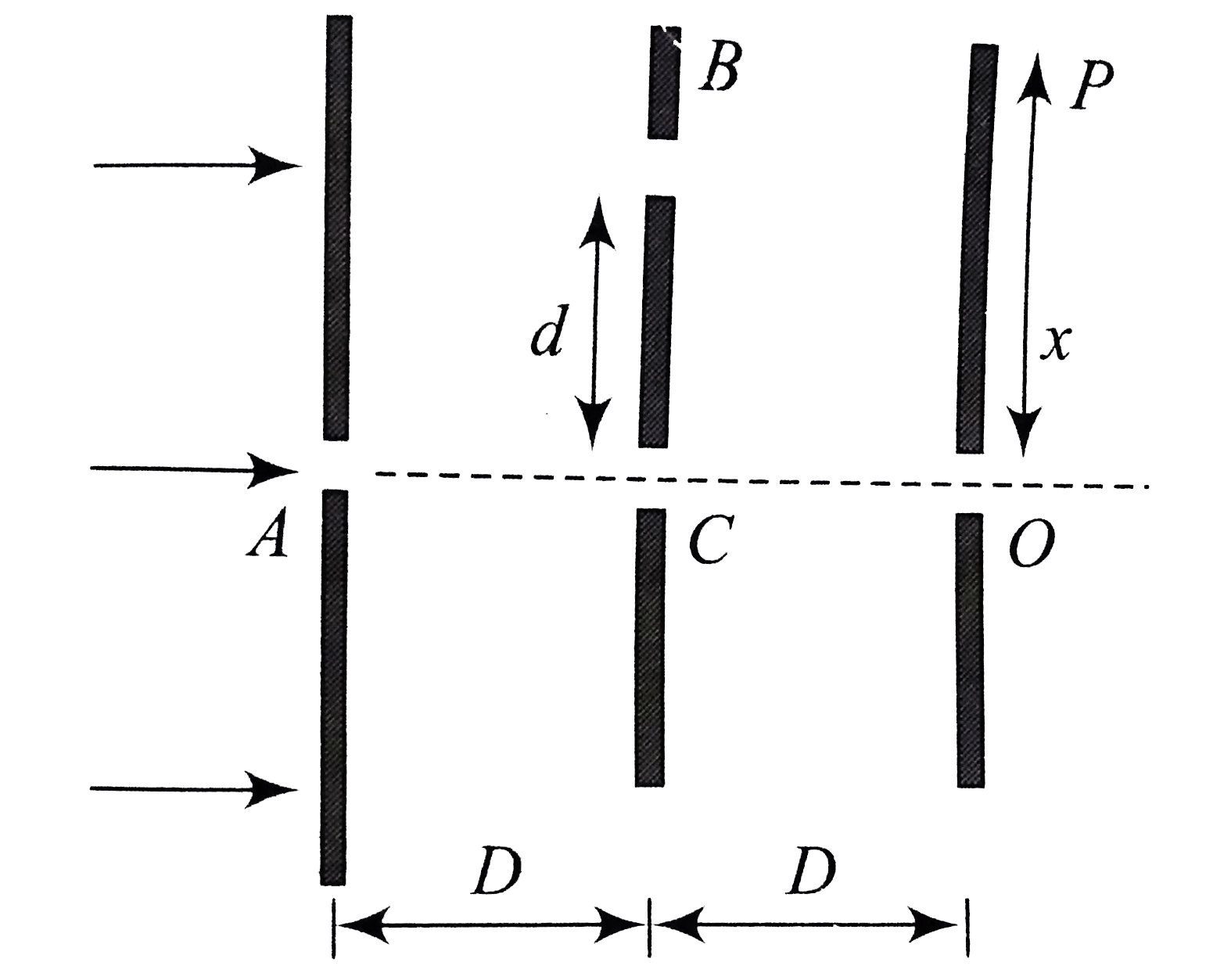 Find the fringe width.
View SolutionConsider the situation shown in fig. The two slits `S_(1)` and `S_(2)` placed symmetrically around the central line are illuminated by monochromatic light of wavelength `lambda`. The separation between the slit is d. The ligth transmitted by the slits falls on a screen `S_(0)` placed at a distance D form the slits. The slit `S_(3)` is at the central line and the slit `S_(4)` is at a distance z from `S_(3)` Another screen `S_(c)` is placed a further distance D away from `S_(c)` Find the ratio of the maximum to minimum intensity observed on `S_(c)`
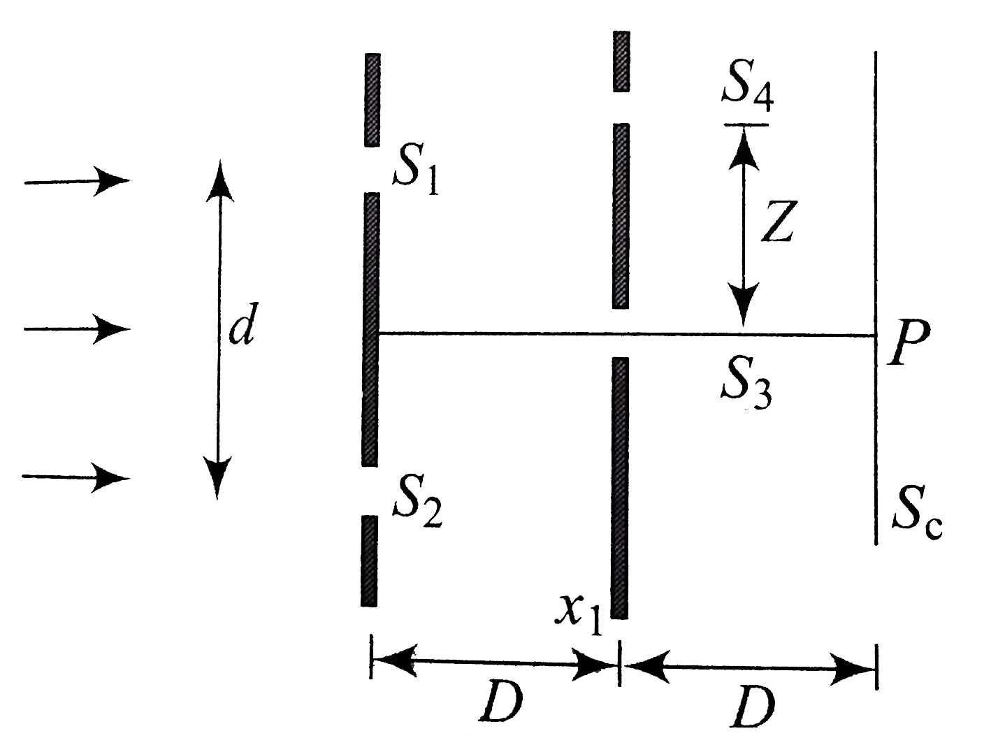
If `z = (lambda D)/(2 d)`
View SolutionConsider the situation shown in fig. The two slits `S_(1)` and `S_(2)` placed symmetrically around the central line are illuminated by monochromatic light of wavelength `lambda`. The separation between the slit is d. The ligth transmitted by the slits falls on a screen `S_(0)` placed at a distance D form the slits. The slit `S_(3)` is at the central line and the slit `S_(4)` is at a distance z from `S_(3)` Another screen `S_(c)` is placed a further distance D away from `S_(c)` Find the ratio of the maximum to minimum intensity observed on `S_(c)`
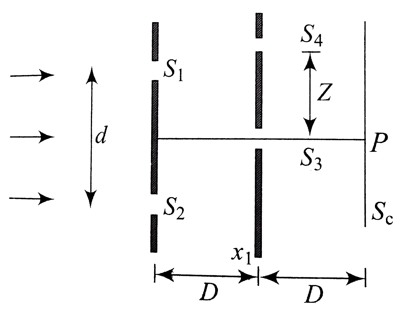
If `z = (lambda D)/(d)`
View SolutionConsider the situation shown in fig. The two slits `S_(1)` and `S_(2)` placed symmetrically around the central line are illuminated by monochromatic light of wavelength `lambda`. The separation between the slit is d. The ligth transmitted by the slits falls on a screen `S_(0)` placed at a distance D form the slits. The slit `S_(3)` is at the central line and the slit `S_(4)` is at a distance z from `S_(3)` Another screen `S_(c)` is placed a further distance D away from `S_(c)` Find the ratio of the maximum to minimum intensity observed on `S_(c)`
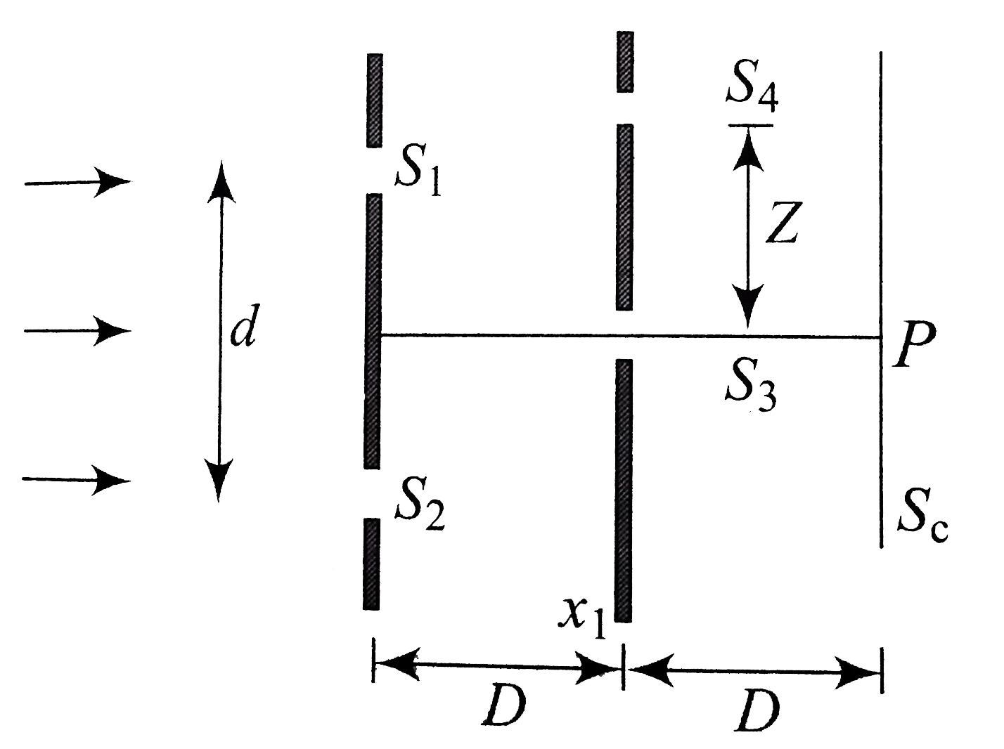
If `z = (lambda D)/(4 d)`
View SolutionThe arrangement for a mirror experiment is shown in figure. S is a point source of frequency `6xx10^(14)Hz`. D and C represent the two ends of a mirror placed horizontally and LOM represents the screen.

Determine the width of the region where the fringes will be visible
View SolutionThe arrangement for a mirror experiment is shown in figure. S is a point source of frequency `6xx10^(14)Hz`. D and C represent the two ends of a mirror placed horizontally and LOM represents the screen.

Find the fringe width of the fringe pattern ?
View SolutionThe arrangement for a mirror experiment is shown in figure. S is a point source of frequency `6xx10^(14)Hz`. D and C represent the two ends of a mirror placed horizontally and LOM represents the screen.

Calculate the number of fringes
View SolutionYoung's double-slit experiment setup with ligth of wavelength `lambda = 6000 Å`, distance between two slit in 2 mm and distance between the plane of slits and the screen. Is 2 m. The slits are of equal intensity. When a sheet of glass of refractive index 1.5 (which permtis only a fraction `eta` of the incident light to pass through) and thickness `8000 Å` is placed in front of the lower slit, it is observed that the intensity at a point P, 0.15 mm above the central maxima, does not change.
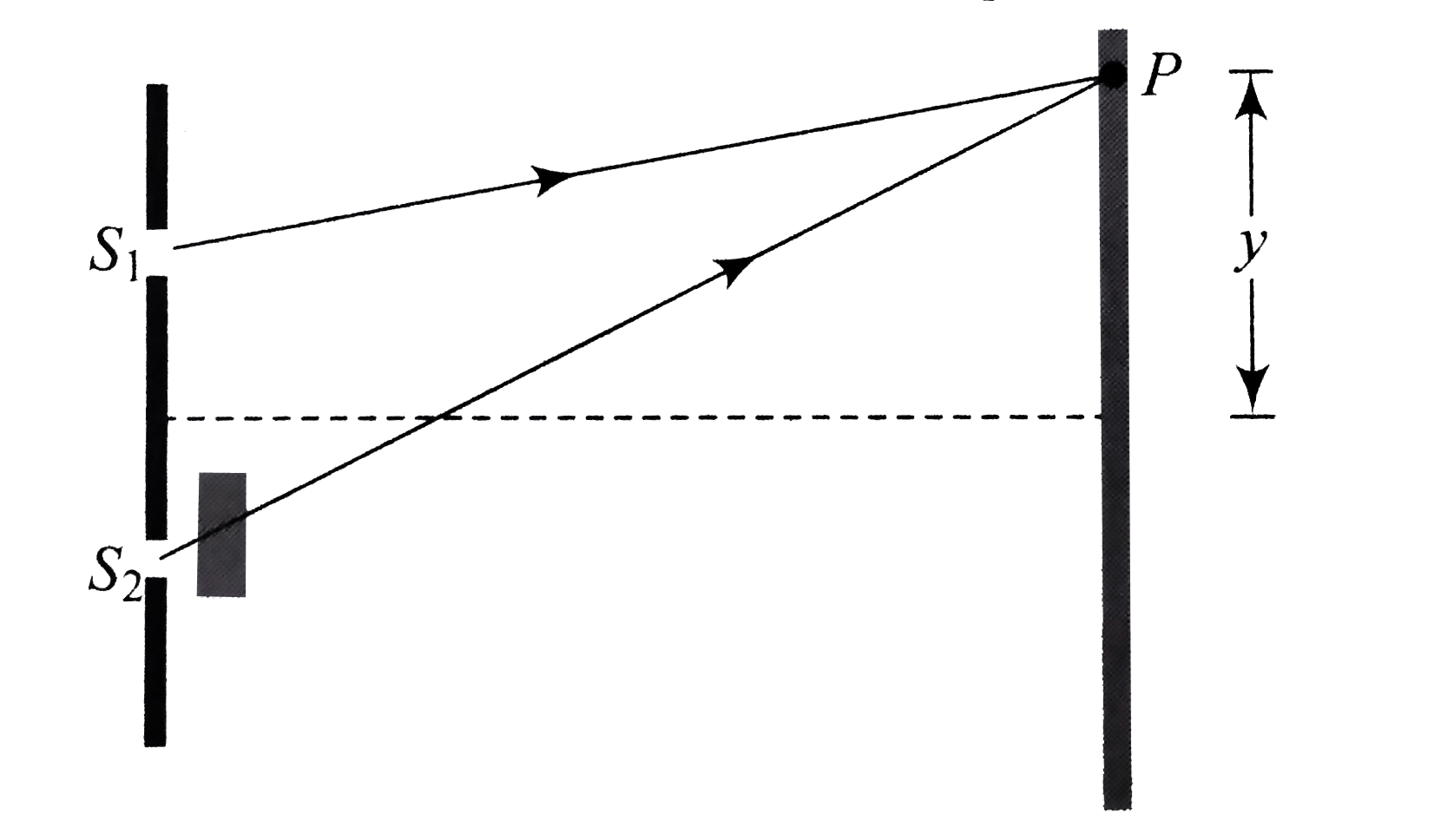
The phase difference at point P without inserting the slab is
View SolutionYoung's double-slit experiment setup with ligth of wavelength `lambda = 6000 Å`, distance between two slit in 2 mm and distance between the plane of slits and the screen. Is 2 m. The slits are of equal intensity. When a sheet of glass of refractive index 1.5 (which permtis only a fraction `eta` of the incident light to pass through) and thickness `8000 Å` is placed in front of the lower slit, it is observed that the intensity at a point P, 0.15 mm above the central maxima, does not change.
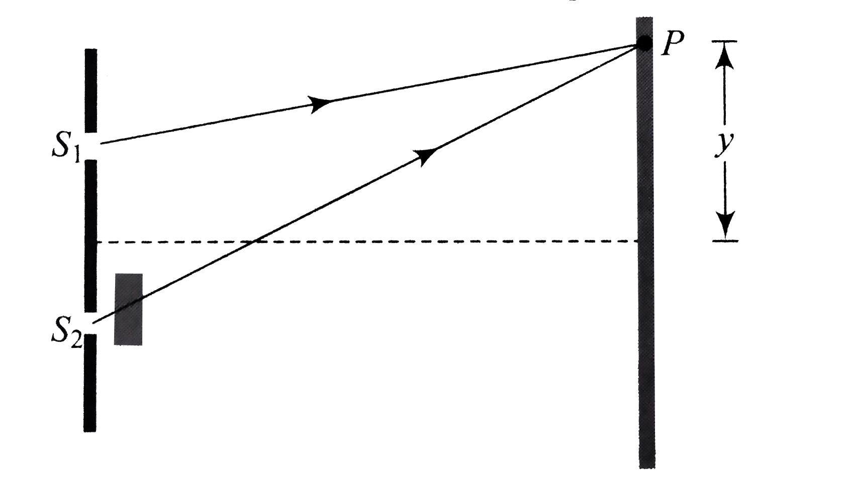
Intensity at point P is
View SolutionYoung's double-slit experiment setup with ligth of wavelength `lambda = 6000 Å`, distance between two slit in 2 mm and distance between the plane of slits and the screen. Is 2 m. The slits are of equal intensity. When a sheet of glass of refractive index 1.5 (which permtis only a fraction `eta` of the incident light to pass through) and thickness `8000 Å` is placed in front of the lower slit, it is observed that the intensity at a point P, 0.15 mm above the central maxima, does not change.
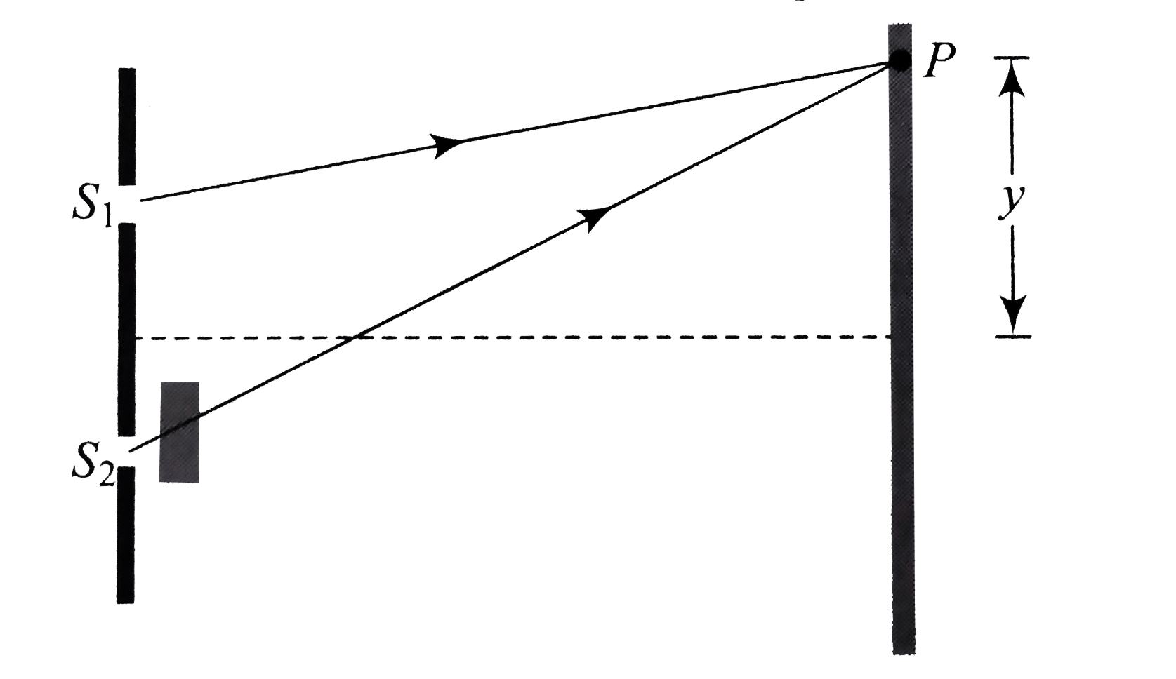
The value of `eta` is
View SolutionAn interference is observed due to two coherent sources `S_(1)` placed at origin and `S_(2)` placed at (0, 3l, 0). Here, `lambda` is the wavelength of the sources. Both sources are having equal intensity `I_(0)`. A detector D is moved along the positive x-axix.
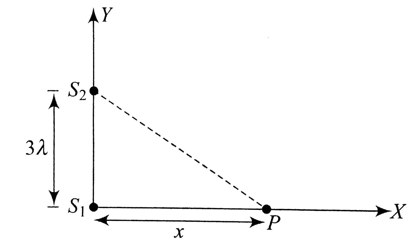
Total number of black points observed by the observer on positive x-axis is
View SolutionAn interference is observed due to two coherent sources `S_(1)` placed at origin and `S_(2)` placed at (0, 3l, 0). Here, `lambda` is the wavelength of the sources. Both sources are having equal intensity `I_(0)`. A detector D is moved along the positive x-axix.
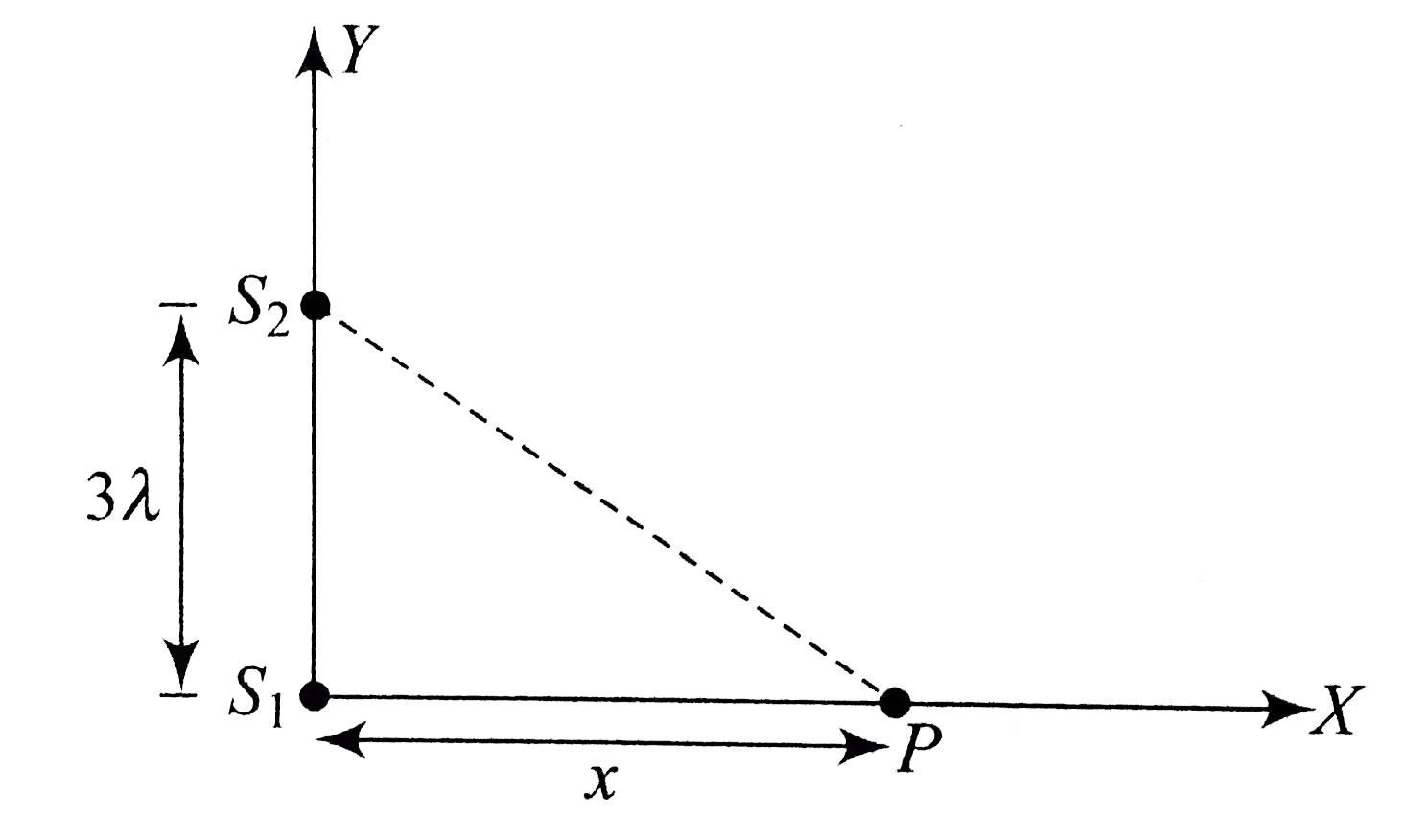
Find x-coordinates on the x-axis (exchange `x = 0` and `x = OO`).
View Solution_E01_080_Q01.png)
The figure shows the interfernece pattern obtained in double slit experiment using light of wavelength 600 nm.
Q. The third order bright fringe is
View Solution_E01_081_Q01.png)
The figure shows the interfernece pattern obtained in double slit experiment using light of wavelength 600 nm.
Q. Which fringe results from a phase difference of `4pi` between the light waves incidenting from two slits?
View Solution_E01_082_Q01.png)
The figure shows the interfernece pattern obtained in double slit experiment using light of wavelength 600 nm.
Q. Let `DeltaX_(A)` and `DeltaX_(C)` represent path differences between waves interering at 1 and 3 respectively then `(|DeltaX_(C)|-(|DeltaX_(A)|)` is equal to
View SolutionThis interference film is used to measure the thickness of slides, paper, etc. The arrangement is as shown in fig. For the sake of clarity, the two strips are shown thick. Consider the wedge formed in between strips 1 and 2. If the interference pattern because of the two waves reflected from wedge surface is observed, then from the observed data we can compute thickness of paper, refractive index of the medium filled in wedge, number of bonds formed, etc.
Considre the strips to be thick as compared to wavelength of ligth and light is incident normally.
Neglect the effect due to reflection from top surface of strip 1 and bottom surface of strip 2. Take `L = 5 cm` and `lambda_(air) = 40 nm`.
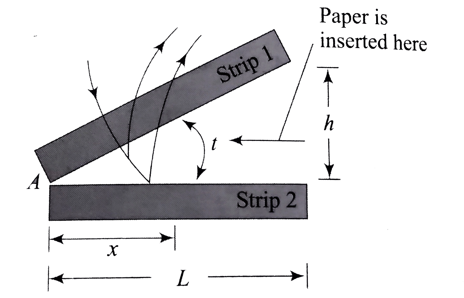
Consider an air wedge formed by two glass plates. having refractive index 1.5 by placing a piece of paper of thickness 20 mm. Determine the number of dark bands formed.
View SolutionThis interference film is used to measure the thickness of slides, paper, etc. The arrangement is as shown in fig. For the sake of clarity, the two strips are shown thick. Consider the wedge formed in between strips 1 and 2. If the interference pattern because of the two waves reflected from wedge surface is observed, then from the observed data we can compute thickness of paper, refractive index of the medium filled in wedge, number of bonds formed, etc.
Considre the strips to be thick as compared to wavelength of ligth and light is incident normally.
Neglect the effect due to reflection from top surface of strip 1 and bottom surface of strip 2. Take `L = 5 cm` and `lambda_(air) = 40 nm`.
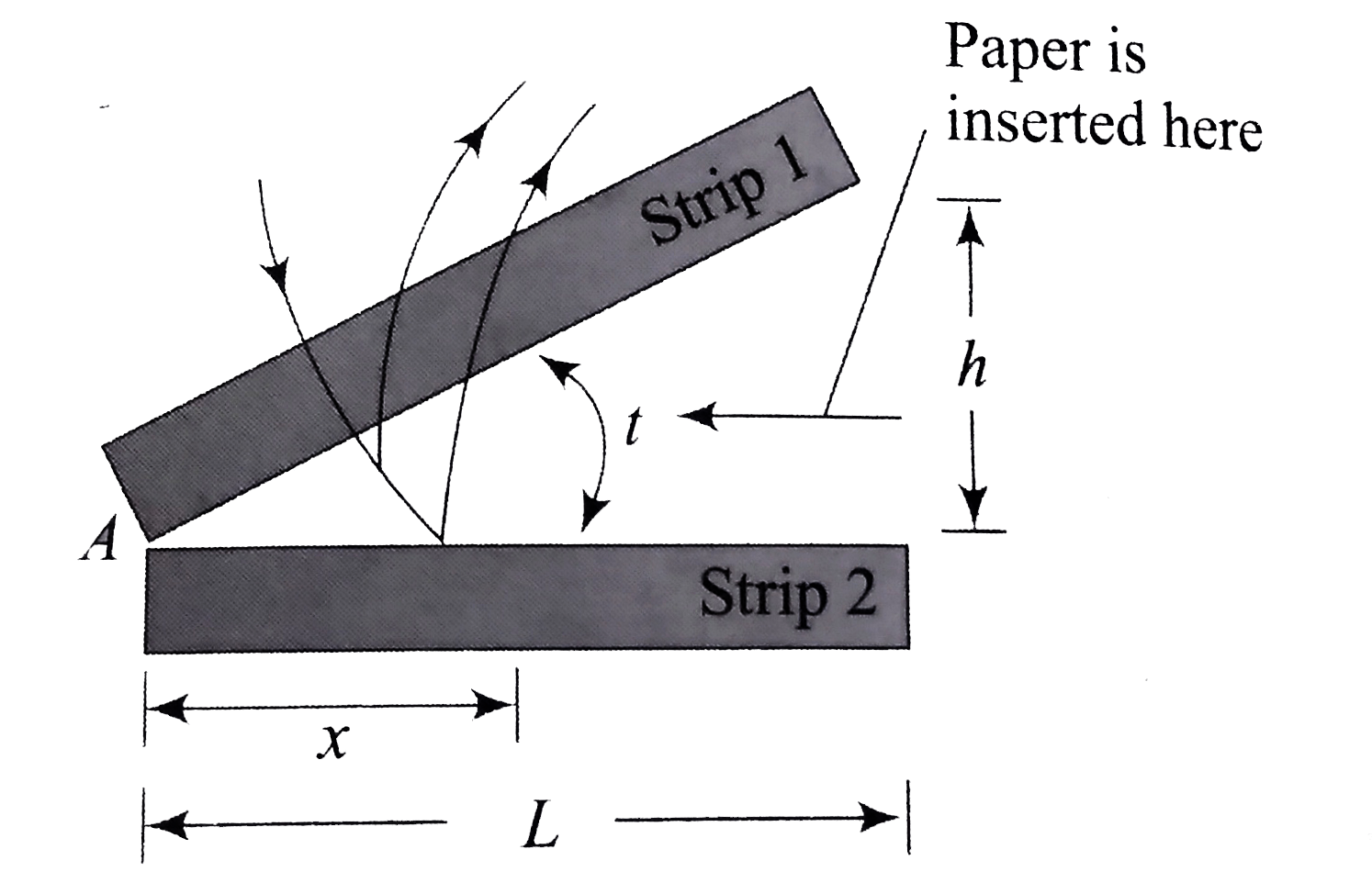
For strip 1 refractive index is 1.34 abd for strip 2 refractive index is 1.6 The wedge. is filled with a medium having refractive index 1.5. Then
View SolutionThis interference film is used to measure the thickness of slides, paper, etc. The arrangement is as shown in fig. For the sake of clarity, the two strips are shown thick. Consider the wedge formed in between strips 1 and 2. If the interference pattern because of the two waves reflected from wedge surface is observed, then from the observed data we can compute thickness of paper, refractive index of the medium filled in wedge, number of bonds formed, etc.
Considre the strips to be thick as compared to wavelength of ligth and light is incident normally.
Neglect the effect due to reflection from top surface of strip 1 and bottom surface of strip 2. Take `L = 5 cm` and `lambda_("air") = 40 nm`.
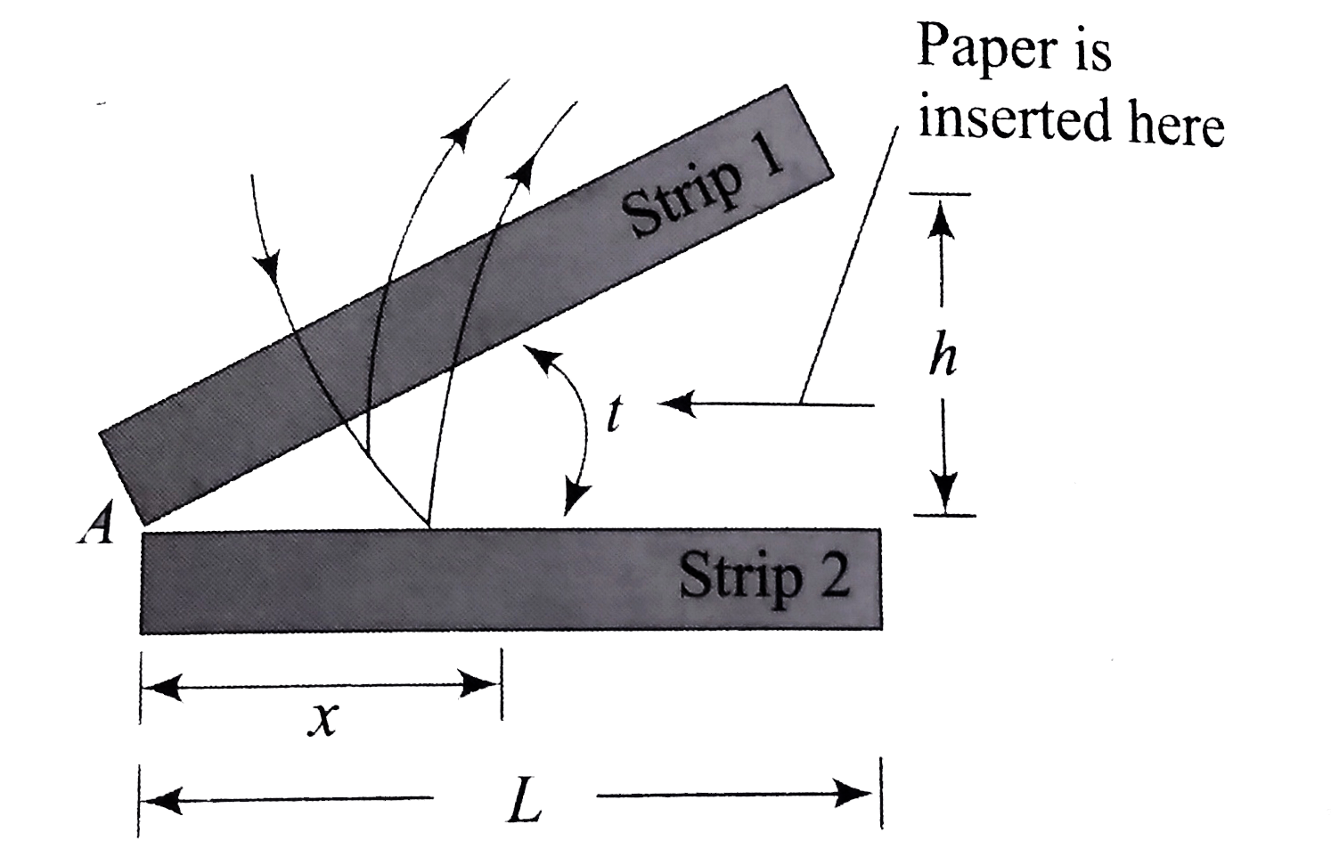
In question 53, if air wedge has been filled with a medium having refractive index 1.3 then find the number of bright bands.
View SolutionThis interference film is used to measure the thickness of slides, paper, etc. The arrangement is as shown in fig. For the sake of clarity, the two strips are shown thick. Consider the wedge formed in between strips 1 and 2. If the interference pattern because of the two waves reflected from wedge surface is observed, then from the observed data we can compute thickness of paper, refractive index of the medium filled in wedge, number of bonds formed, etc.
Considre the strips to be thick as compared to wavelength of ligth and light is incident normally.
Neglect the effect due to reflection from top surface of strip 1 and bottom surface of strip 2. Take `L = 5 cm` and `lambda_(air) = 40 nm`.
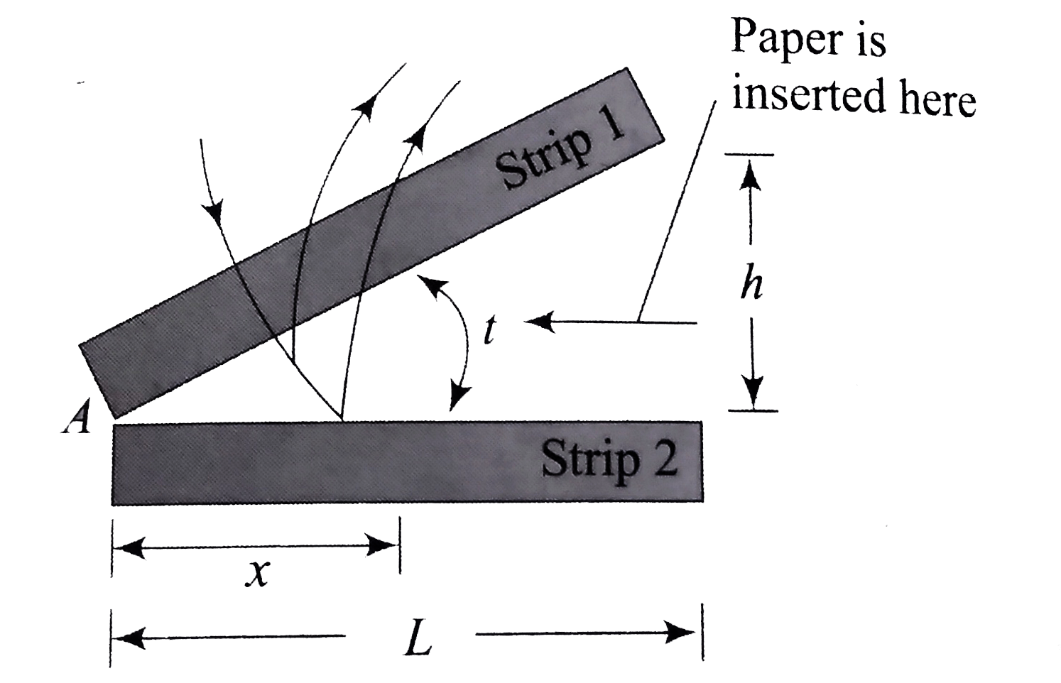
For data in question53 determine the distance of point B from the 20th dark band. Counting of dark point has to start from the contact point.
View SolutionA block o plastic having a thin air cavity (whose thickenss is comparable to wavelength of light waves) is shown in fig. The thickness of air cavity (which can be considered as air wedge for interference pattern) is varying linearly from one end to other as shown.
A broad beam of monochromatic light is incident normally from the top of the plastic box. Some ligth lis reflected back above and below the cavity .The plastic layers than wavelength of incident light . An observer when looking down from top sees an interference pattern consisting of eight dark fringes and seven bright fringe along the wedge. Take wavelength of incident light in air as `lambda_(0)` and refractive index of plastic as `mu`
Assume that the thickness of the ends of air cavity are such that formation of fringe takes place there.
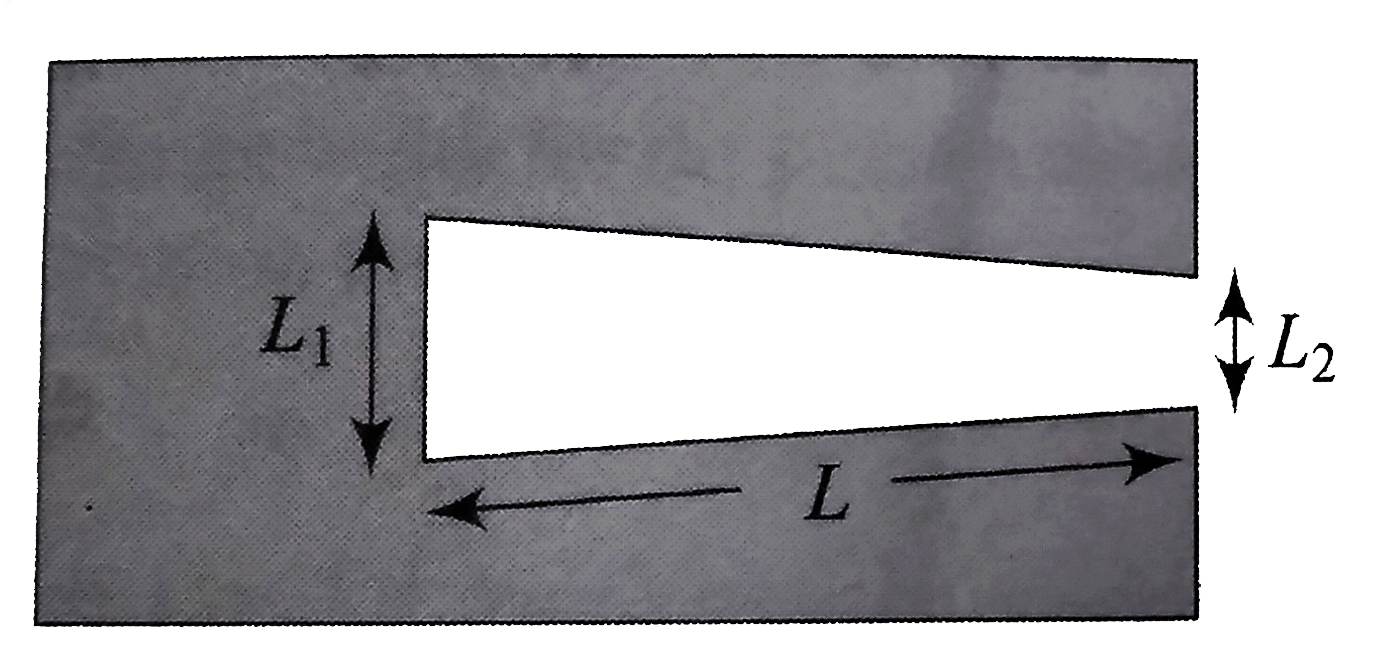
Determine of difference `L_(1) - L_(2) = Delta L)` in terms of `lambda_(0)`.
View SolutionA block o plastic having a thin air cavity (whose thickenss is comparable to wavelength of light waves) is shown in fig. The thickness of air cavity (which can be considered as air wedge for interference pattern) is varying linearly from one end to other as shown.
A broad beam of monochromatic light is incident normally from the top of the plastic box. Some ligth lis reflected back above and below the cavity .The plastic layers than wavelength of incident light . An observer when looking down from top sees an interference pattern consisting of eight dark fringes and seven bright fringe along the wedge. Take wavelength of incident light in air as `lambda_(0)` and refractive index of plastic as `mu`
Assume that the thickness of the ends of air cavity are such that formation of fringe takes place there.
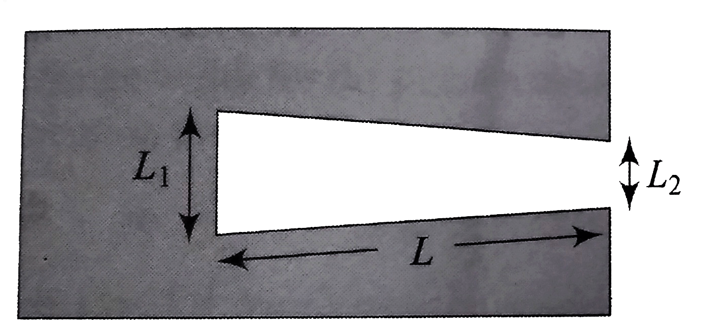
Determine the distance of 4th dark fringe from the left end of air cavity.
View SolutionA block o plastic having a thin air cavity (whose thickenss is comparable to wavelength of light waves) is shown in fig. The thickness of air cavity (which can be considered as air wedge for interference pattern) is varying linearly from one end to other as shown.
A broad beam of monochromatic light is incident normally from the top of the plastic box. Some ligth lis reflected back above and below the cavity .The plastic layers than wavelength of incident light . An observer when looking down from top sees an interference pattern consisting of eight dark fringes and seven bright fringe along the wedge. Take wavelength of incident light in air as `lambda_(0)` and refractive index of plastic as `mu`
Assume that the thickness of the ends of air cavity are such that formation of fringe takes place there.
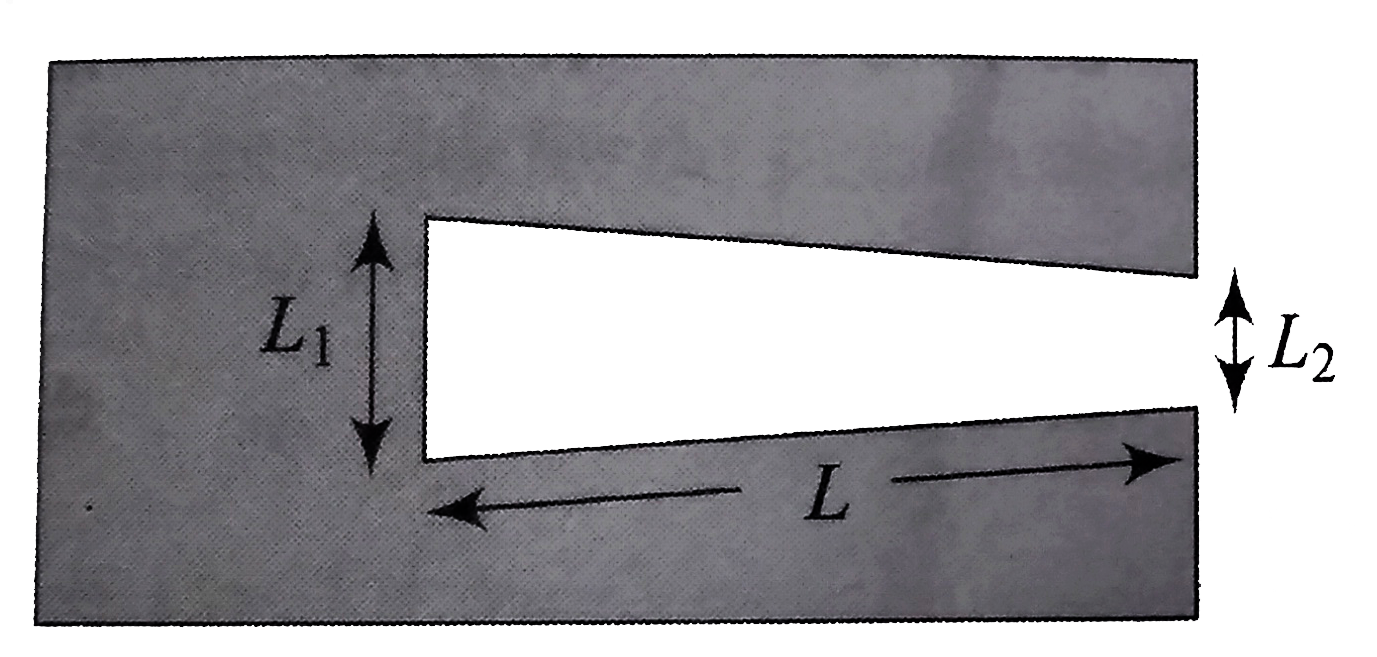
Determine the separation between 1st and 2nd dark fringes form the left end of air cavity
View SolutionIn fig., light of wavelength `lambda = 5000 Å` is incident on the slits (in a horizontally fixed place).
Here, `d = 1 mm` and `D = 1 m`
Take origin at O and XY plane as shown in the figure. The screen is released from rest from the initial position as shown
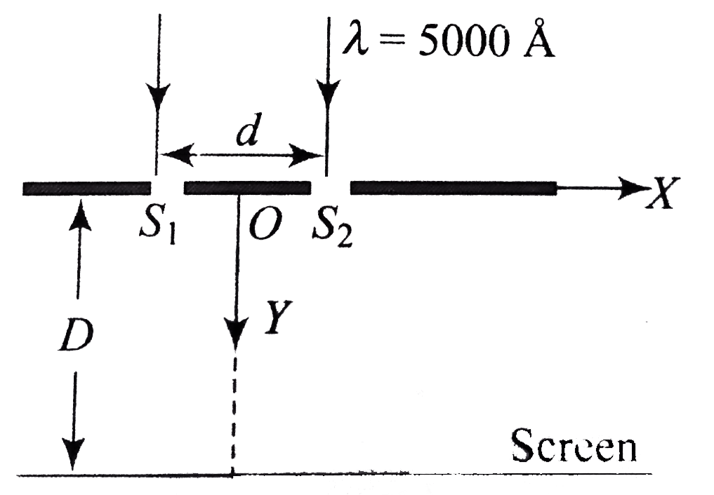
The velocity of central maxima at `t = 5 `s is
View SolutionIn fig., light of wavelength `lambda = 5000 Å` is incident on the slits (in a horizontally fixed place).
Here, `d = 1 mm` and `D = 1 m`
Take origin at O and XY plane as shown in the figure. The screen is released from rest from the initial position as shown
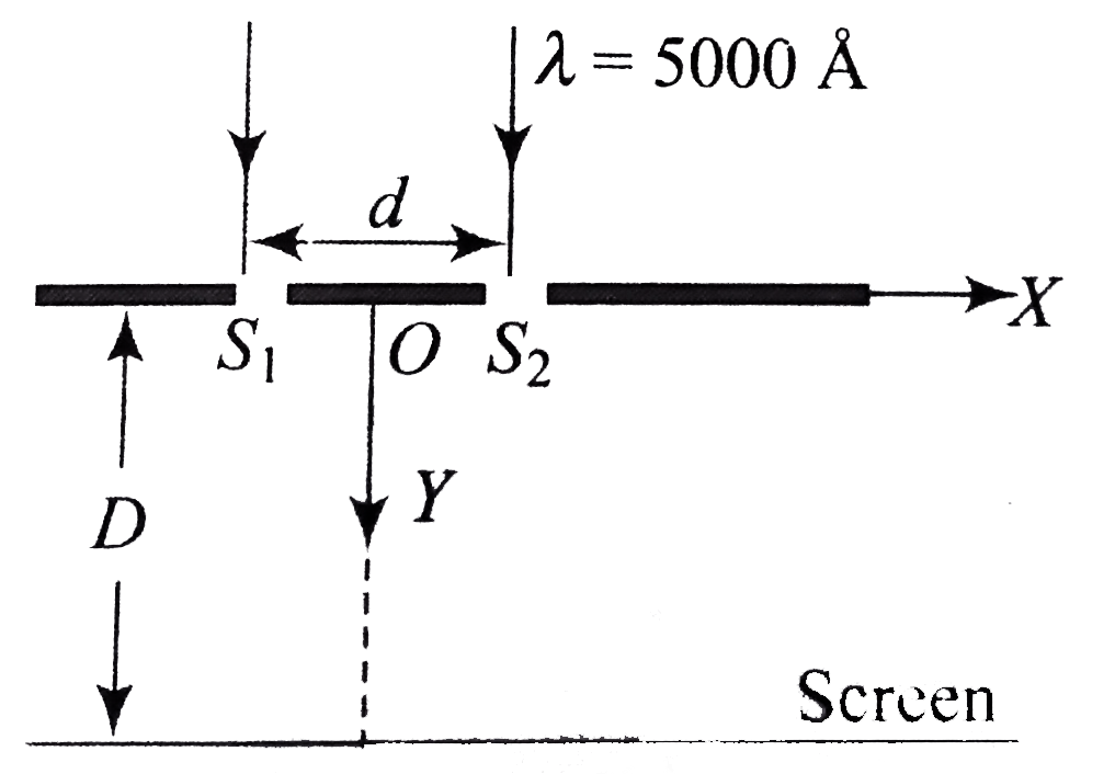
Velocity of 2nd maixma w.r.t central maxima at `t = 2`s is
View SolutionIn fig., light of wavelength `lambda = 5000 Å` is incident on the slits (in a horizontally fixed place).
Here, `d = 1 mm` and `D = 1 m`
Take origin at O and XY plane as shown in the figure. The screen is released from rest from the initial position as shown
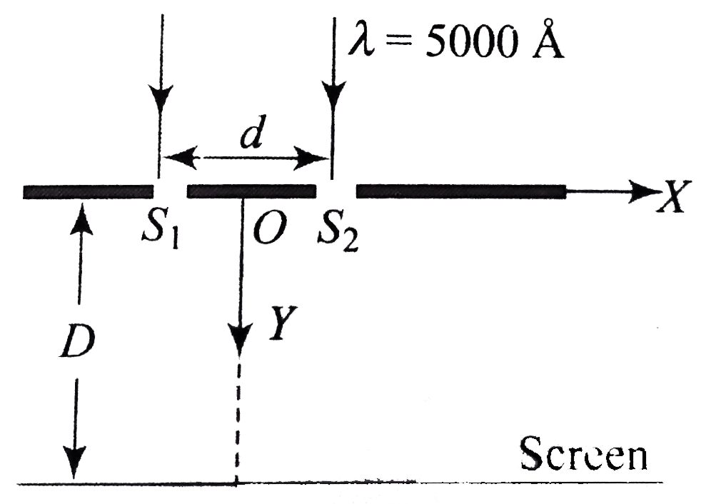
Acceleration of 3rd maxima w.r.t. 3rd maxiam on other side of central maxima at `t = 3` s is
View SolutionWhen two coherent sources interact with each other, there will be production of alternate bright and dark fringes on the screen . Young's double-slit experiment domonstrates the idea of making two coherent sources. For better visibility, one has to choose proper amplitude for the sources. The phenomena is good enough to satisfy the conservation of energy principle. The pattern formed in YDSE is of uniform thickness and is nicely placed on a long distance screen.
Law of convervation of energy is satisfied because
View SolutionWhen two coherent sources interact with each other, there will be production of alternate bright and dark fringes on the screen . Young's double-slit experiment domonstrates the idea of making two coherent sources. For better visibility, one has to choose proper amplitude for the sources. The phenomena is good enough to satisfy the conservation of energy principle. The pattern formed in YDSE is of uniform thickness and is nicely placed on a long distance screen.
For better visibility of fringe pattern
View SolutionWhen two coherent sources interact with each other, there will be production of alternate bright and dark fringes on the screen . Young's double-slit experiment domonstrates the idea of making two coherent sources. For better visibility, one has to choose proper amplitude for the sources. The phenomena is good enough to satisfy the conservation of energy principle. The pattern formed in YDSE is of uniform thickness and is nicely placed on a long distance screen.
The best combination of independent sources to produce sustained pattern among the following is
`Y_(1) = a sin omega t` `Y_(2) = a cos omega t`
`Y_(3) = a sin (omega t + (pi)/(4))` `Y_(4) = 2a sin (omega t + pi)`
View SolutionWhen a light wave passes from a rarer medium to a denser medium, there will be a phase change of `pi` radians. This difference brings change in the conditions for constructive and destructive interference. This phenomena also reasons the fromation of interference pattern in thin films like, oily layer, soap film, etc., but has no reason on the shifting of fringes from the central portion outward. The shift is dependent on the refractive index of the material as per the relation, `Delta y = (mu - 1) t`
Thin film interference happens with
View SolutionWhen a light wave passes from a rarer medium to a denser medium, there will be a phase change of `pi` radians. This difference brings change in the conditions for constructive and destructive interference. This phenomena also reasons the fromation of interference pattern in thin films like, oily layer, soap film, etc., but has no reason on the shifting of fringes from the central portion outward. The shift is dependent on the refractive index of the material as per the relation, `Delta y = (mu - 1) t`
On introducing a transparent slab `(mu)` the central fringe shifts to the point originally occupied by the fifth bright fringe. The thickness of the slab is
View SolutionWhen a light wave passes from a rarer medium to a denser medium, there will be a phase change of `pi` radians. This difference brings change in the conditions for constructive and destructive interference. This phenomena also reasons the fromation of interference pattern in thin films like, oily layer, soap film, etc., but has no reason on the shifting of fringes from the central portion outward. The shift is dependent on the refractive index of the material as per the relation, `Delta y = (mu - 1) t`
The condition for constructive interference in Lloyd's single mirror experiment is the path difference which is equal to
View SolutionWhen light from two sources (say slits `S_(1)` and `S_(2)`) interfere, they form alternate dark and bright fringes. Bright fringe is formed at all point where the path difference is an odd multiple of half wavelength. At the condition of equal amplitudes, `A_(1) = A_(2) = a`, the maximum intensity will be `4 a^(2)` and the visibility improves, The resultant intensity can also be indicated with phase factor as `I = 2 a^(2) cos^(2) (phi // 2)`.Using this passage, answer the following questions.
If the path difference between the slits `S_(1)` and `S_(2)` is `(lambda)/(2)` the central fringe will have an intensity of
View SolutionWhen light from two sources (say slits `S_(1)` and `S_(2)`) interfere, they form alternate dark and bright fringes. Bright fringe is formed at all point where the path difference is an odd multiple of half wavelength. At the condition of equal amplitudes, `A_(1) = A_(2) = a`, the maximum intensity will be `4 a^(2)` and the visibility improves, The resultant intensity can also be indicated with phase factor as `I = 2 a^(2) cos^(2) (phi // 2)`.Using this passage, answer the following questions.
At point having a path difference of `(lambda)/(4)`, the intensity
View SolutionWhen light from two sources (say slits `S_(1)` and `S_(2)`) interfere, they form alternate dark and bright fringes. Bright fringe is formed at all point where the path difference is an odd multiple of half wavelength. At the condition of equal amplitudes, `A_(1) = A_(2) = a`, the maximum intensity will be `4 a^(2)` and the visibility improves, The resultant intensity can also be indicated with phase factor as `I = 2 a^(2) cos^(2) (phi // 2)`.Using this passage, answer the following questions.
If the slits `S_(1)` and `S_(2)` are arranged as shown in Fig. the ratio of internsity of fringe at P and R is

View SolutionThin films, including soap bubbles and oil show patterns of alternative dark and bright regions resulting from interference among the reflected ligth waves. If two waves are in phase, their crests and troughs will coincide. The interference will be cosntructive and the amlitude of resultant wave will be greater then either of constituent waves. If the two wave are not of phase by half a wavelength `(180^(@))`, the crests of one wave will coincide width the troughs of the other wave. The interference will be destructive and the ampliutde of the resultant wave will be less than that of either consituent wave.
1. When incident light I, reaches the surface at point a, some of the ligth is reflected as ray `R_(a)` and some is refracted following the path ab to the back of the film.
2. At point b, some of the light is refracted out of the film and part is reflected back through the film along path bc. At point c, some of the light is reflected back into the film and part is reflected out of the film as ray `R_(c)`.
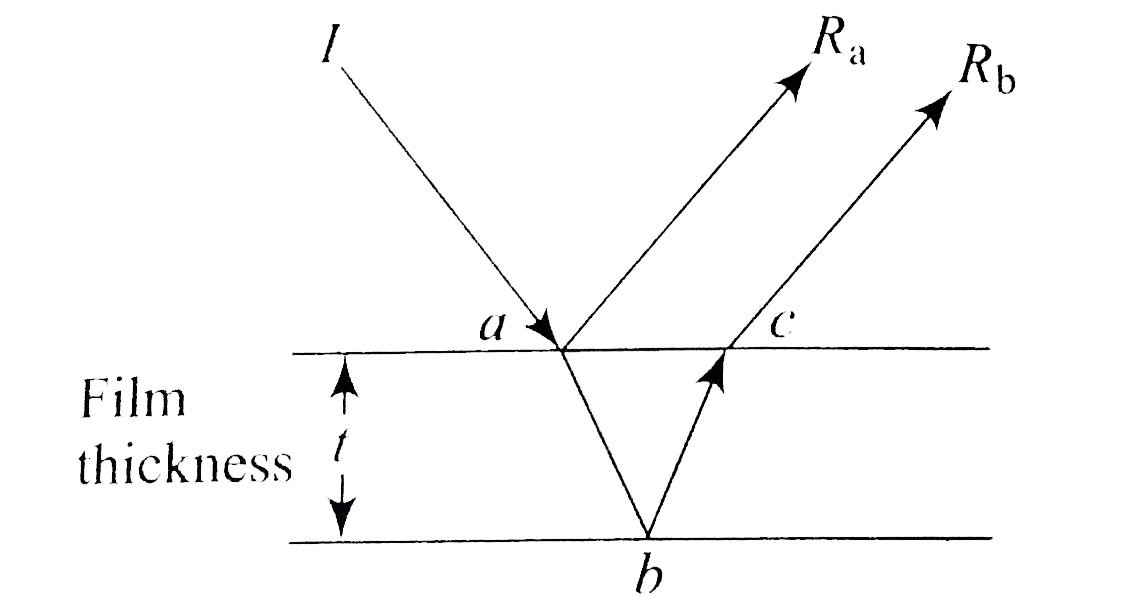
`R_(a)` and `R_(c)` are parallel. However, `R_(c)` has travelled the extra distance within the film fo abc. If the angle of incidence is small, then abc is approxmately twice the film's thickness .
If `R_(a)` and `R_(c)` are in phase, they will undergo constructive interference and the region ac will be bright. If `R_(a)` and `R_(c)` are out of phase, they will undergo destructive interference and the region ac will be dark.
I. Refraction at an interface never changes the phase of the wave.
II. For reflection at the interfere between two media 1 and 2, if `n_(1) gt n_(2)`, the reflected wave will change phase. If `n_(1) lt n_(2)`, the reflected wave will not undergo a phase change.
For reference, `n_(air) = 1.00`.
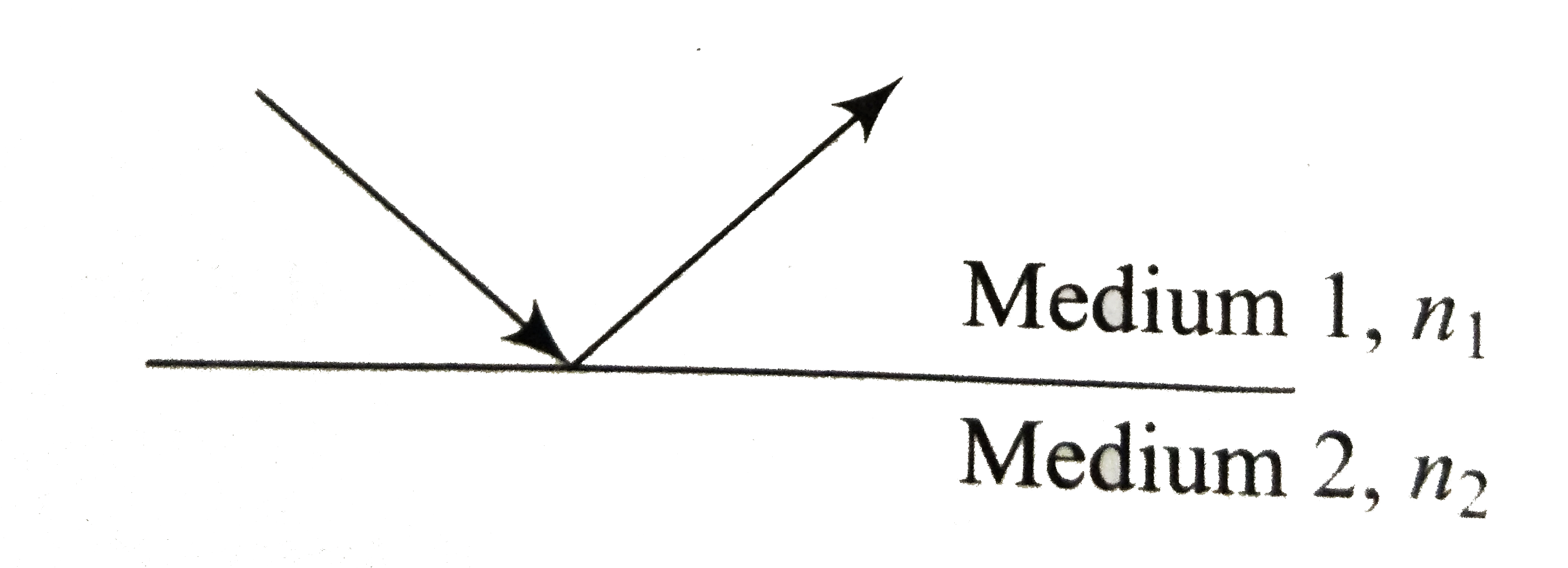
III. If the waves are in phase after reflection at all intensities, then the effects of path length in the film are:
Constrictive interference occurs when `2 t = m lambda // n, m = 0, 1,2,3`,...
Destrcutive interference occurs when `2 t = (m + (1)/(2)) (lambda)/(n)`,
`m = 0, 1, 2, 3`,...
If the waves are `180^(@)` out of the phase after reflection at all interference, then the effects of path length in the film ara:
Constructive interference occurs when
`2 t = (m + (1)/(2)) (lambda)/(n), m = 0, 1, 2, 3`,...
Destructive interference occurs when
`2 t = (m lambda)/(n) , m = 0, 1, 2, 3`,...
72. A film with index of refraction 1.50 coats a glass lens with index of refraction 1.80. What is the minimum thickness of the thin film that will strongly reflect light with wavelength 600 nm?
View SolutionThin films, including soap bubbles and oil show patterns of alternative dark and bright regions resulting from interference among the reflected ligth waves. If two waves are in phase, their crests and troughs will coincide. The interference will be cosntructive and the amlitude of resultant wave will be greater then either of constituent waves. If the two wave are not of phase by half a wavelength `(180^(@))`, the crests of one wave will coincide width the troughs of the other wave. The interference will be destructive and the ampliutde of the resultant wave will be less than that of either consituent wave.
1. When incident light I, reaches the surface at point a, some of the ligth is reflected as ray `R_(a)` and some is refracted following the path ab to the back of the film.
2. At point b, some of the light is refracted out of the film and part is reflected back through the film along path bc. At point c, some of the light is reflected back into the film and part is reflected out of the film as ray `R_(c)`.
`R_(a)` and `R_(c)` are parallel. However, `R_(c)` has travelled the extra distance within the film fo abc. If the angle of incidence is small, then abc is approxmately twice the film's thickness .
If `R_(a)` and `R_(c)` are in phase, they will undergo constructive interference and the region ac will be bright. If `R_(a)` and `R_(c)` are out of phase, they will undergo destructive interference and the region ac will be dark.
I. Refraction at an interface never changes the phase of the wave.
II. For reflection at the interfere between two media 1 and 2, if `n_(1) gt n_(2)`, the reflected wave will change phase. If `n_(1) lt n_(2)`, the reflected wave will not undergo a phase change.
For reference, `n_(air) = 1.00`.
III. If the waves are in phase after reflection at all intensities, then the effects of path length in the film are:
Constrictive interference occurs when `2 t = m lambda // n, m = 0, 1,2,3`,...
Destrcutive interference occurs when `2 t = (m + (1)/(2)) (lambda)/(n)`,
`m = 0, 1, 2, 3`,...
If the waves are `180^(@)` out of the phase after reflection at all interference, then the effects of path length in the film ara:
Constructive interference occurs when
`2 t = (m + (1)/(2)) (lambda)/(n), m = 0, 1, 2, 3`,...
Destructive interference occurs when
`2 t = (m lambda)/(n) , m = 0, 1, 2, 3`,...
A thin film with index of refraction 1.33 coats a glass lens with index of refraction 1.50. Which of the following choices is the smallest film thickness that will not reflect light with wavelength 640 nm?
View SolutionThin films, including soap bubbles and oil show patterns of alternative dark and bright regions resulting from interference among the reflected ligth waves. If two waves are in phase, their crests and troughs will coincide. The interference will be cosntructive and the amlitude of resultant wave will be greater then either of constituent waves. If the two wave are not of phase by half a wavelength `(180^(@))`, the crests of one wave will coincide width the troughs of the other wave. The interference will be destructive and the ampliutde of the resultant wave will be less than that of either consituent wave.
1. When incident light I, reaches the surface at point a, some of the ligth is reflected as ray `R_(a)` and some is refracted following the path ab to the back of the film.
2. At point b, some of the light is refracted out of the film and part is reflected back through the film along path bc. At point c, some of the light is reflected back into the film and part is reflected out of the film as ray `R_(c)`.
`R_(a)` and `R_(c)` are parallel. However, `R_(c)` has travelled the extra distance within the film fo abc. If the angle of incidence is small, then abc is approxmately twice the film's thickness .
If `R_(a)` and `R_(c)` are in phase, they will undergo constructive interference and the region ac will be bright. If `R_(a)` and `R_(c)` are out of phase, they will undergo destructive interference and the region ac will be dark.
I. Refraction at an interface never changes the phase of the wave.
II. For reflection at the interfere between two media 1 and 2, if `n_(1) gt n_(2)`, the reflected wave will change phase. If `n_(1) lt n_(2)`, the reflected wave will not undergo a phase change.
For reference, `n_(air) = 1.00`.
III. If the waves are in phase after reflection at all intensities, then the effects of path length in the film are:
Constrictive interference occurs when `2 t = m lambda // n, m = 0, 1,2,3`,...
Destrcutive interference occurs when `2 t = (m + (1)/(2)) (lambda)/(n)`,
`m = 0, 1, 2, 3`,...
If the waves are `180^(@)` out of the phase after reflection at all interference, then the effects of path length in the film ara:
Constructive interference occurs when
`2 t = (m + (1)/(2)) (lambda)/(n), m = 0, 1, 2, 3`,...
Destructive interference occurs when
`2 t = (m lambda)/(n) , m = 0, 1, 2, 3`,...
A soap film of thickness t is surrounded by air and is illuminated at near normal incidence by noonochromatic light wavelength `lambda` in the film. With respect to the wavelength of the monochromatic ligth in the film, what film thickness will produce maximum consturctive interference
View SolutionThin films, including soap bubbles and oil show patterns of alternative dark and bright regions resulting from interference among the reflected ligth waves. If two waves are in phase, their crests and troughs will coincide. The interference will be cosntructive and the amlitude of resultant wave will be greater then either of constituent waves. If the two wave are not of phase by half a wavelength `(180^(@))`, the crests of one wave will coincide width the troughs of the other wave. The interference will be destructive and the ampliutde of the resultant wave will be less than that of either consituent wave.
1. When incident light I, reaches the surface at point a, some of the ligth is reflected as ray `R_(a)` and some is refracted following the path ab to the back of the film.
2. At point b, some of the light is refracted out of the film and part is reflected back through the film along path bc. At point c, some of the light is reflected back into the film and part is reflected out of the film as ray `R_(c)`.
`R_(a)` and `R_(c)` are parallel. However, `R_(c)` has travelled the extra distance within the film fo abc. If the angle of incidence is small, then abc is approxmately twice the film's thickness .
If `R_(a)` and `R_(c)` are in phase, they will undergo constructive interference and the region ac will be bright. If `R_(a)` and `R_(c)` are out of phase, they will undergo destructive interference and the region ac will be dark.
I. Refraction at an interface never changes the phase of the wave.
II. For reflection at the interfere between two media 1 and 2, if `n_(1) gt n_(2)`, the reflected wave will change phase. If `n_(1) lt n_(2)`, the reflected wave will not undergo a phase change.
For reference, `n_(air) = 1.00`.
III. If the waves are in phase after reflection at all intensities, then the effects of path length in the film are:
Constrictive interference occurs when `2 t = m lambda // n, m = 0, 1,2,3`,...
Destrcutive interference occurs when `2 t = (m + (1)/(2)) (lambda)/(n)`,
`m = 0, 1, 2, 3`,...
If the waves are `180^(@)` out of the phase after reflection at all interference, then the effects of path length in the film ara:
Constructive interference occurs when
`2 t = (m + (1)/(2)) (lambda)/(n), m = 0, 1, 2, 3`,...
Destructive interference occurs when
`2 t = (m lambda)/(n) , m = 0, 1, 2, 3`,...
The average human eye sees colors with wavelength between 430 nm to 680 nm. For what visible wavelength (s) will a 350 nm thick `(n = 1.35)` soap film produce maximum destructive interference?
View SolutionThin films, including soap bubbles and oil show patterns of alternative dark and bright regions resulting from interference among the reflected ligth waves. If two waves are in phase, their crests and troughs will coincide. The interference will be cosntructive and the amlitude of resultant wave will be greater then either of constituent waves. If the two wave are not of phase by half a wavelength `(180^(@))`, the crests of one wave will coincide width the troughs of the other wave. The interference will be destructive and the ampliutde of the resultant wave will be less than that of either consituent wave.
1. When incident light I, reaches the surface at point a, some of the ligth is reflected as ray `R_(a)` and some is refracted following the path ab to the back of the film.
2. At point b, some of the light is refracted out of the film and part is reflected back through the film along path bc. At point c, some of the light is reflected back into the film and part is reflected out of the film as ray `R_(c)`.
`R_(a)` and `R_(c)` are parallel. However, `R_(c)` has travelled the extra distance within the film fo abc. If the angle of incidence is small, then abc is approxmately twice the film's thickness .
If `R_(a)` and `R_(c)` are in phase, they will undergo constructive interference and the region ac will be bright. If `R_(a)` and `R_(c)` are out of phase, they will undergo destructive interference and the region ac will be dark.
I. Refraction at an interface never changes the phase of the wave.
II. For reflection at the interfere between two media 1 and 2, if `n_(1) gt n_(2)`, the reflected wave will change phase. If `n_(1) lt n_(2)`, the reflected wave will not undergo a phase change.
For reference, `n_(air) = 1.00`.
III. If the waves are in phase after reflection at all intensities, then the effects of path length in the film are:
Constrictive interference occurs when `2 t = m lambda // n, m = 0, 1,2,3`,...
Destrcutive interference occurs when `2 t = (m + (1)/(2)) (lambda)/(n)`,
`m = 0, 1, 2, 3`,...
If the waves are `180^(@)` out of the phase after reflection at all interference, then the effects of path length in the film ara:
Constructive interference occurs when
`2 t = (m + (1)/(2)) (lambda)/(n), m = 0, 1, 2, 3`,...
Destructive interference occurs when
`2 t = (m lambda)/(n) , m = 0, 1, 2, 3`,...
A 600 nm light is perpendicularly incident on a soap film suspended air. The film is 1.00 `mu m` thick with `n = `.37`. Which statement most accurately describes the interference of ligth reflected by the two surfaces of the film?
View SolutionThin films, including soap bubbles and oil show patterns of alternative dark and bright regions resulting from interference among the reflected ligth waves. If two waves are in phase, their crests and troughs will coincide. The interference will be cosntructive and the amlitude of resultant wave will be greater then either of constituent waves. If the two wave are not of phase by half a wavelength `(180^(@))`, the crests of one wave will coincide width the troughs of the other wave. The interference will be destructive and the ampliutde of the resultant wave will be less than that of either consituent wave.
1. When incident light I, reaches the surface at point a, some of the ligth is reflected as ray `R_(a)` and some is refracted following the path ab to the back of the film.
2. At point b, some of the light is refracted out of the film and part is reflected back through the film along path bc. At point c, some of the light is reflected back into the film and part is reflected out of the film as ray `R_(c)`.
`R_(a)` and `R_(c)` are parallel. However, `R_(c)` has travelled the extra distance within the film fo abc. If the angle of incidence is small, then abc is approxmately twice the film's thickness .
If `R_(a)` and `R_(c)` are in phase, they will undergo constructive interference and the region ac will be bright. If `R_(a)` and `R_(c)` are out of phase, they will undergo destructive interference and the region ac will be dark.
I. Refraction at an interface never changes the phase of the wave.
II. For reflection at the interfere between two media 1 and 2, if `n_(1) gt n_(2)`, the reflected wave will change phase. If `n_(1) lt n_(2)`, the reflected wave will not undergo a phase change.
For reference, `n_(air) = 1.00`.
III. If the waves are in phase after reflection at all intensities, then the effects of path length in the film are:
Constrictive interference occurs when `2 t = m lambda // n, m = 0, 1,2,3`,...
Destrcutive interference occurs when `2 t = (m + (1)/(2)) (lambda)/(n)`,
`m = 0, 1, 2, 3`,...
If the waves are `180^(@)` out of the phase after reflection at all interference, then the effects of path length in the film ara:
Constructive interference occurs when
`2 t = (m + (1)/(2)) (lambda)/(n), m = 0, 1, 2, 3`,...
Destructive interference occurs when
`2 t = (m lambda)/(n) , m = 0, 1, 2, 3`,...
A thin of liquid polymer, `n = 1.25`, coats a slab of pyrex, `n = 1.50`. White light is incident perpendicularly on the film. In the reflection, full destructive interference occurs for `lambda = 600 nm` and full constructive interference occurs for `lambda = 700 nm` What is the thickness of the polymer film?
View SolutionIn YDSE set up (see fig.), the light sources executes SHM between P and Q according to the equation `x = A sin omega t`, S being the mean position. Assume `d rarr 0` and `A lt lt L`. `omega` is small enough to neglect Doppler effect. If the sources were stationary at S, intenstiy at O would be `I_(0)`
Read the paragraph carefully and answer the following questions.
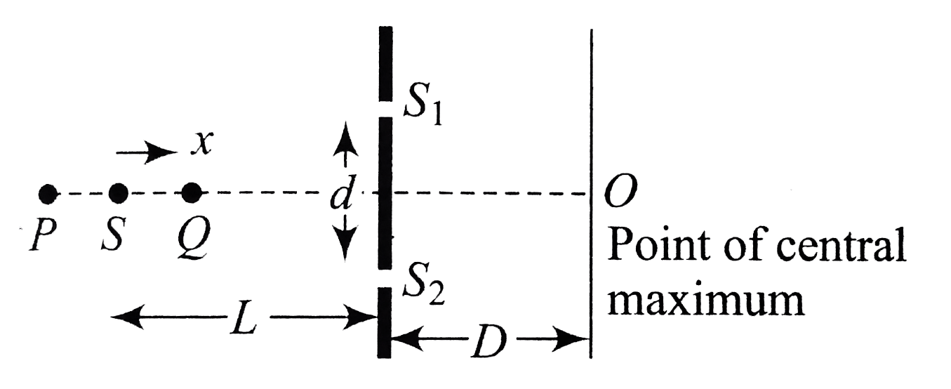
The fractional change in intensity of the central maximum as function of time is
View SolutionIn YDSE set up (see fig.), the light sources executes SHM between P and Q according to the equation `x = A sin omega t`, S being the mean position. Assume `d rarr 0` and `A lt lt L`. `omega` is small enough to neglect Doppler effect. If the sources were stationary at S, intenstiy at O would be `I_(0)`
Read the paragraph carefully and answer the following questions.
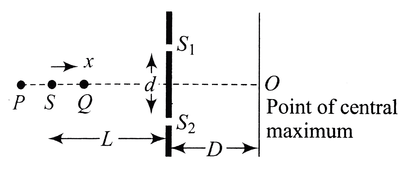
When the source comes toward the point Q,
View SolutionIn YDSE set up (see fig.), the light sources executes SHM between P and Q according to the equation `x = A sin omega t`, S being the mean position. Assume `d rarr 0` and `A lt lt L`. `omega` is small enough to neglect Doppler effect. If the sources were stationary at S, intenstiy at O would be `I_(0)`
Read the paragraph carefully and answer the following questions.
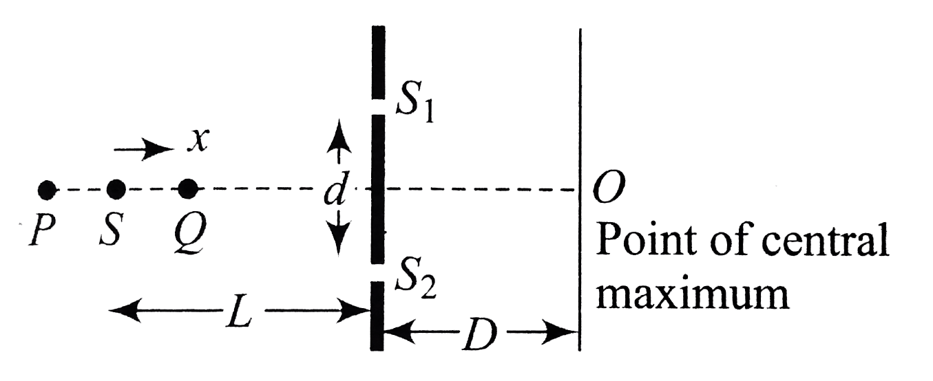
The fringe width `beta` can be expressed as
View SolutionIn the arrangement shown in Fig., slits `S_(1)` and `S_(4)`are having a variable separation Z. Point O on the screen is at the common perpendicular bisector of `S_(1) S_(2)` and `S_(3) S_(4)`.
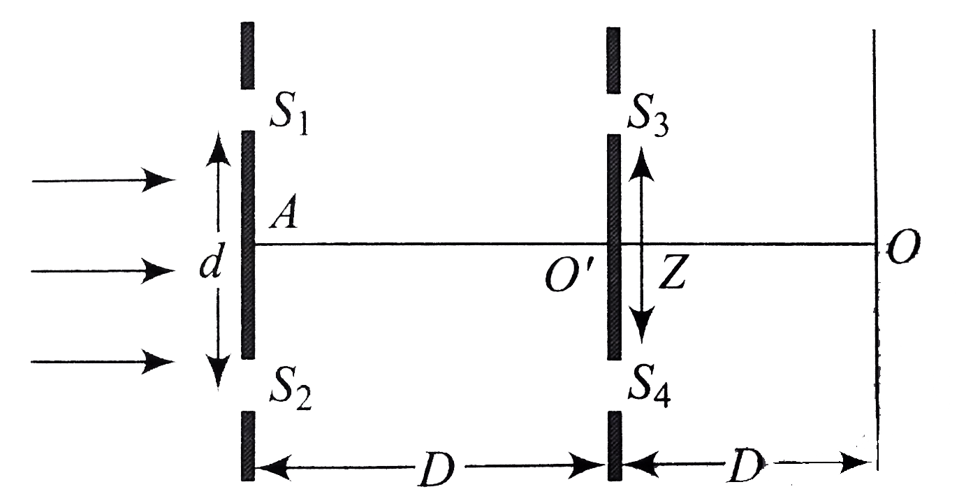
When `Z = (lambda D)/(2d)`, the intensity measured at O is `I_(0)`. The intensity at O When `Z = (2 lambda D)/(d)` is
View SolutionIn the arrangement shown in Fig., slits `S_(1)` and `S_(4)`are having a variable separation Z. Point O on the screen is at the common perpendicular bisector of `S_(1) S_(2)` and `S_(3) S_(4)`.
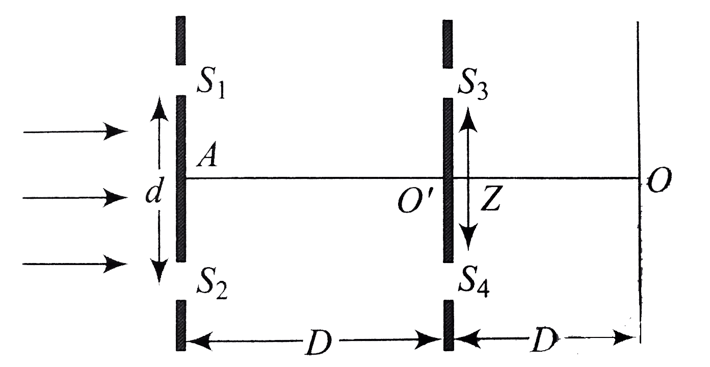
The minimum value of Z for which the intensity at O is zero is
View SolutionIn the arrangement shown in Fig., slits `S_(1)` and `S_(4)`are having a variable separation Z. Point O on the screen is at the common perpendicular bisector of `S_(1) S_(2)` and `S_(3) S_(4)`.
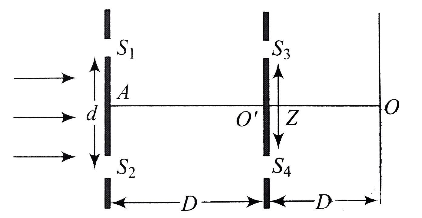
If a hole is made at O' on AO' O and the slit `S_(4)` is closed, then the ratio of the maximum to minimum observed on screen at O , if `O' S_(3)` is equal to `(lambda D)/(4d)`, is
View SolutionIn Young's double-slit experiment `lambda = 500 nm, d = 1 mm`, and `D = 4 m`. The minimum distance from the central maximum for which the intensity is half of the maximum intensity is `'**' xx 10^(-4) m`. What is the value of `'**'`?
View SolutionA monochromatic light of `lambda = 500 Å` is incident on two indentical slits separated by a distance of `5 xx 10^(-4)` m. The interference pattern is seen on a screen placed at a distance of 1 m from the plane of slits. A thin glass plate of thickness `1.5 xx 10^(-6)` m and refractive index `mu = 1.5` is placed between one of the slits and the screen . Find the intensity at the center of the screen.
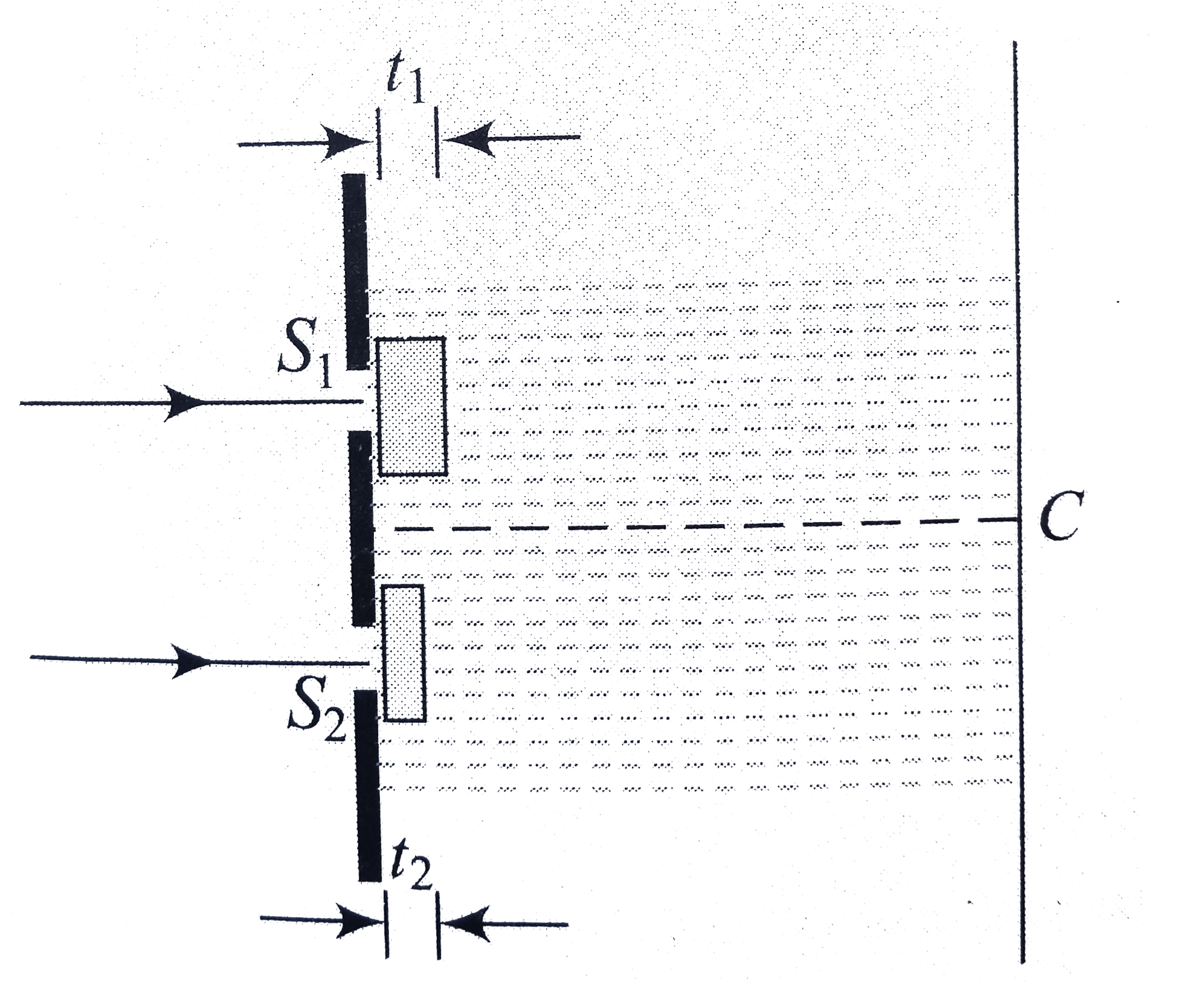
View SolutionA screen is at distance `D = 80` cm form a diaphragm having two narrow slits `S_(1)` and `S_(2)` which are `d = 2` mm apart.
Slit `S_(1)` is covered by a transparent sheet of thickness
`t_(1) = 2.5 mu m` slit `S_(2)` is covered by another sheet of thikness
`t_(2) = 1.25 mu m` as shown if Fig. 2.52.
Both sheets are made of same material having refractive index `mu = 1.40`
Water is filled in the space between diaphragm and screen. Amondichromatic light beam of wavelength `lambda = 5000 Å` is incident normally on the diaphragm.
Assuming intensity of beam to be uniform, calculate ratio of intensity of C to maximum intensity of interference pattern obtained on the screen `(mu_(w) = 4//3)`
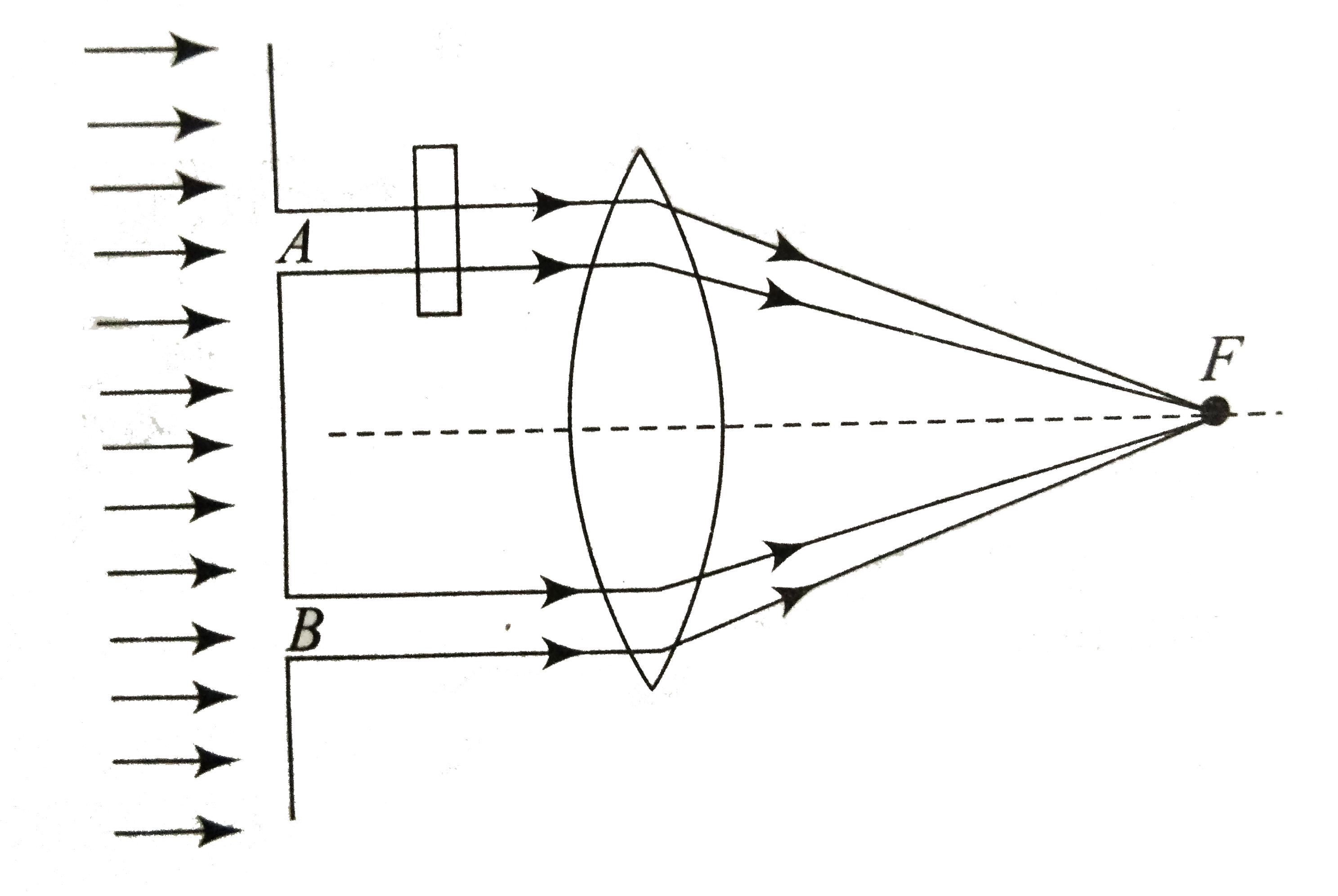
View SolutionIn a modified Young's double-slit experiment, a monochromatic uniform and parallel beam of light of wavelength `6000 Å` and intensity `(10//pi)` W `m^(-2)` is incident normally on two circular apertures A and B of radii 0.001 m and 0.002 m, respectively. A perfectly transparent film of thickness `2000 Å` and refractive index 1.5 for the wavelength of `6000 Å` is placed in front of aperture A (see the figure). Calculate the power (in mW) received at the focal spot F of the lens. Then lens is symmetrically placed with respect to the aperture. Assume that 10% of the power received by each aperture goes in the original direction and is brought to the focal spot.
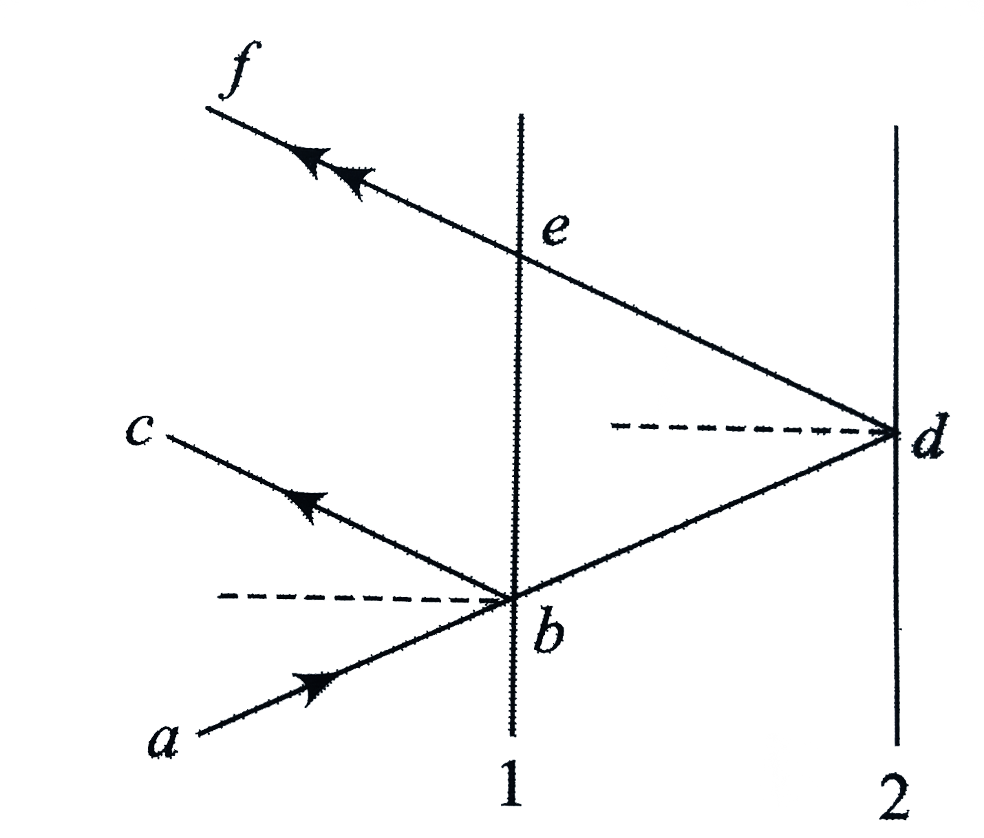
View SolutionA narrow monochromatic beam of light of intensity 1 is incident on a glass plate as shown in figure Another identical glass plate is kept close to the first one and parallel to it. Each glass plate reflects `25%` of the light incident on it and transmits intensities in the interference pattern formed by two beams obtained after one reflection at each plate.
View Solution
Linked Comprehension questions and complete solutions for chapter WAVE OPTICS of CENGAGE PHYSICS (HINGLISH) of Class 12


