In a series L-R growth circuit, if maximum current and maximum voltage across inductor of inductane 3mH are 2A and 6V respectively, the the time constant of the circuit is
1ms
2ms
0.5ms
0.6ms
The correct Answer is:A
To solve the problem, we need to find the time constant of the series LR circuit given the inductance and the maximum current and voltage across the inductor. Here’s a step-by-step solution:
Step 1: Identify the given values
- Inductance (L) = 3 mH = 3 × 10^(-3) H
- Maximum Current (I_max) = 2 A
- Maximum Voltage (V_max) = 6 V
Step 2: Use Ohm's Law to find the resistance (R)
We know that the voltage across the inductor in a series LR circuit can be expressed using Ohm's Law:
V=I×R
Rearranging this gives us:
R=VI
Substituting the given values:
R=6V2A=3Ω
Step 3: Calculate the time constant (τ)
The time constant (τ) for an LR circuit is given by the formula:
τ=LR
Substituting the values we have:
τ=3×10⁻³H3Ω=1×10⁻³s=1ms
Conclusion
The time constant of the circuit is:
τ=1ms
Final Answer
The time constant of the circuit is 1 ms.
---
- Inductance (L) = 3 mH = 3 × 10^(-3) H
- Maximum Current (I_max) = 2 A
- Maximum Voltage (V_max) = 6 V
We know that the voltage across the inductor in a series LR circuit can be expressed using Ohm's Law:
V=I×R
R=VI
R=6V2A=3Ω
The time constant (τ) for an LR circuit is given by the formula:
τ=LR
τ=3×10⁻³H3Ω=1×10⁻³s=1ms
The time constant of the circuit is:
τ=1ms
The time constant of the circuit is 1 ms.
Topper's Solved these Questions
Similar Questions
In a series resonant circuit, the ac, voltage across resistance R, inductance L and capacitance are 5V, 10V and 10V, respectively. The ac. voltage applied to the circuit will be
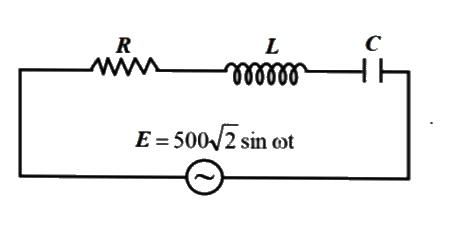
View SolutionIn the series L−C−R circuit shown in the figure, the rms voltage across the resistor and inductor are 400 V and 700 V respectively. If the applied voltage is E=500√2sin(ωt), then the peak voltage across the capacitor is

View Solution
Knowledge Check
In a series LCR circuit the voltage across an inductor, capacitor and resistor are 20 V, 20 V and 40 V respectively. The phase difference between the applied voltage and the current in the circuit is
A30∘B45∘C60∘D0∘
In a series LCR circuit R=200(Ω) and the voltage and the frequency of the main supply is 220V and 50 Hz respectively. On taking out the capacitance from the circuit the current lags behind the voltage by 30(∘). On taking out the inductor from the circuit the current leads the voltage by 30(∘). The power dissipated in the LCR circuit is
View SolutionIn an LCR series ac circuit the voltage across L,C and R are V1,V2 and V3 respectively The voltage of the source is .
View SolutionIn series LCR circuit, the phase difference between voltage across L and voltage across C is
View SolutionIn a series LCR circuit the rms voltage across the inductance , capacitance and resistance are respectively 4 V, 8 V and 5 V . The RMS voltage of the AC source in the circuit is
View SolutionIn a series LCR circuit, the voltages across an inductor, a capacitor and a resistor are 30 V, 30 V, 60 V respectively. What is the phase difference between the applied voltage and the current in the circuit ?
View SolutionIn a series LCR circuit, the voltages across an inductor, a capacitor and a resistor are 30 V, 30 V, 60 V respectively. What is the phase difference between the applied voltage and the current in the circuit ?
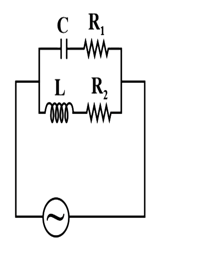
View SolutionIn the given circuit the R.M.S values of voltages across the capacitor C, inductor L and resistor R1 are 12V, 10V and 5 V respectively. Then the peak voltage across R2 is

View Solution
