Exercise 3.1 from CENGAGE PHYSICS (HINGLISH) ELECTROMAGNETIC INDUCTION for Class 12
| Class 12 | PHYSICS |
| Chapter | ELECTROMAGNETIC INDUCTION |
| CENGAGE PHYSICS (HINGLISH) | Exercise 3.1 |
| Medium | English |
| Academic Year | 2023-2024 |
Question 3
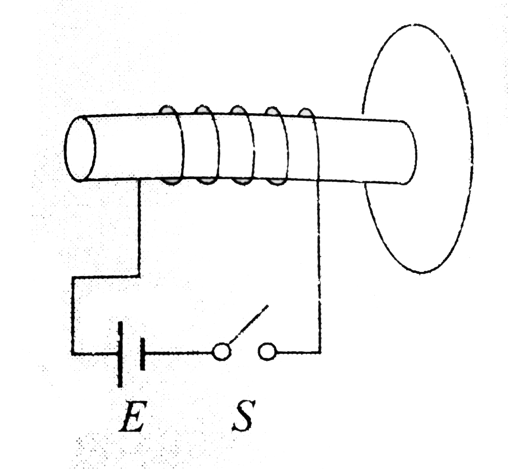
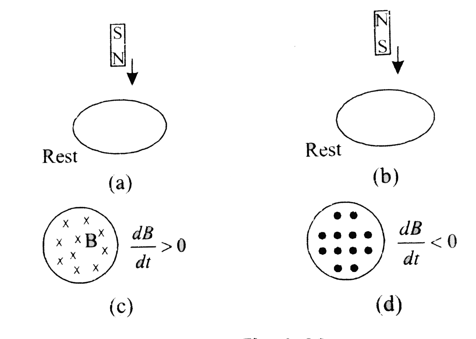
A conducting ring is placed near a solenoid as shown in Fig.3.21. Find the direction of the induced current in the ring.
(a) At the instant the switch in the circuit containing the solenoid is closed.
(b) After the switch has been closed for a long time.
(c) At the instant the switch is opened.
 View Solution
Question 5
Using Lenz's law, determine the direction of the current in resistor ab in Fig. 3.23 when
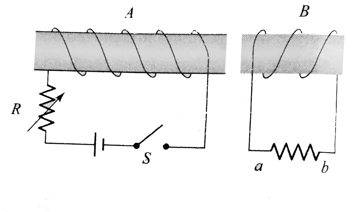
(a) switch S is opended after having been closed for several minutes.
(b) coil B is brought closer to coil A with the swich closed. ltbr> ( c) the resistance of R is decreased while the switch remains closed. View SolutionQuestion 6
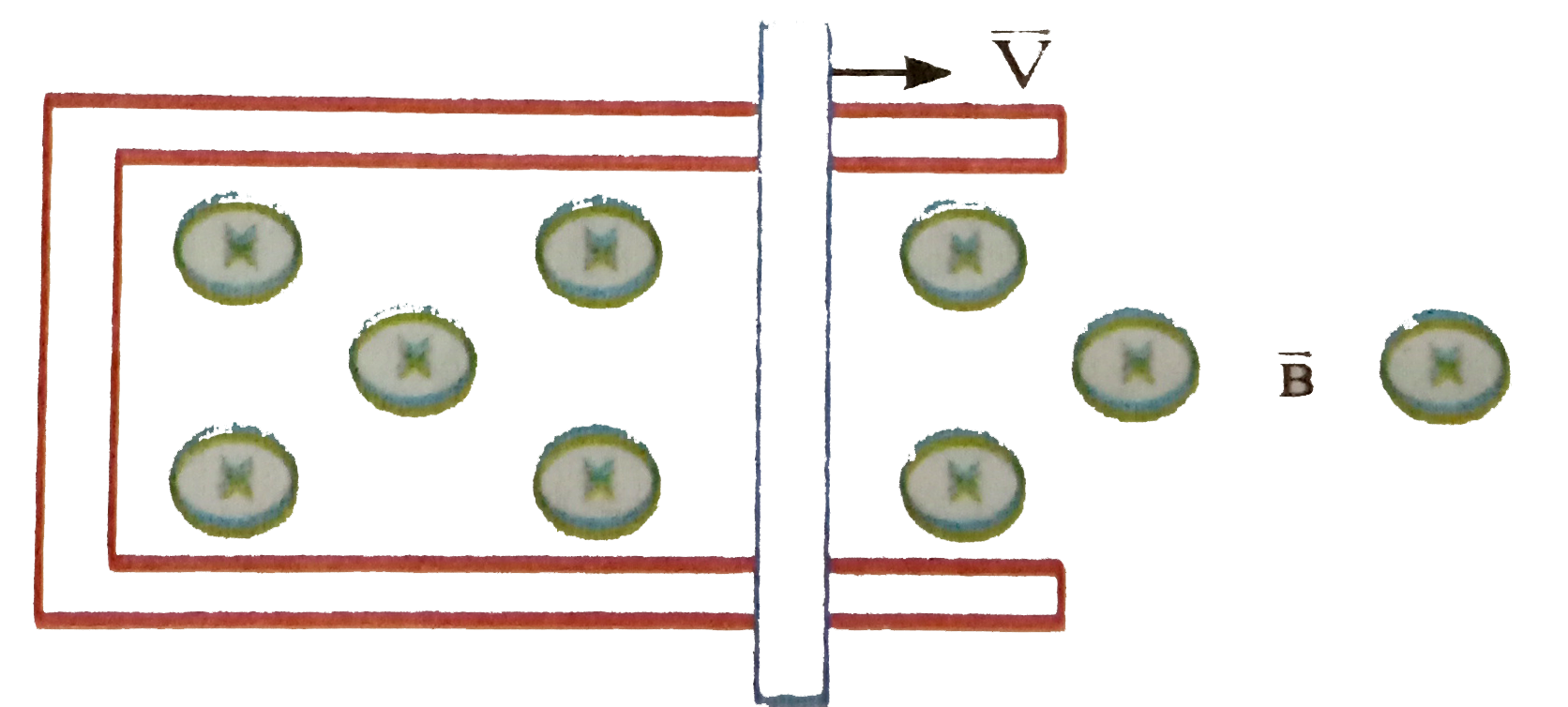
A carboard tube is wrapped with two winding of insulated wire wound in opposite directions as shown in Fig. 3.24. Terminal aandb of winding A may be connected to a battery through a reversing switch. State whether the induced current in the resistor R from left to right or from right to left in the following cicumstances.
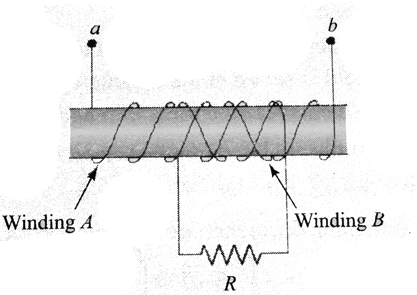
(a) The current in winding A is from a→b and is increasing.
(b) The current in winding A is from b→a and is decreasing.
( c) The current in winding A is from b→a and is increasing.View SolutionQuestion 7
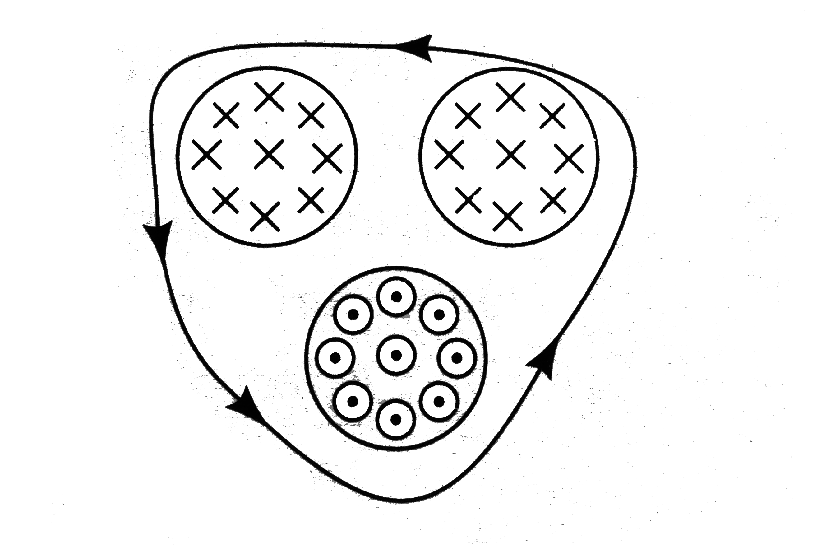
A small, circular ring is inside a larger loop that is connected to a battery and a switch as shown in Fig. 3.25. Use Lenz's law to find the direction of the current induced in the small ring
(a) just after switch S is closed,
(b) after Shas been closed for a long time,
( c) just after S has been reopened after being closed for a long time. ltbr>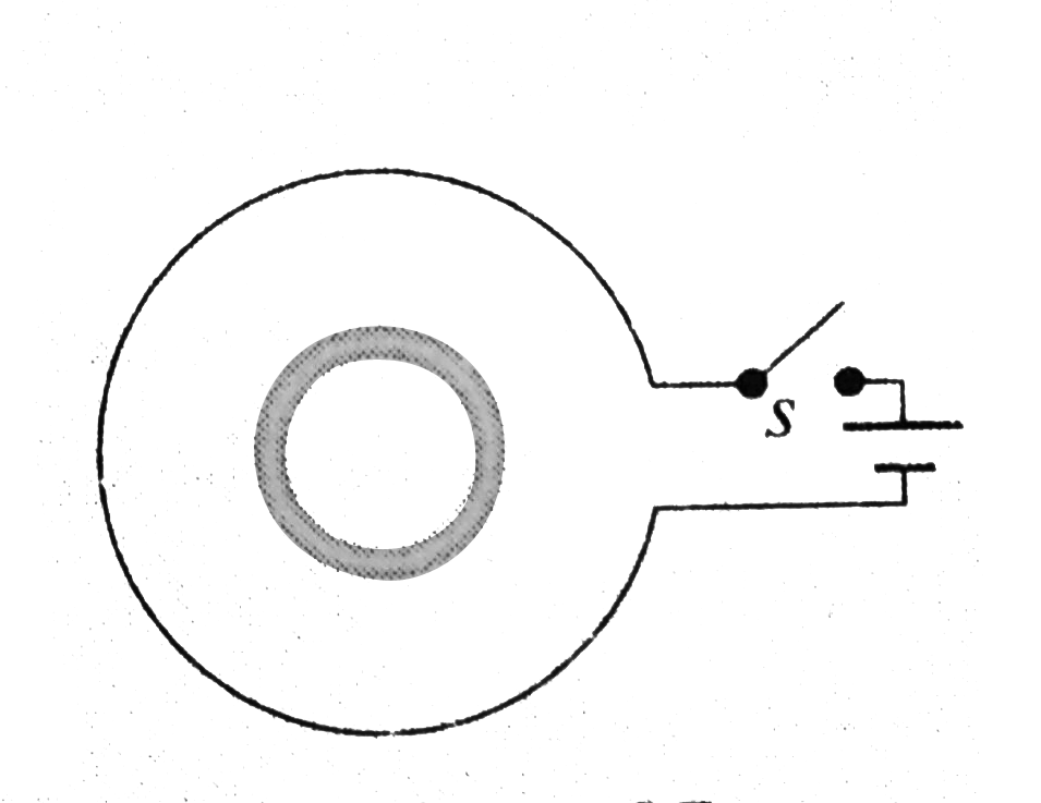 View Solution
Question 8
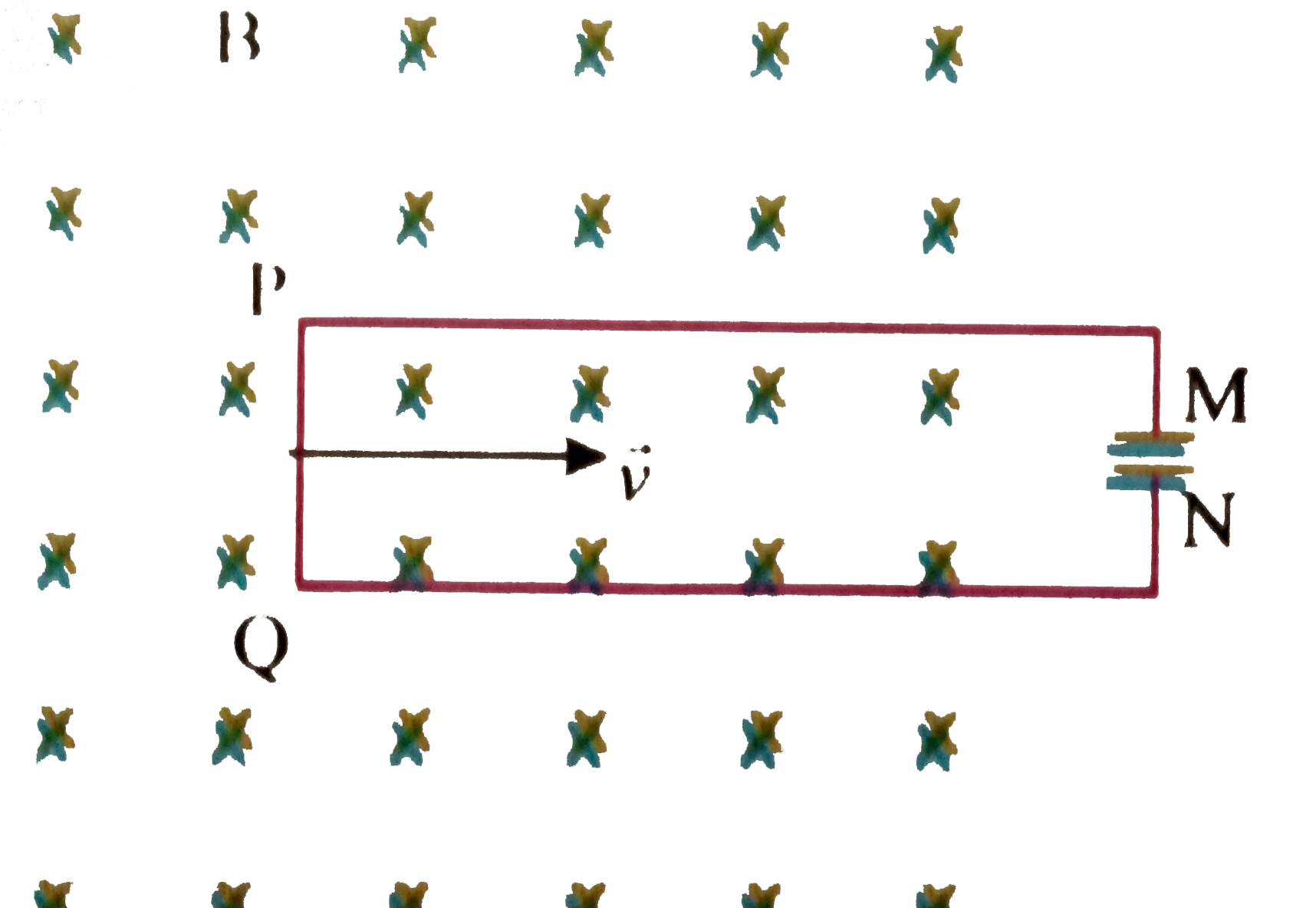
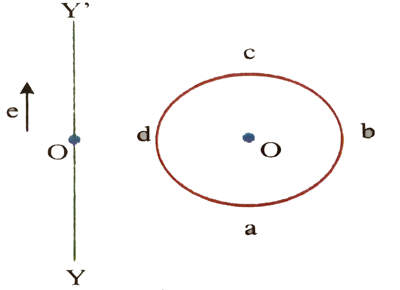
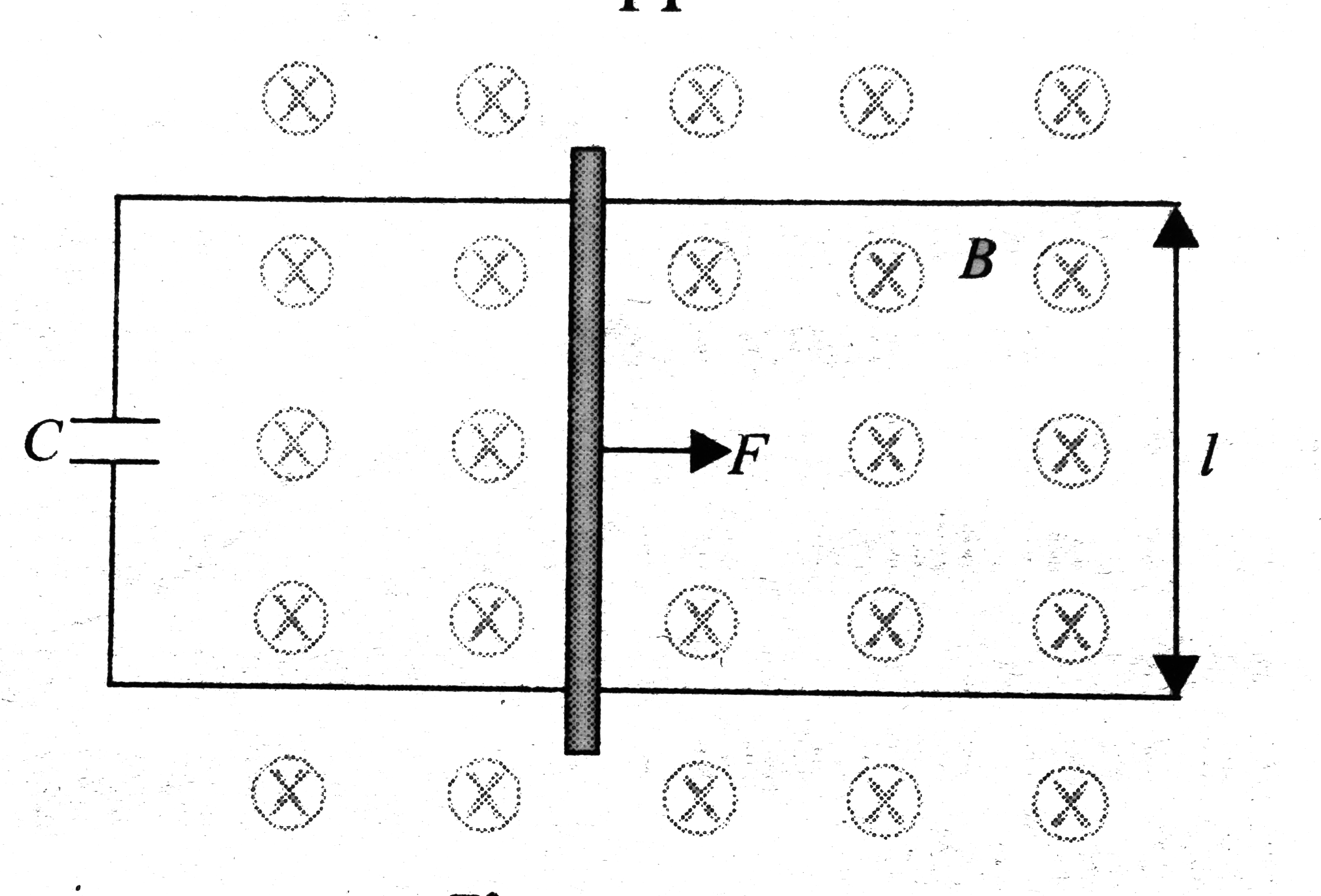
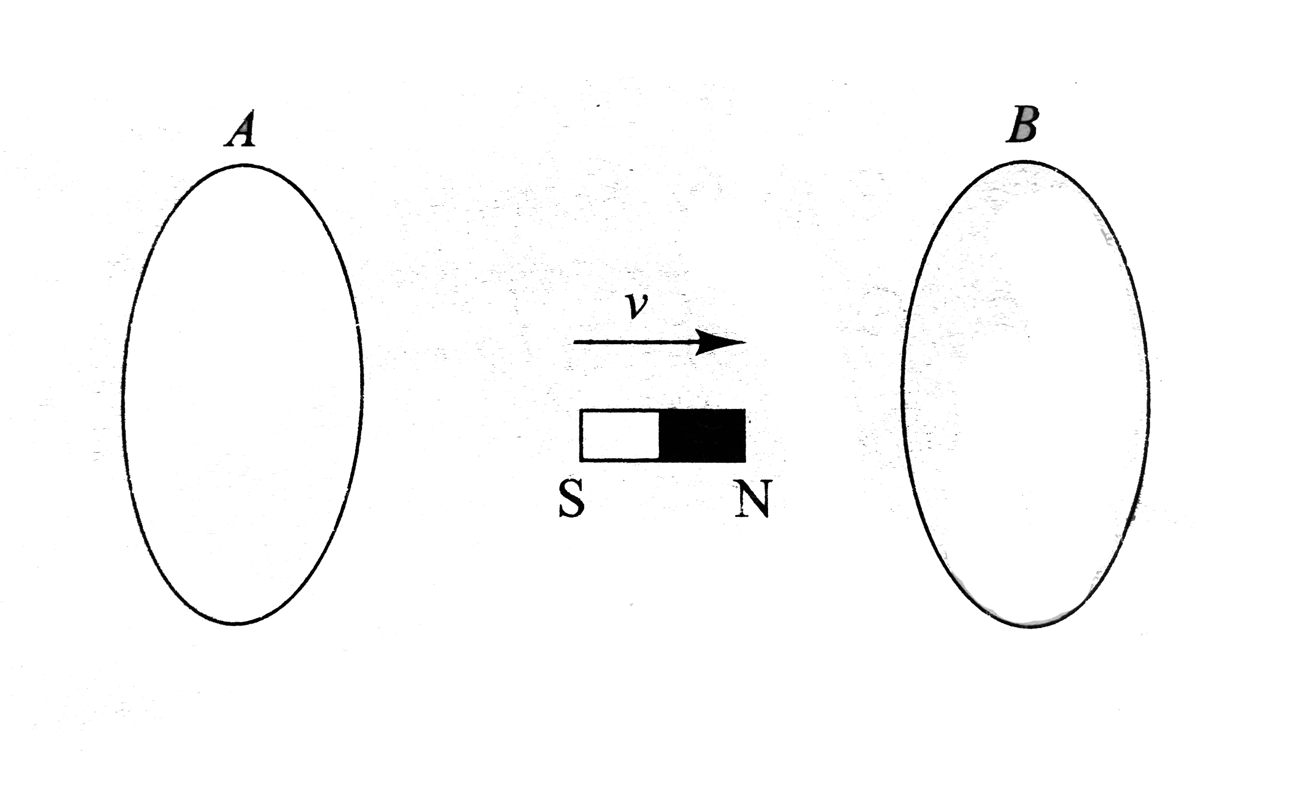
(a). Predict the polarity of capacitor C as shown in Fig. 3.26 when poles S and N of two identical magnets approach the coil from opposote sides with equal velocity. The plane of the loop containing the capacitor is perpendicualr to the plane of the paper.

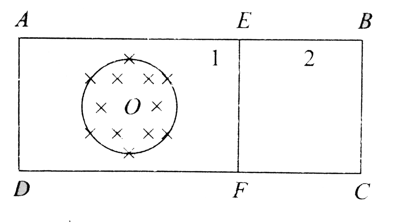
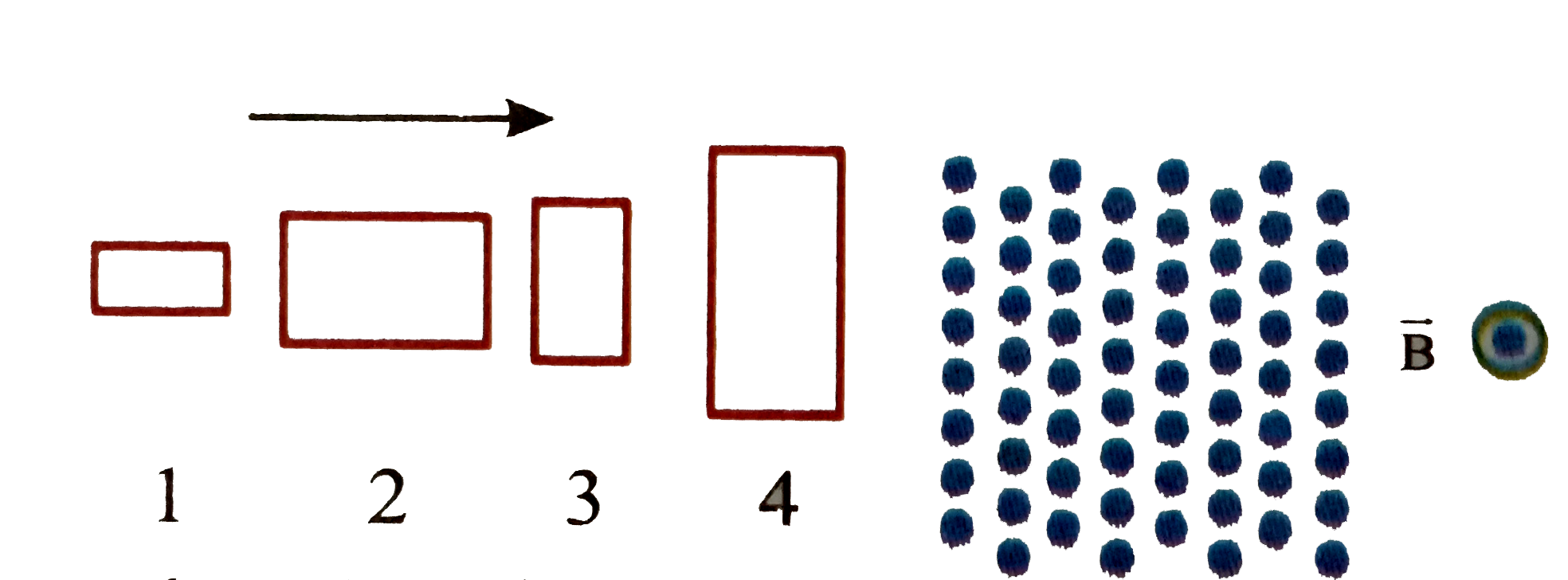
(b). A magnetic field perpendicular to the plane of a rectangular frame of wire is concentrated about O. If the field decreases, will there be any emf induced in loop 1? What about loop 2? Explain why.
 View Solution
Question 12
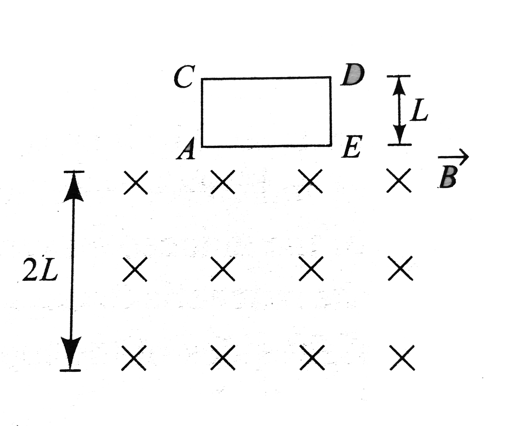
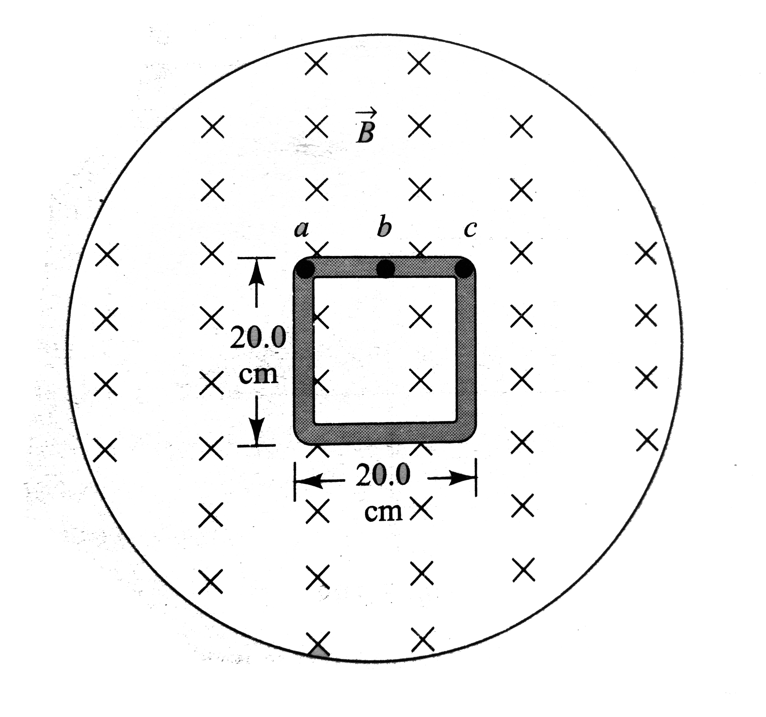
A square loop of wire with resistance R is moved at constant speed v across a uniform magnet field confined to a square region whose sides are twice the lengths of those of the square loop
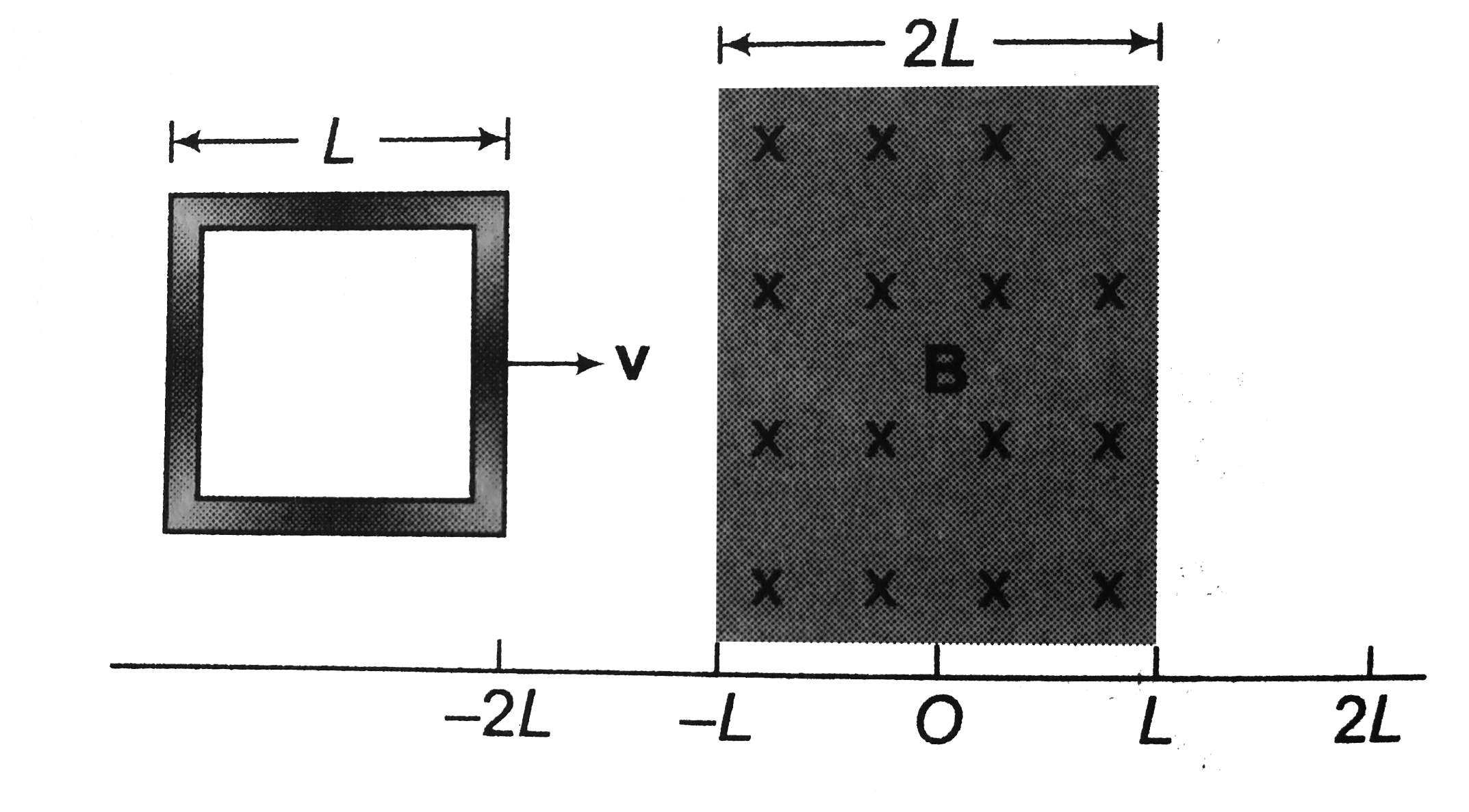
(a) Sketch a graph of the external forces F needed to move the loop at constant speed, as a function of to sketch a graph of the external force F need tho coordinate x, fromx=−2L to x=+2L. (The coordinate x is measured from the centre of the oignetic field region to the centre of the loop. It is negative when the centre of the loop is to the left, of the centre of the magnetic field region. Take positive force to be to the right). (b) Sketch a graph of the induced current in the loop as a function of x. Take counterclockwise currents to be positive. View SolutionQuestion 14
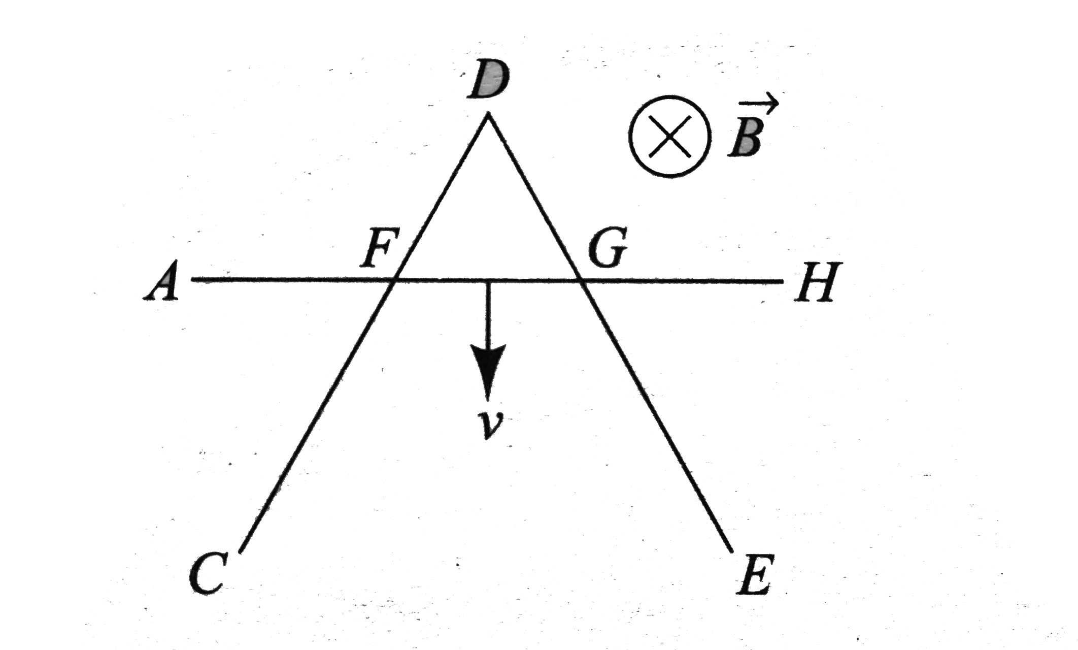
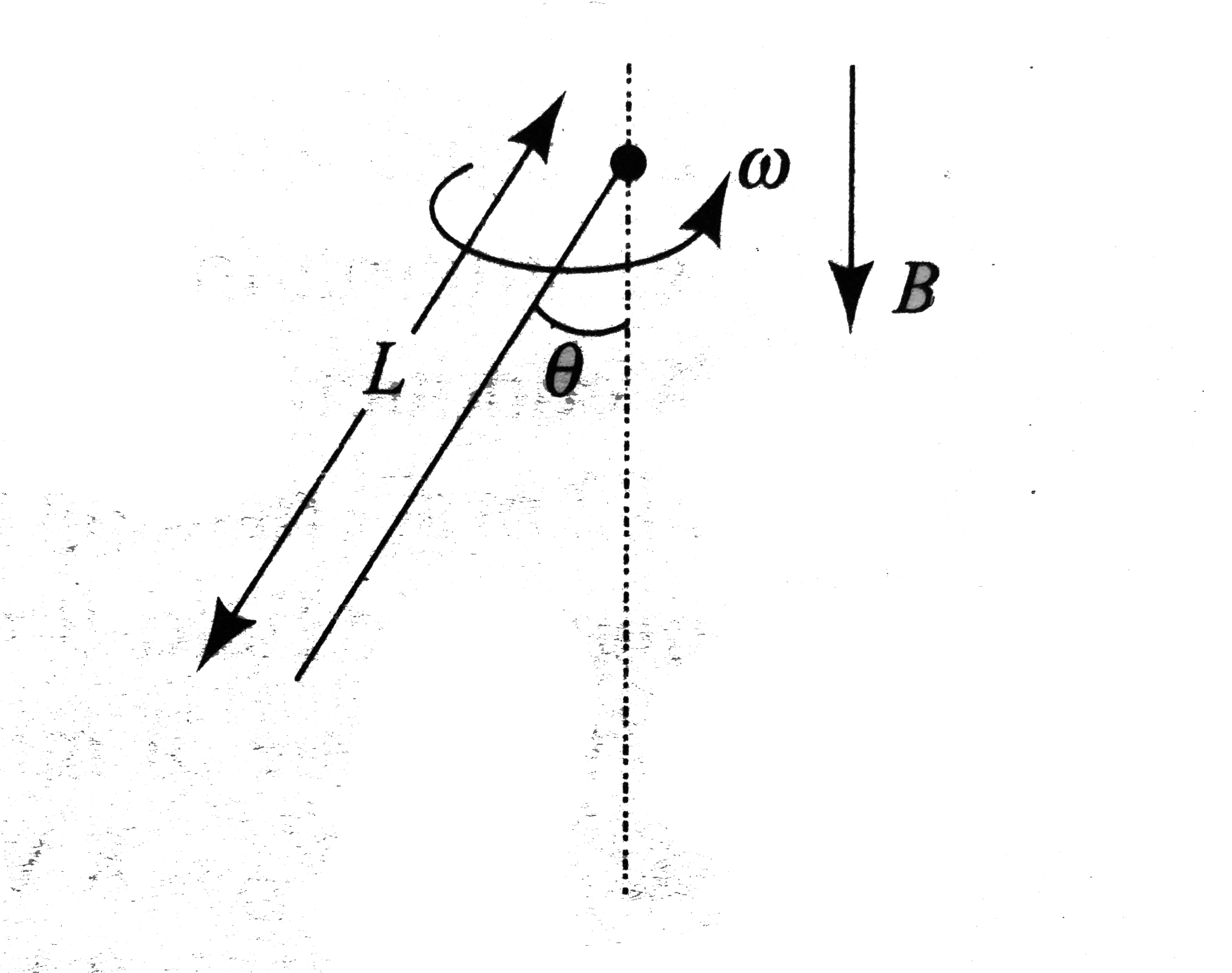
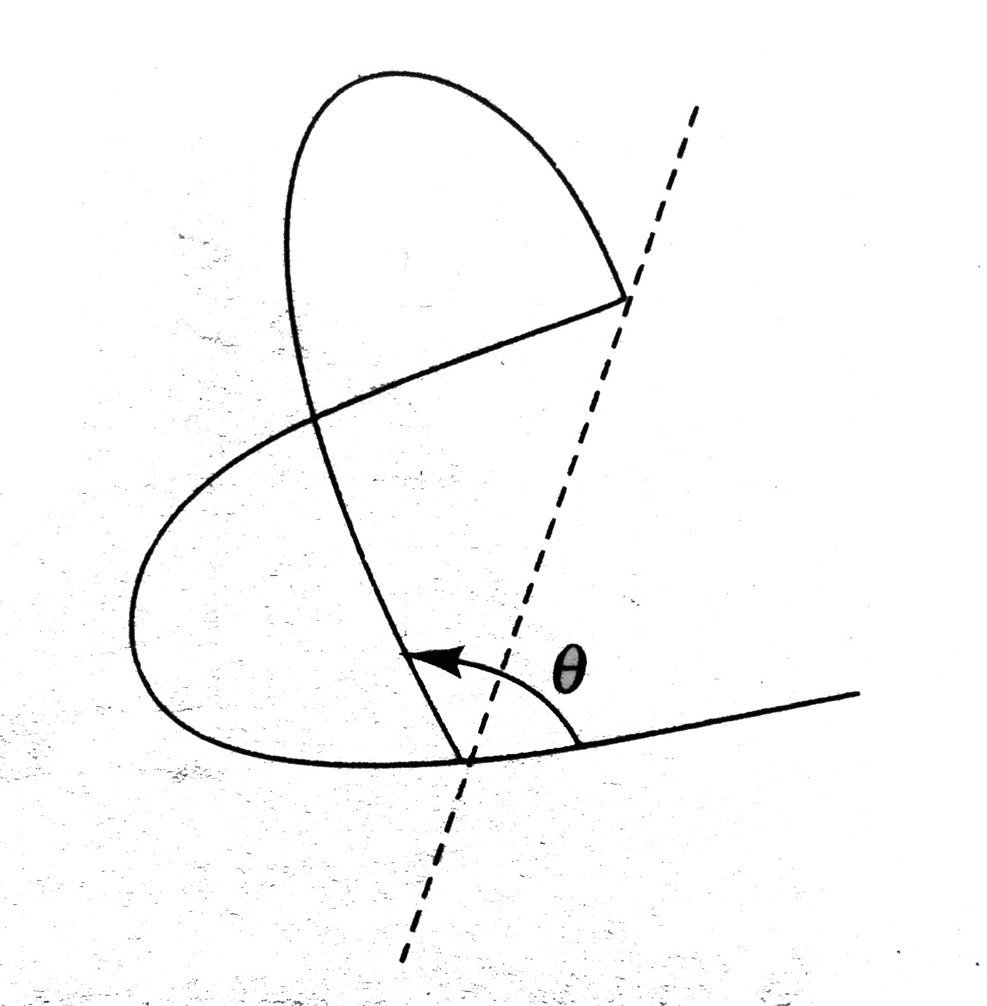
The wire shown in is bent in the shape of a tent, with θ=60.0∘ and L=1.50m, and placed in a uniform magnetic field of magnitude 0.300T perpendicular to the tabletop. The wire is rigid but hinged at points aandb. If the tent is flattened out on the table in 0.100s, what is the average induced emf in the wire during this time?
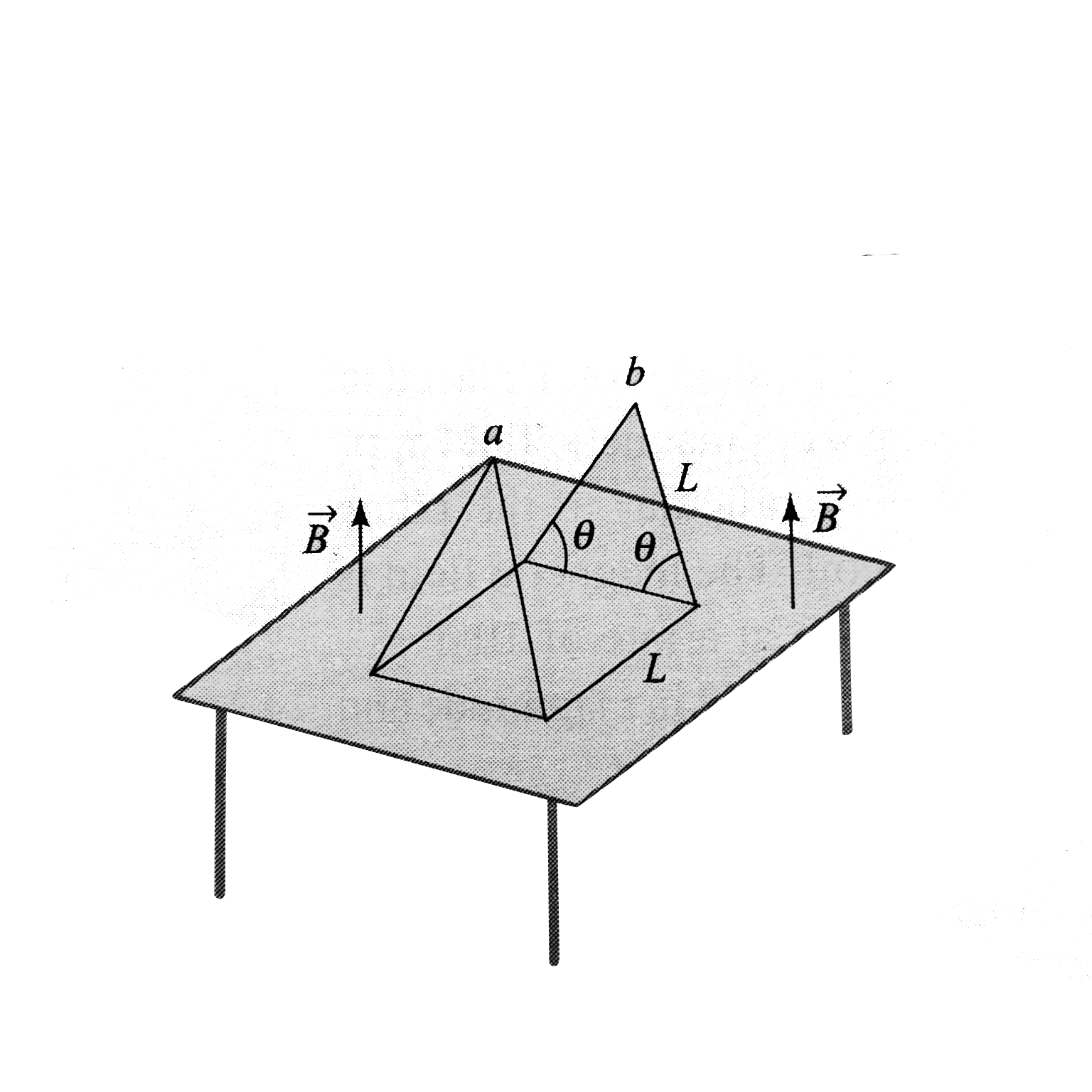 View Solution
Question 15
The plane of a square loop of wire edge length a=0.200m is perpendicualr to the Earth's magnetic field at a point where B=15.0μT, as shown in . The total resistance of the loop and the wires connecting it to a sensitive ammeter is 0.50Ω. If the loop is suddenly collapsed by horizontal forces as shown, what is the total charge passing through the ammeter?
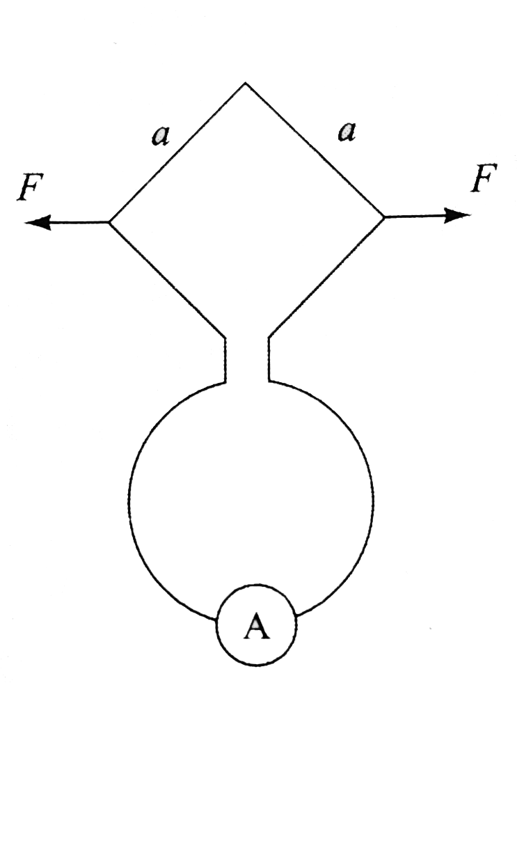 View Solution
Question 30
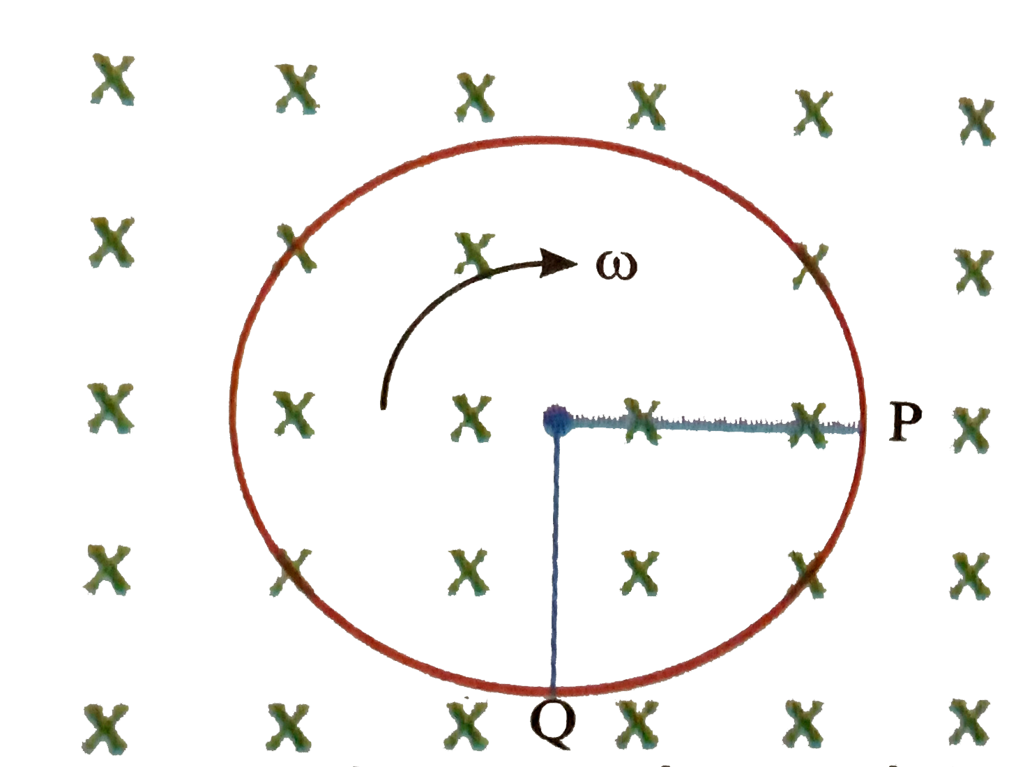
A rod of length L and resistance r rotates about one end as shown in . Its other end touches a conducting ring of negligible resistence. A resistence R is connected between the center and periphery. Draw the electrical equivalence and find the current in resistance R. There is a uniform magnetic field B directed as shown in .
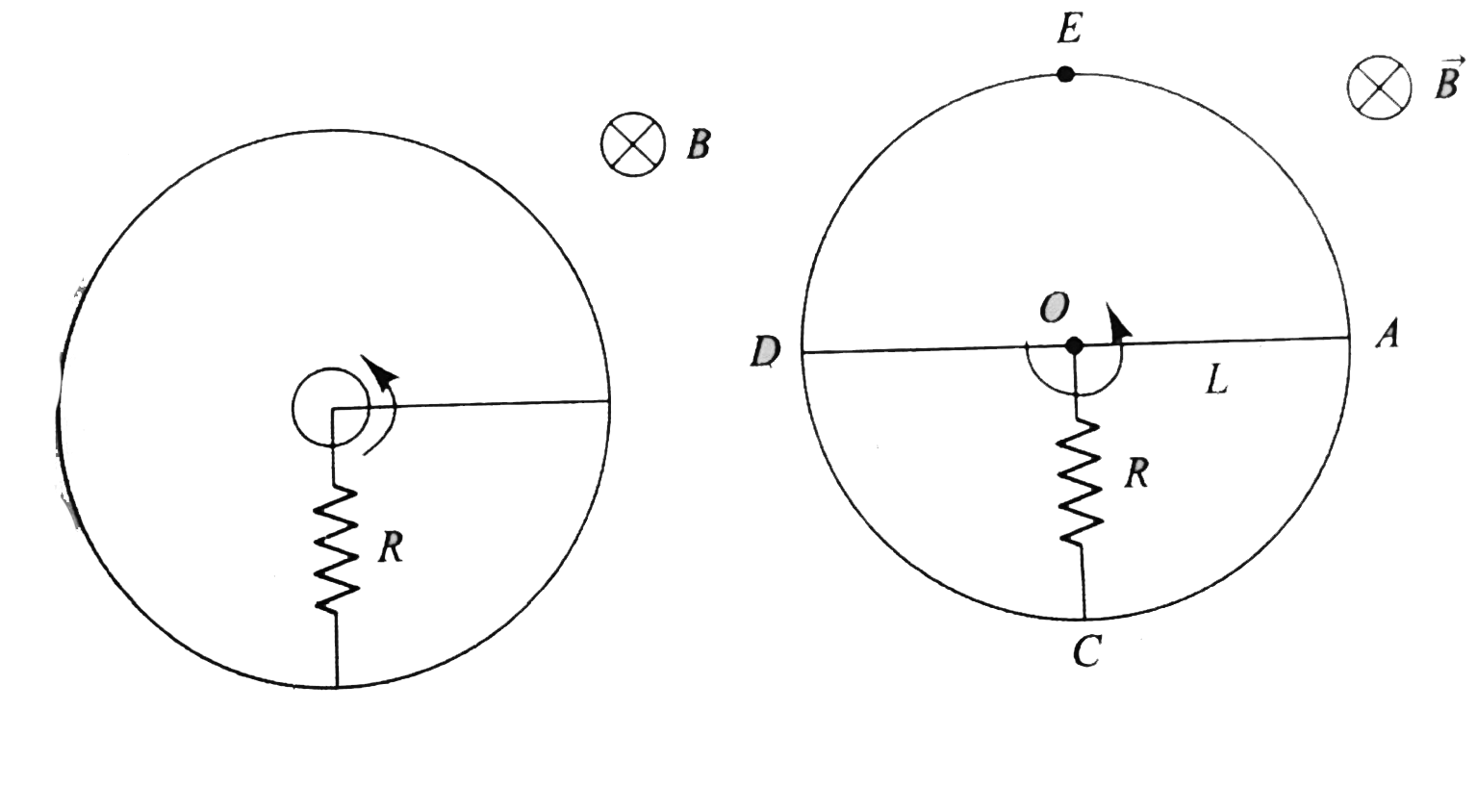 View Solution
Question 38
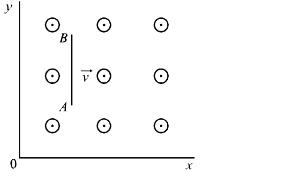
a conducting rod of length L=30.0cm movies in a magnetic field →B of magnitude 0.450T directed into the plane of the figure. The rod moves with speed v=5.00ms−1 in the direction shown.
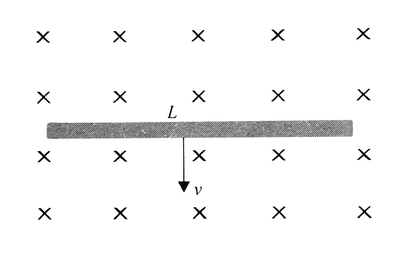
(a) What is motional emf inuced in the rod ?
(b) What is the potential difference between the ends of the rod?
( c) When point, aorb, is at higher potential?
(d) When the charges in the rod are in equilibrium, what are the magnitude and direction of the electric field within the rod?
(e) When the charges in the rod are in the rod in equilibrium, which point, aorb, has an excess of positive charge?View SolutionQuestion 39
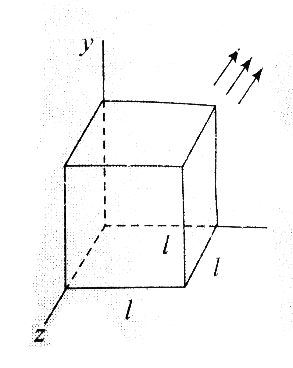
The cube shown in, 50.0cm on a side, is in a uniform magnetic field of 0.120T, directed along the positive y-axis. Wires A,C,andD move in the direction indicated, each with a speed of 0.350ms−1. (Wire A moves parallel to the x-y plane, C moves at an angle of 45.0∘ below the x-y plane, and D moves parallel to the x-z plane.) What is the potential difference between the ends of each wire?
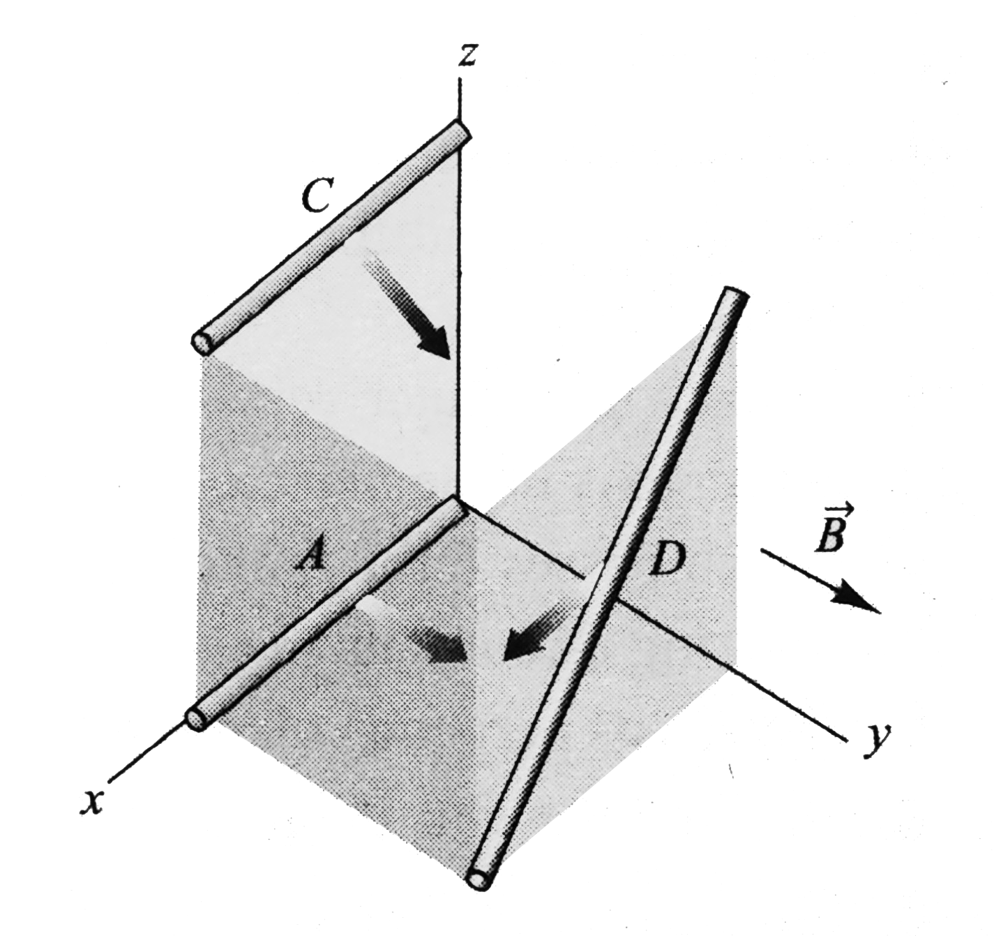 View Solution
Question 44
A wire is bent into three circular segment og radius r=10cm as shown in. Each segment is a quardrant of a circle ab lyinf in rthe x−y plane, bc lying in the y−z plane and ca lying in the z−x plane.
(a) if a magnetic field B points in the positive x direction, what is the magnitude of the emf developed in the wire when B increases at the rate of 3mTs−1?
(b) What is the direction of teh current in the segment bc.
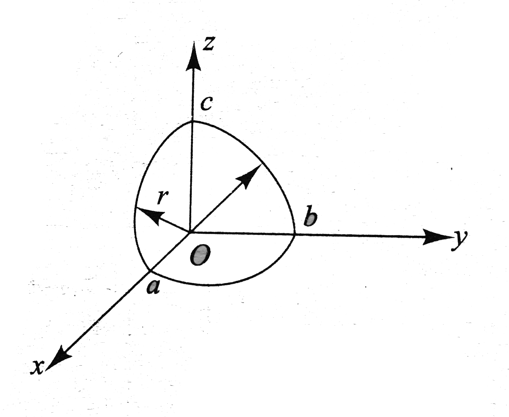 View Solution
Question 45
Three identical wires are bent into semi-circular arcs to each of radius R. These arcs are connected with each other to form a closed mesh such that one of tham lies in x−y plane, one in y−z plane and the other in z−x plane as shown in. In the region of space, a uniform magnetic field of induction →B=B0(ˆi+ˆj) exists, whose magnitude increases at a constant rate dB/dt=α. Calculate the magnitude of emf induced in the mesh and mark the direction of flow of induced current in the mesh.
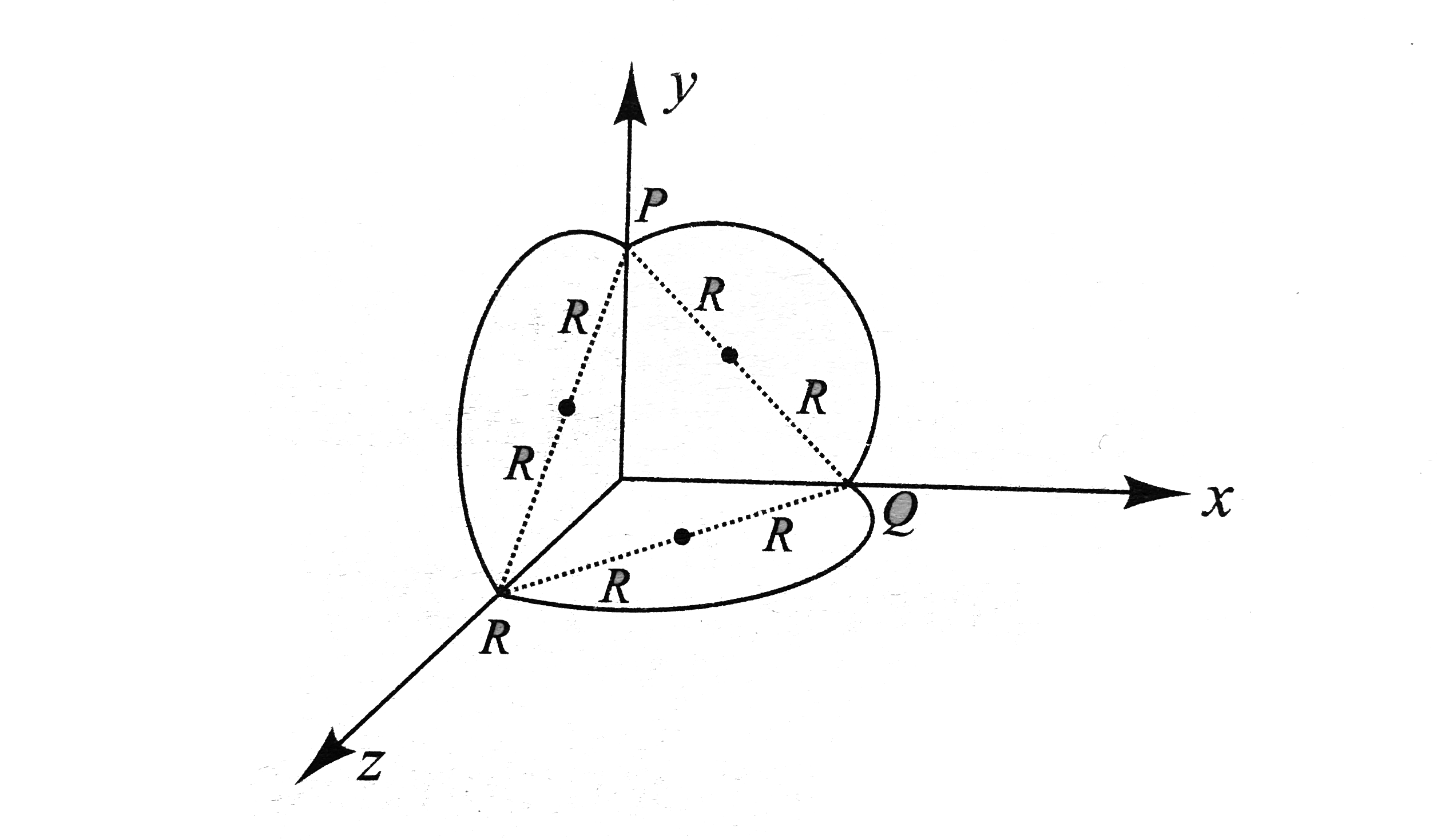 View Solution
Question 46
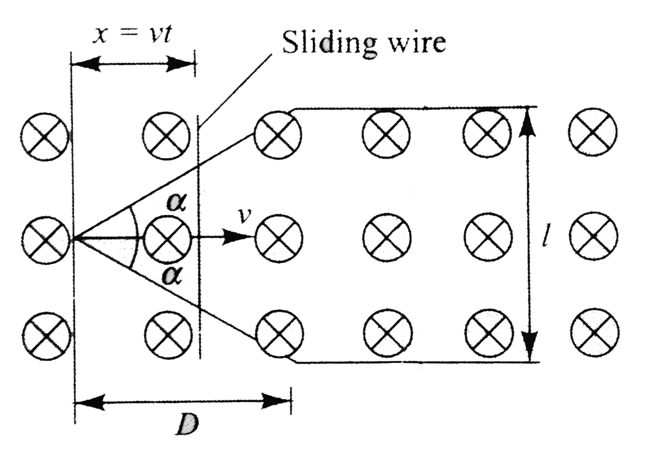
an electric circuit is component of the three conducting rods MO , ON and PQ , as shown in the figure. The resistence of the rods per unit length is λ . The rod PQ slide, as shown in the figure, at a constant velocity v , keeping its tilt angle relative to ON and MO fixed at 45∘ . At each instance the circuit is closed. The whole system is embedded in a uniform magnetic field B , which is directe dperpendicularly into th epage. Compute the time-dependent induced electric current View Solution
Question 47
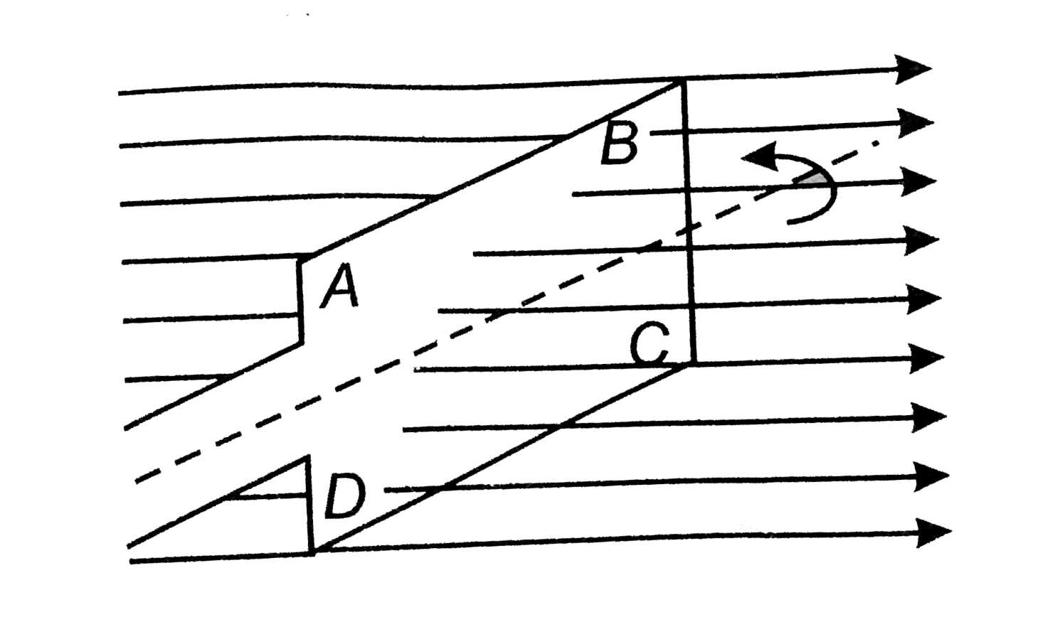
The wire loop, shown in , is made by taking a flat rectangular loop of sides 10cm and 20cm bending at the long sides a their midpoints to produce two mutually perpendicular square parts. The loop is laced in an oscillating magnetic field B=B0sin2πvt, with B0=1.2×10⁻³T and v=60Hz. The magnetic field is induced at angle θ with x−z plane.
(a) Express the emf around the loop as a function of time and the angle θ.
(b) For what angle θ does the induced emf have the largest amplitude ?
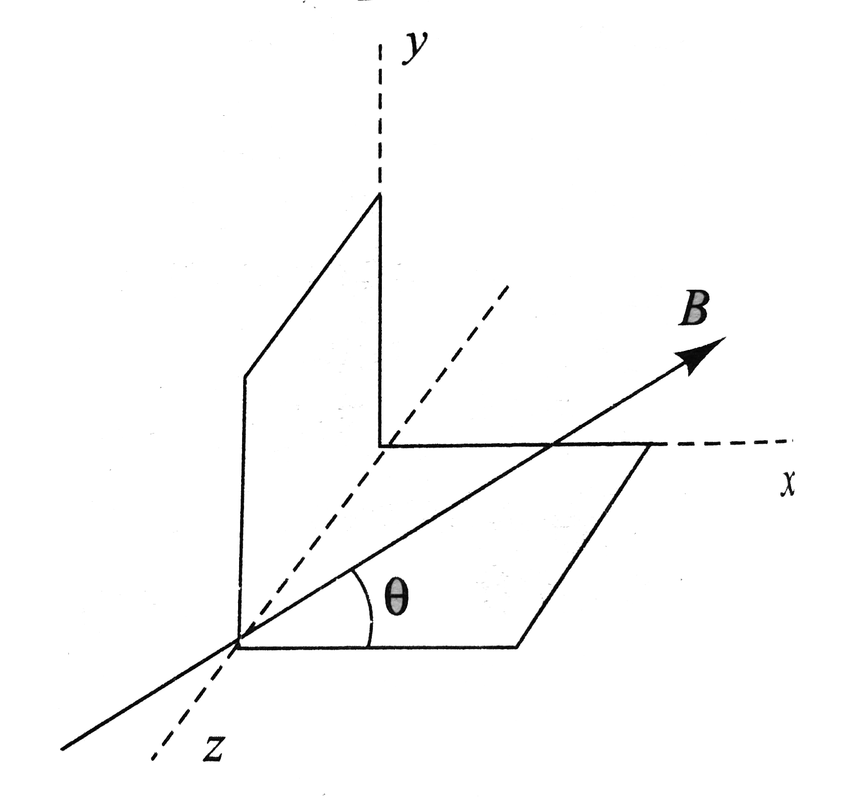 View Solution
Question 48
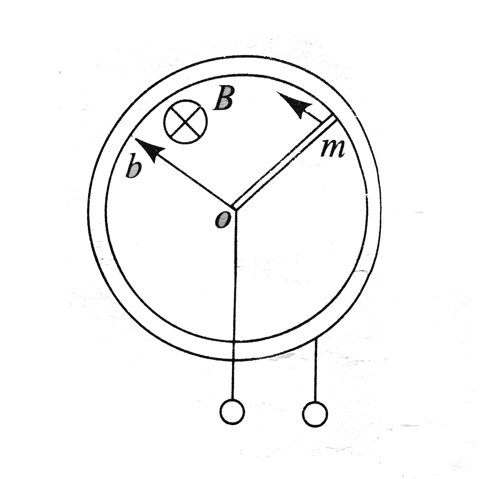
A rod of mass m can rotate without friction about axis sliding (also without friction) along a conducting ring of radius b arranged in a vertical plane as shown in the . The entire arrengement is placed in a uniform magnetic field with the inducetion B perpendicular to the plane of the ring. The axis and the conductor are connected to teh terminals of a current source. Determine
(a) according to which law current I flowing in the rod must vary for the rod to rotate at a constant angular speed. Being to measure the time from the instant when the rod is in its right-hand horizontal position. Consider the current to be positive when it flows from the axis of rotation toward the ring.
(b) what emf E of the source must be applied to maintain the required current? Consider the total resistance of the circuit to be constant and equal to R. Disergard the inductance of teh circuit.
 View Solution
Question 49
A square shaped, conducting wire loop of side L, total mass m and total resistance R initially lies in the horizontal x−y plane, with corners at (x,y,z)=(0,0,0),(0,L,0),(L,0,0),and(L,L,0). There is a uniform upward magnetic field in the space within and around the loop. The side of the loop that extends from (0,0,0)→(L,0,0) is held in place on the x-axis, the rest of the loop is released, it begins to rotate due to the gravitational torque.
(a) Find the net torque (magnitude and direction)that acts on the loop when it has rotated through an anglr ϕ from its original orientation and is rotating dounward at an angular speed ω.
(b) Find the angular acceleration of the loop at the instant described in part (a).
( c) Compared to teh case with zero magnetic field, does it take the loop a longer or shorter time to rotate through 90∘ ? Explain.
(d) Is mechanical energy conserved as the loop rotates downward ? Explain. View SolutionQuestion 50
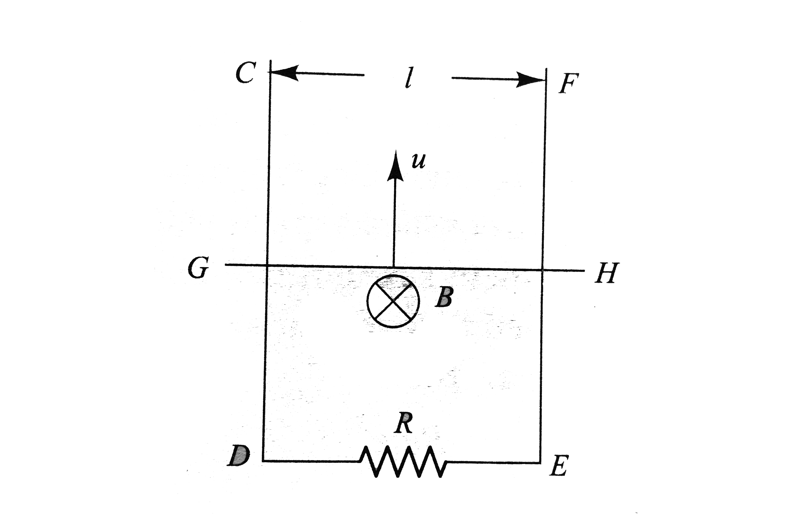
CDEF is a fixed conducting smooth frame in vertical plane. A conducting uniform rod GH of mass m can move vertically and smoothly without losing contact with the frame. Gh always remains horizontal and is given velocity u upward and released. Taking the acceleration due to gravity as g and present other than R. Find out the time tasken by the rod to reach the highest point.
 View Solution
Question 51
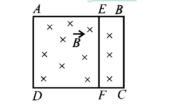
A rectangular frame ABCD, made of a uniform metal wire, has a straight connection between E and F made of the samae wire, as shown in fig. AEFD is a square of side 1m, and EB=FC=0.5m. The entire circuit is placed in steadily increasing, uniform magnetic field directed into the plane of the paper and normal to it. The rate of change of the magnetic field is 1T/s. The resistance per unit length of the wire is 1ω/m. Find the magnitude and directions of the currents in the segments AE, BE and EF.
 View Solution
Question 52
Two fixed long straight wires carry the same current i in opposite directions as shown in . A square loop of side b is fixed in the plane of the wires with its length parallel to one wire at a distance a shown in the figure.
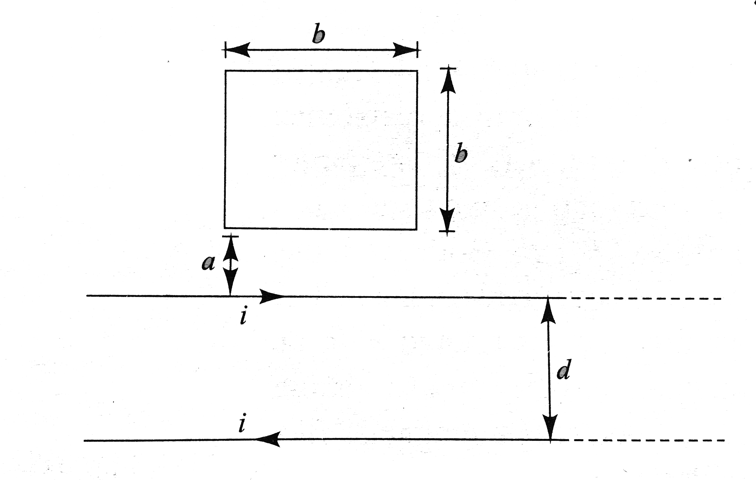
(a) alculate at the induced emf in the loop if the current in both the wires is changing at the rate di/dt.
(b) What is the direction of force on the loop if di/dt is positive?View SolutionQuestion 53
Two parallel, long, straight conductor lie on a smooth plane surface. Two other parallel so as to form a square of side a initially. A uniform magnetic field B exists at right angles to the plane containing the cinductors. Now they start moving out with a constant velocity v.
(A) Will the induced emf be time dependent?
(b) Will the current be time dependent ? View SolutionQuestion 54
The rectangualr wire- frame, shown in has a width d, mass m, resistance R and a large length. A uniform magnetic field B exists to the left of the frame. A constant force F starts pushing the frame into the magnetic field at t =0. (a) Find the acceleration of the frame when its speed has increased to v. (b) Show that after some time the frame will move with a constant velocity till the whole frame enters into the magnetic field. find this velocity v0. (c) show that the velocity at tiem t is given by v=v0(1−e−Ftmv0).
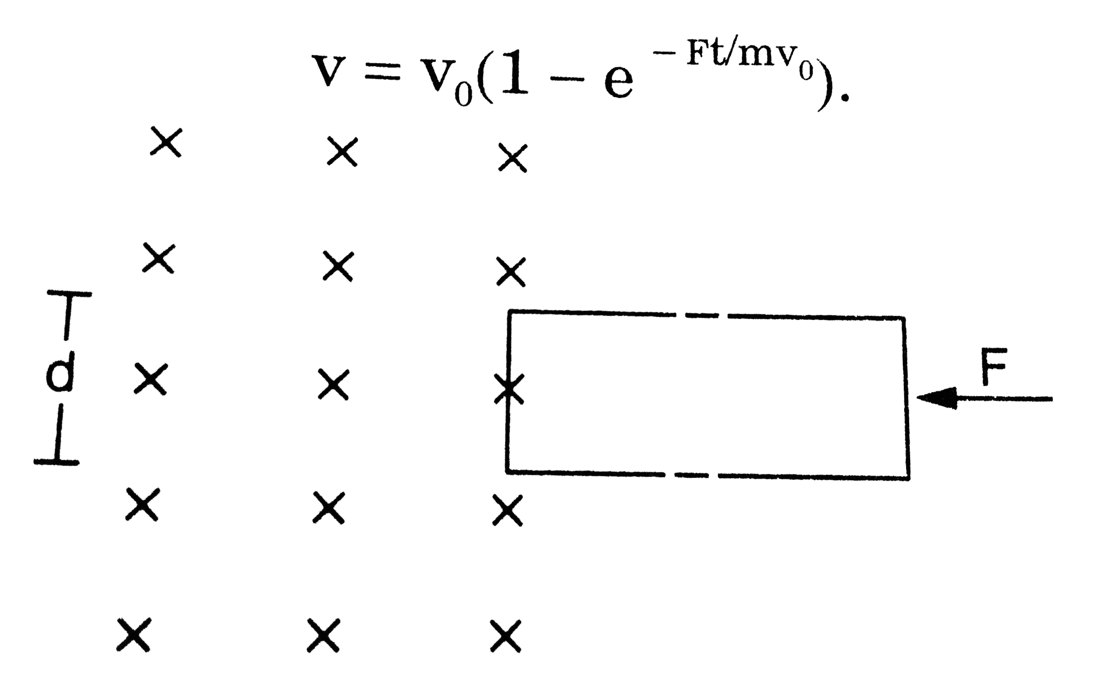 View Solution
Question 55
, ABCEFGA is a square conducting frame of side 2m and resistance 1Ωm−1. A uniform magnetic field b is applied perpendicular to the plane and pointing inward. It increases with time at a constant rate of 10Ts−1. Find the rate at which heat is produced in the circuit, AB=BC=CD=BH.
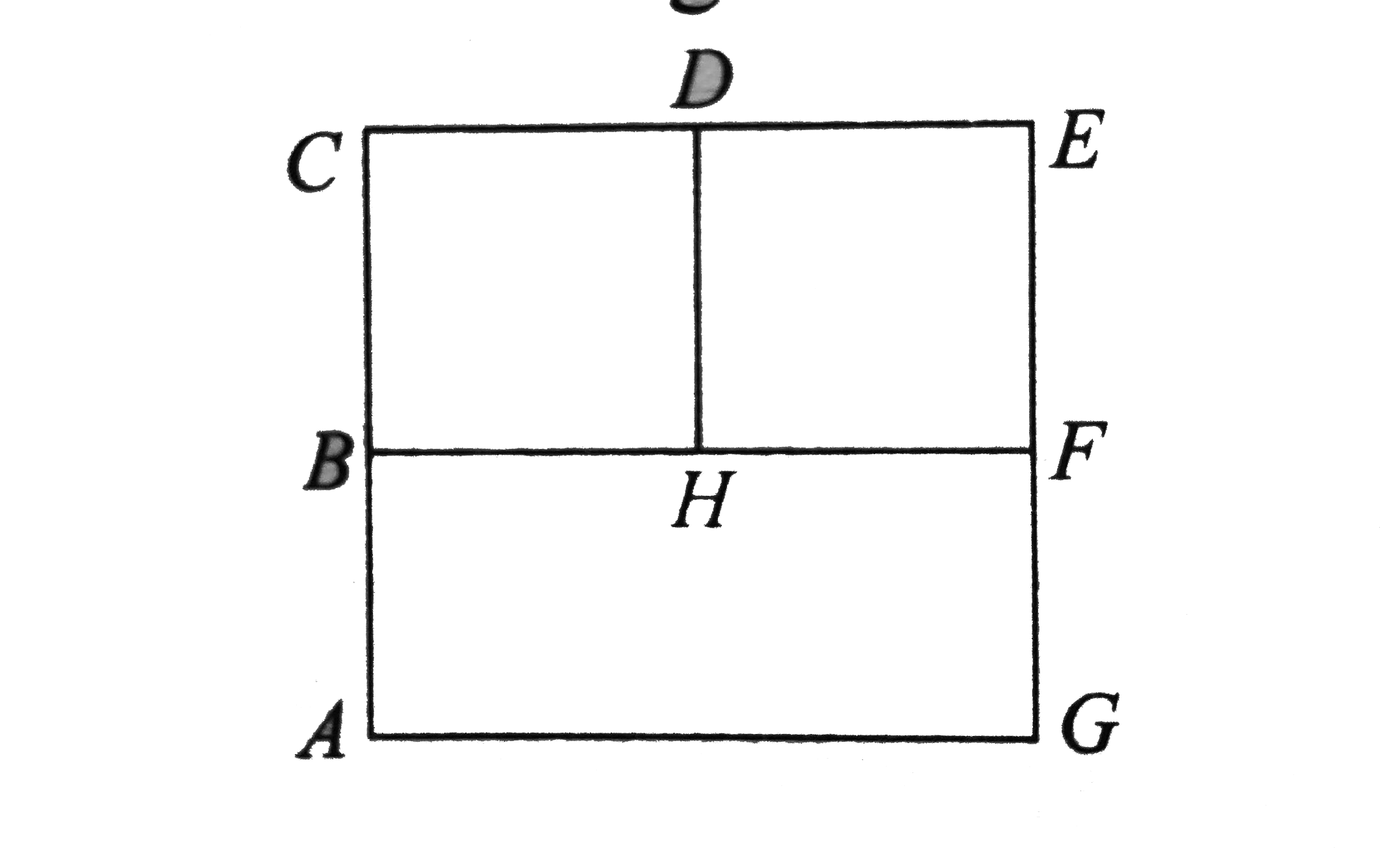 View Solution
Question 61
A thin circular ring of area A is held perpendicular to a uniform magnetic field of induction B. A small cut is made in the ring and a galvanometer is connected across the ends such that the total resistance of the circuit is R. When the ring is suddenly squeezed to zero area, the charge flowing through the galvanometer is View SolutionQuestion 67
The linear loop has an area of 5×10⁻⁴m2 and a resistance of 2Ω. The larger circular loop is fixed and has a radius of 0.1m. Both the loops are concentric and co-planner. The smaller loop is rotated with an angular velocity ωrads−1 about its dismeter. The magnetic flux with the smaller loop is
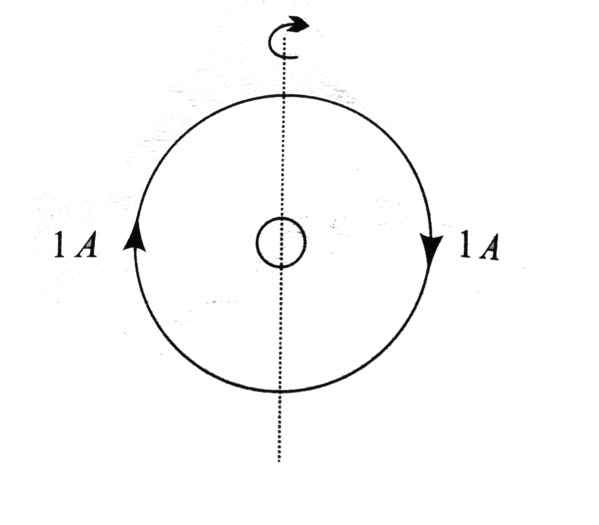 View Solution
Question 68
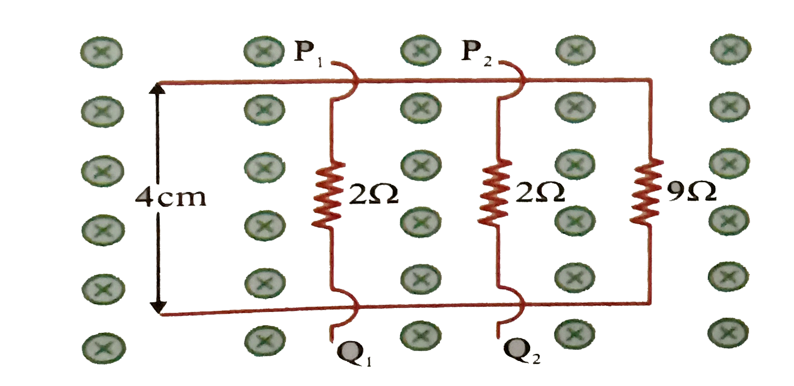
A circuit ABCD is held perpendicular to the uinform magnetic field of B=5×10⁻²T extending over the region PQRS and directed into the plane of the paper. The cicuit is moving out of the field at a uin form speed of 0.2ms−1 for 1.5s. During this time, the current in the 5Ω resistor is
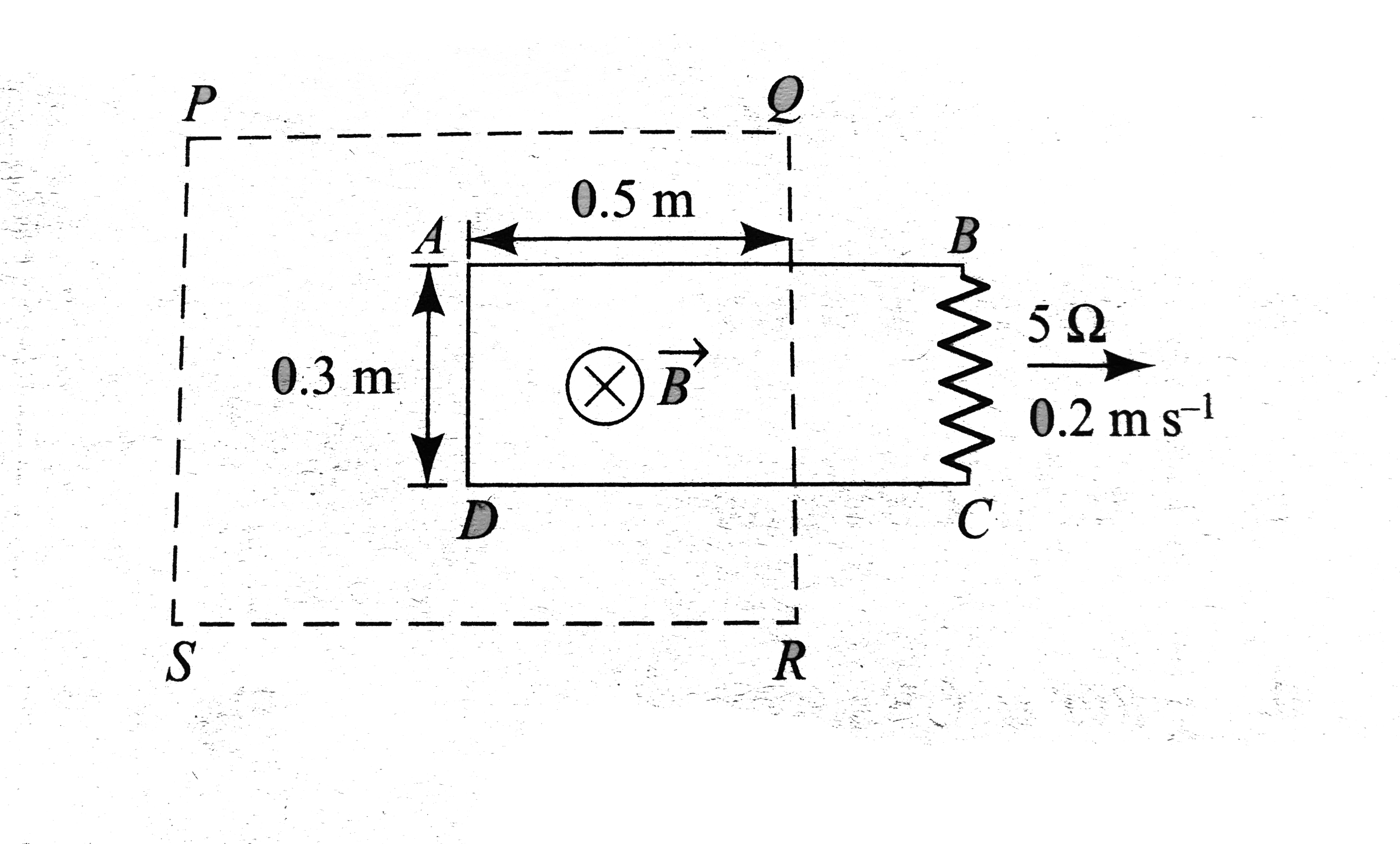 View Solution
Question 69
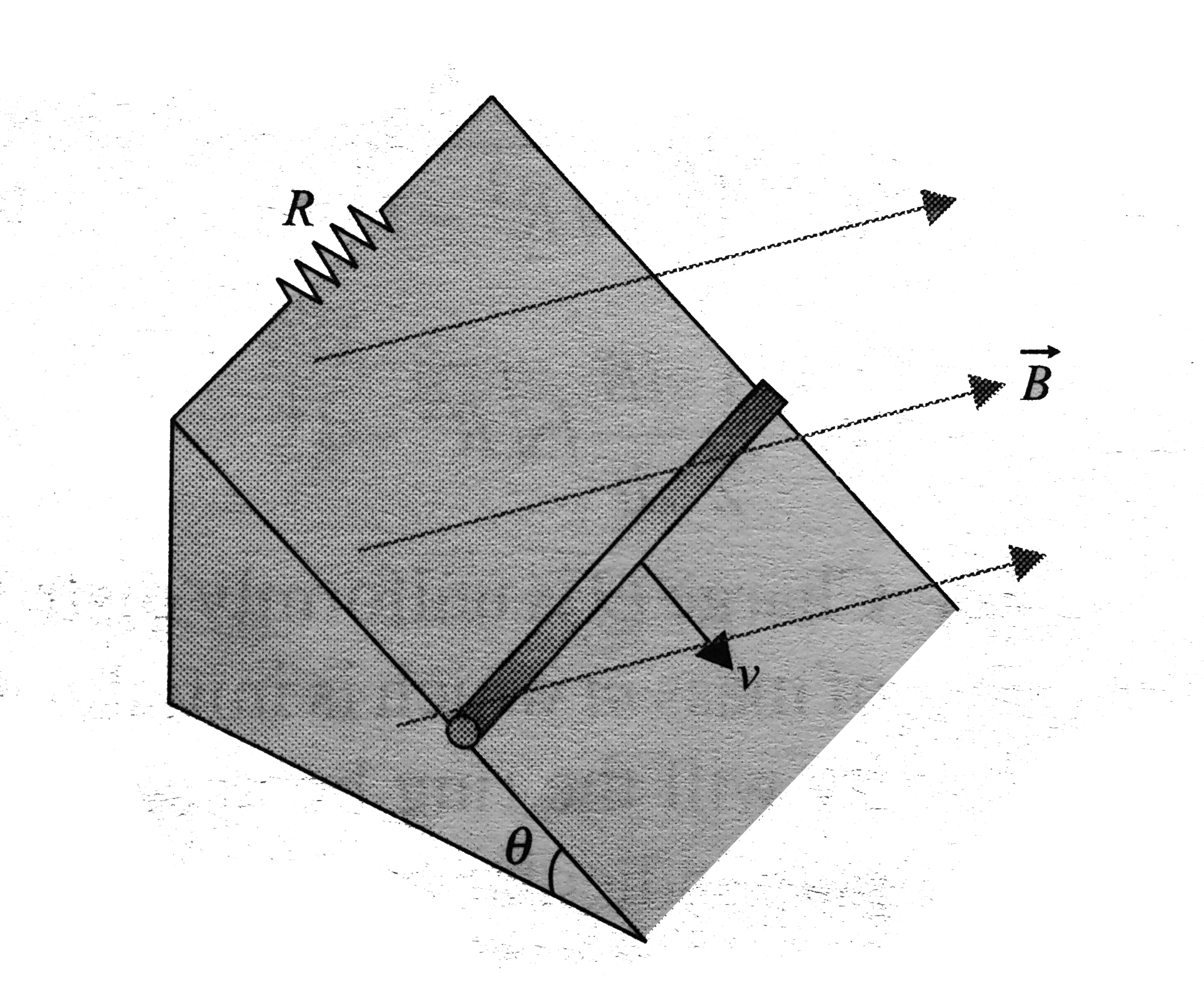
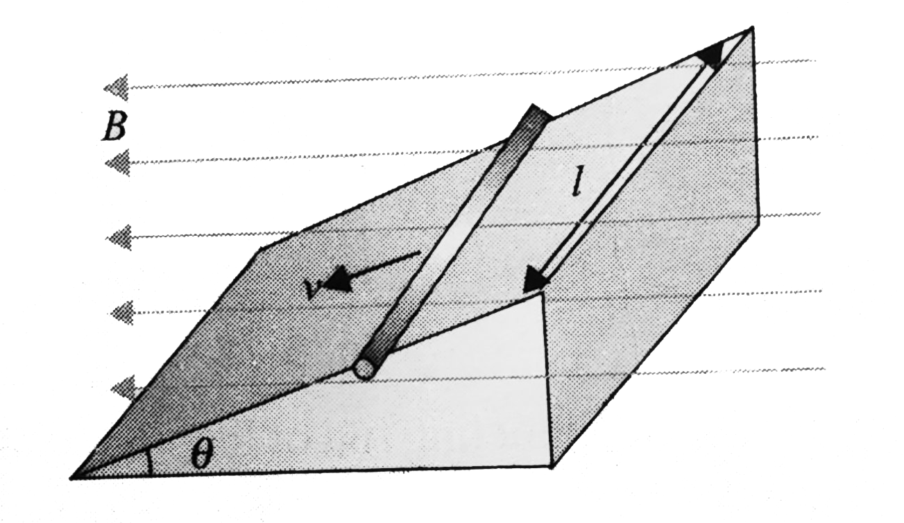
a conducting wire os mass m slides down two smooth conducting bars, set at an angle θ to the horizontal as shown in . The separatin between the bars is l. The system is located in the magnetic field B, perpendicular to the plane of the sliding wire and bars. The constant velocity of the wire is
 View Solution
Question 71
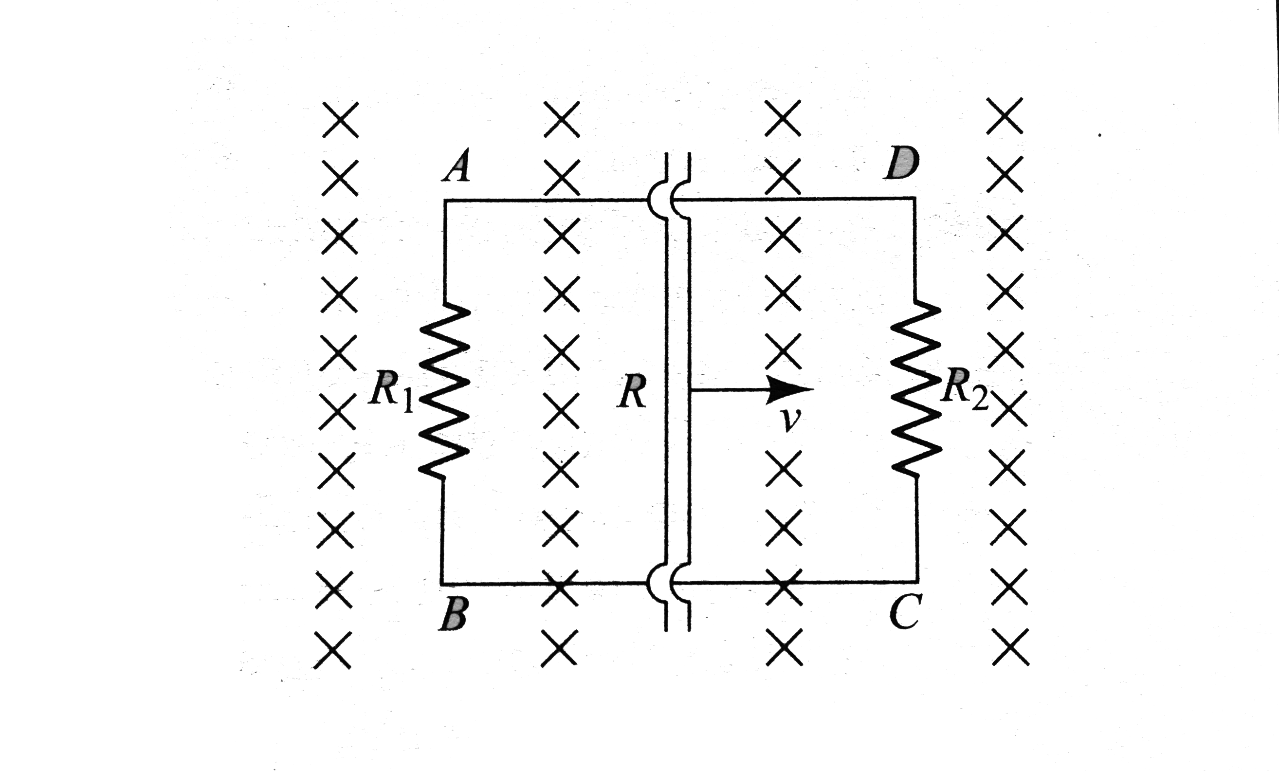
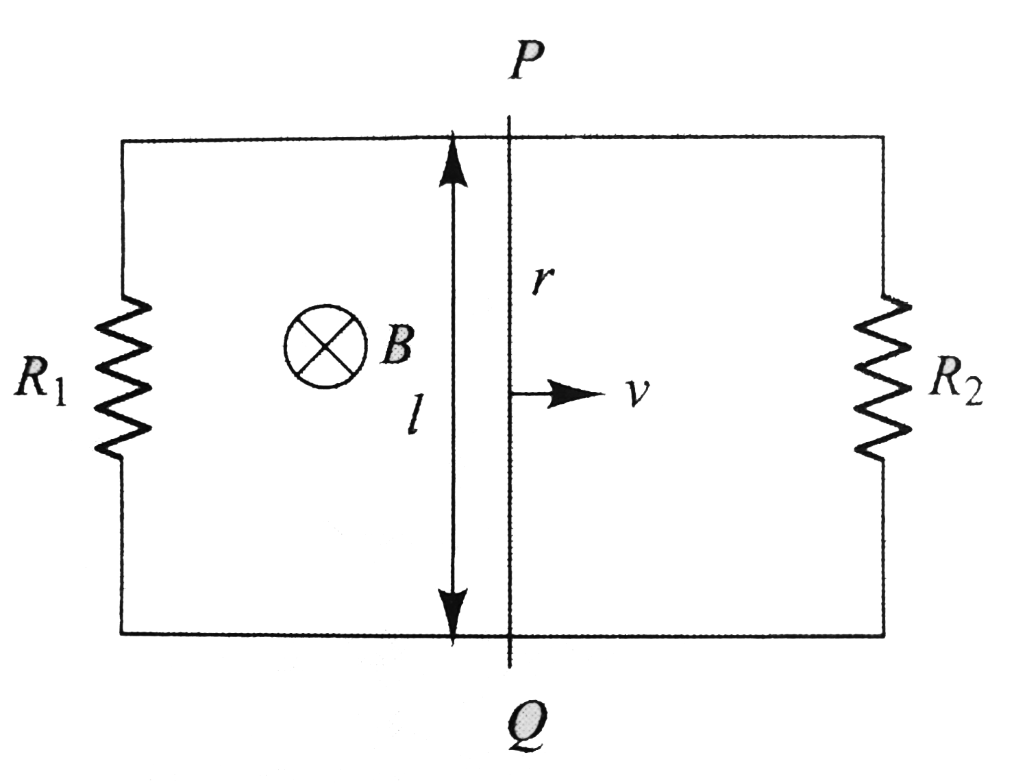
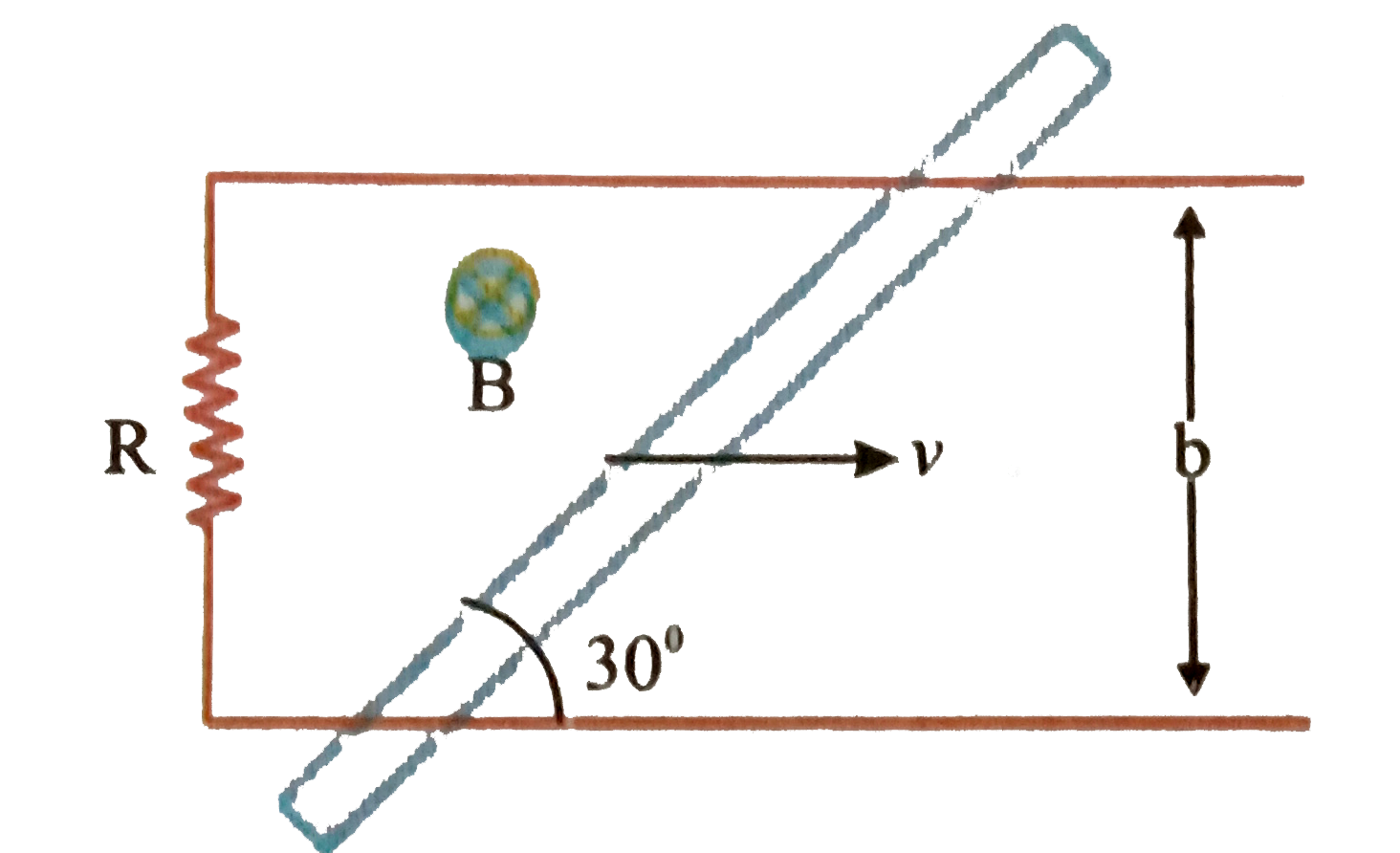
A rectangular loop with a sliding conductor of length l is located in a uniform magnetic field perpendicular to the plane of the loop . The magneitc inducetion is b. The resistances R1 and R2, respectively. Find the current through the conductor during its motion to the right with a constant velocity v.
 View Solution
Question 72
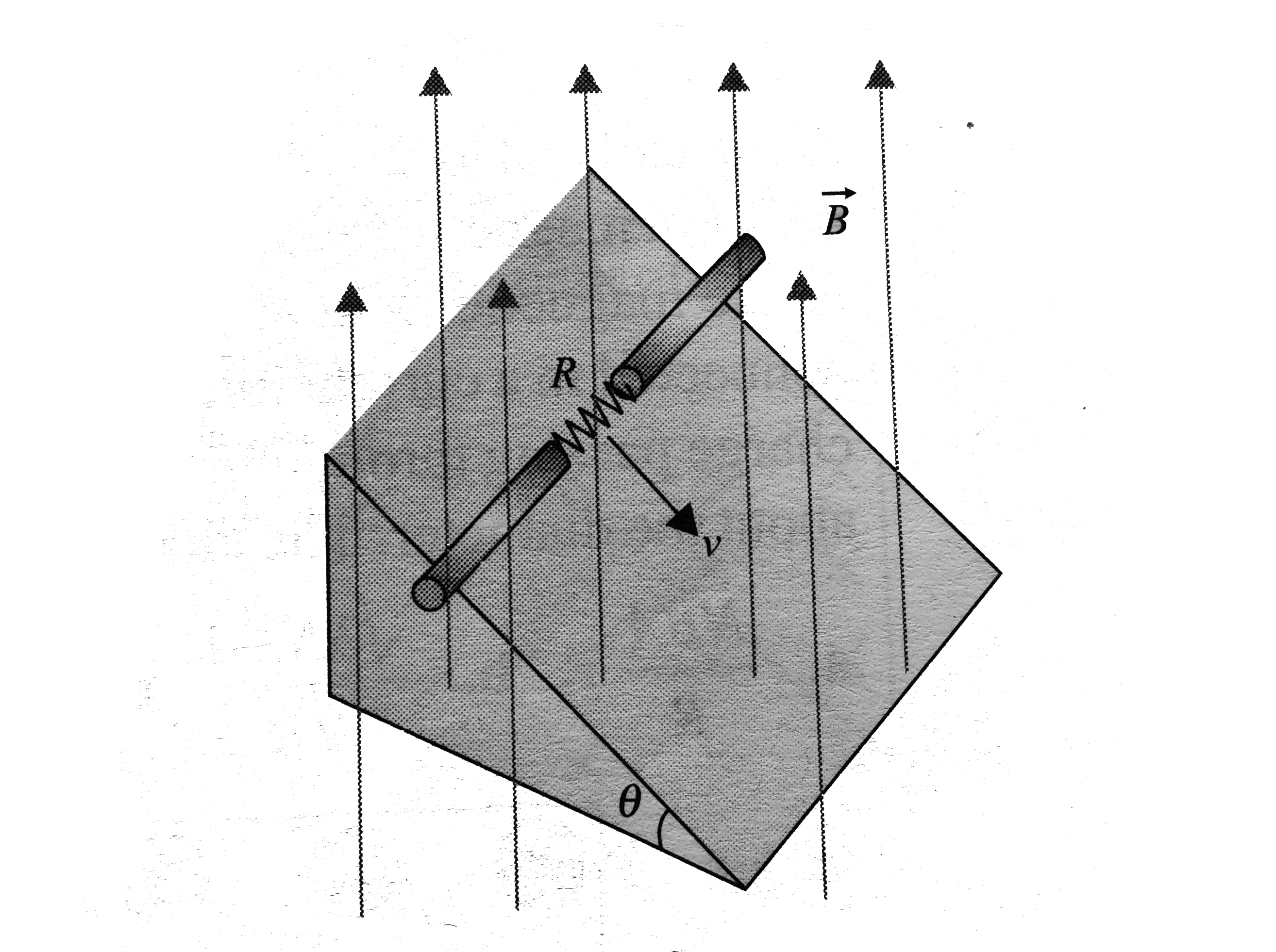
A wire of length l, mass m and resistance R slides without any friction down the parallel conducting rails of negligible resistance . The rails are connected to each other at the bottom by a resistanceless rail parallel to the wire so that the wire and the rails form a closed rectangualr conducting loop. The plane of the rails makes an angle θ with the horizontal and a uniform vertical magnetic field of the inducetion B exists throughout the rregion. Find the steady state velocity of the wire.
 View Solution
Question 73
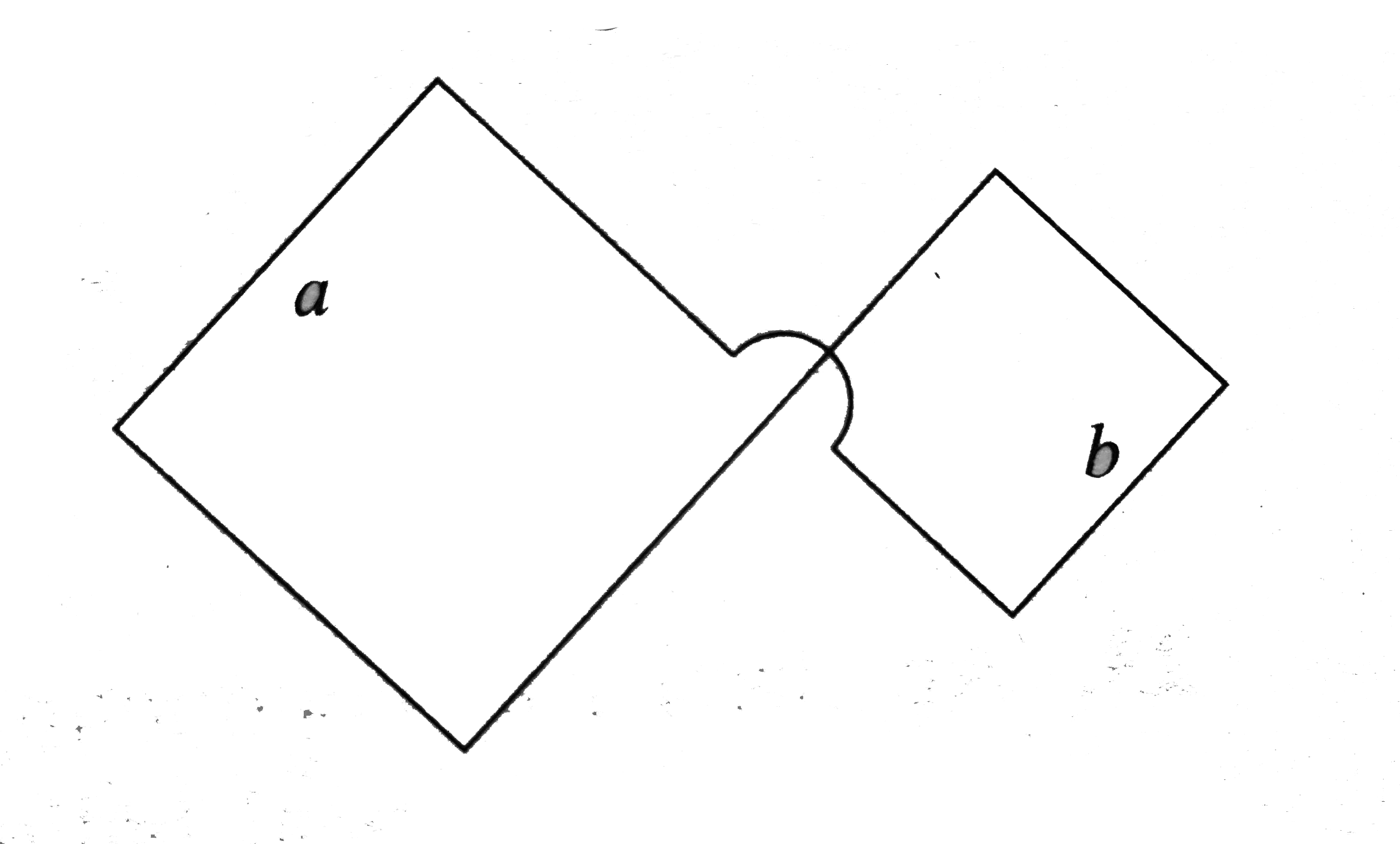
A plane loop, shaped as two squares of sides a=1m and b=0.4m is introduced into a uniform magnetic field ⊥ to the plane of loop . The magnetic field varies as B=10(−3)sin(100t)T. The qamplitude of the current induced in the loop if its resistance per unit length is r=5mΩm−1 is
 View Solution
Question 75
A rectangular loop of sides 10cm and 5cm with a cut is stationary between the pole pieces of an electromagnet. The amgnetic field of the magnet is normal to the loop. The current feeding the electromagnet is reduced so that the field decreases from its initial value of 3.0T at the rate of 0.02Ts−1. If the cut is joined and the loop has a resistance of 2.0Ω, the power dissipated by the loop as heat is View SolutionQuestion 77
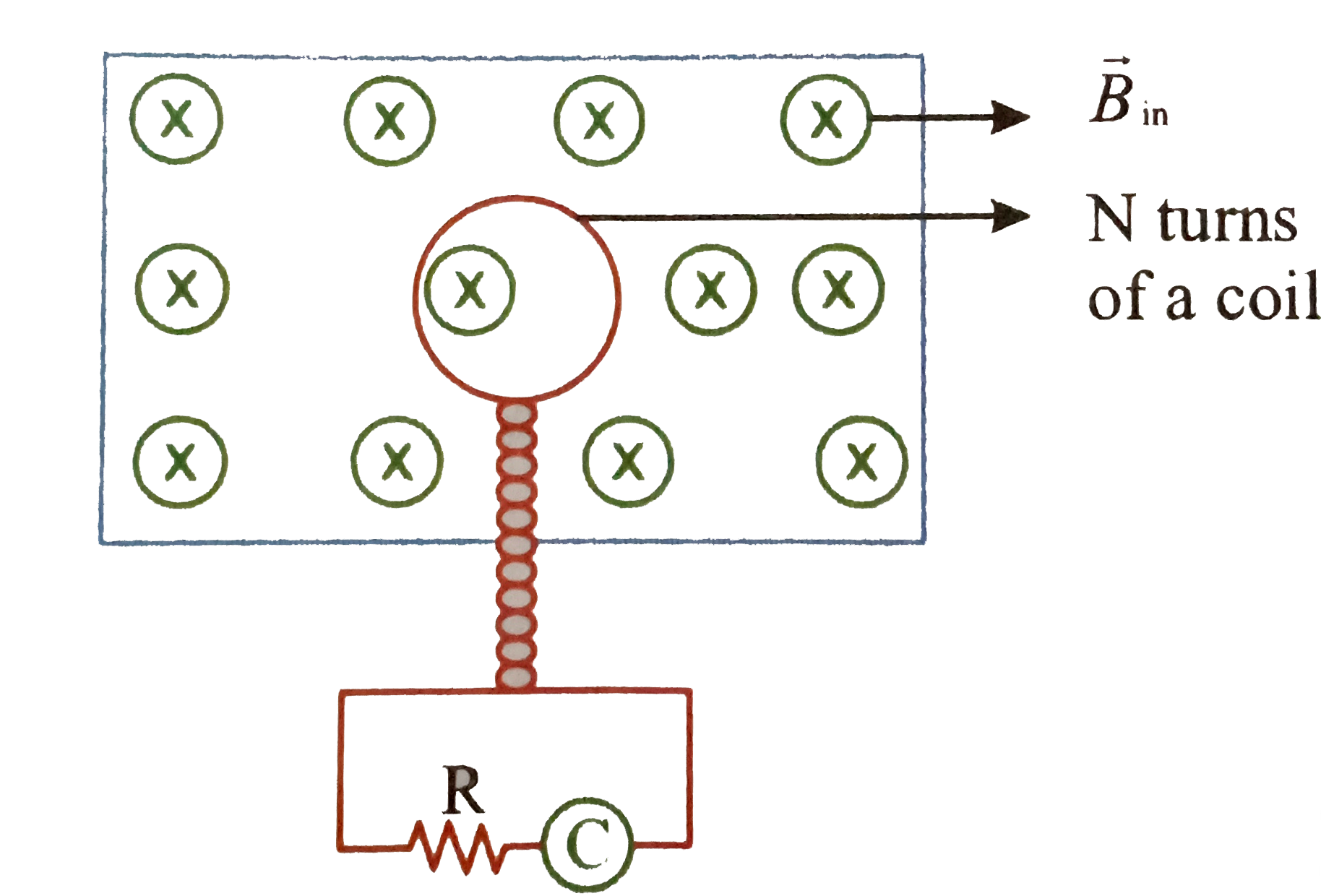
A flip coil consits of N turns of circular coils which lie in a uniform magnetic field. Plane of the coils is perpendicular to the magnetic field as shown in figure. The coil is connected to a current integrator which measures the total charge passing through it. The coil is turned through 180∘ about the diameter. The charge passing through the coil is
 View Solution
Question 78
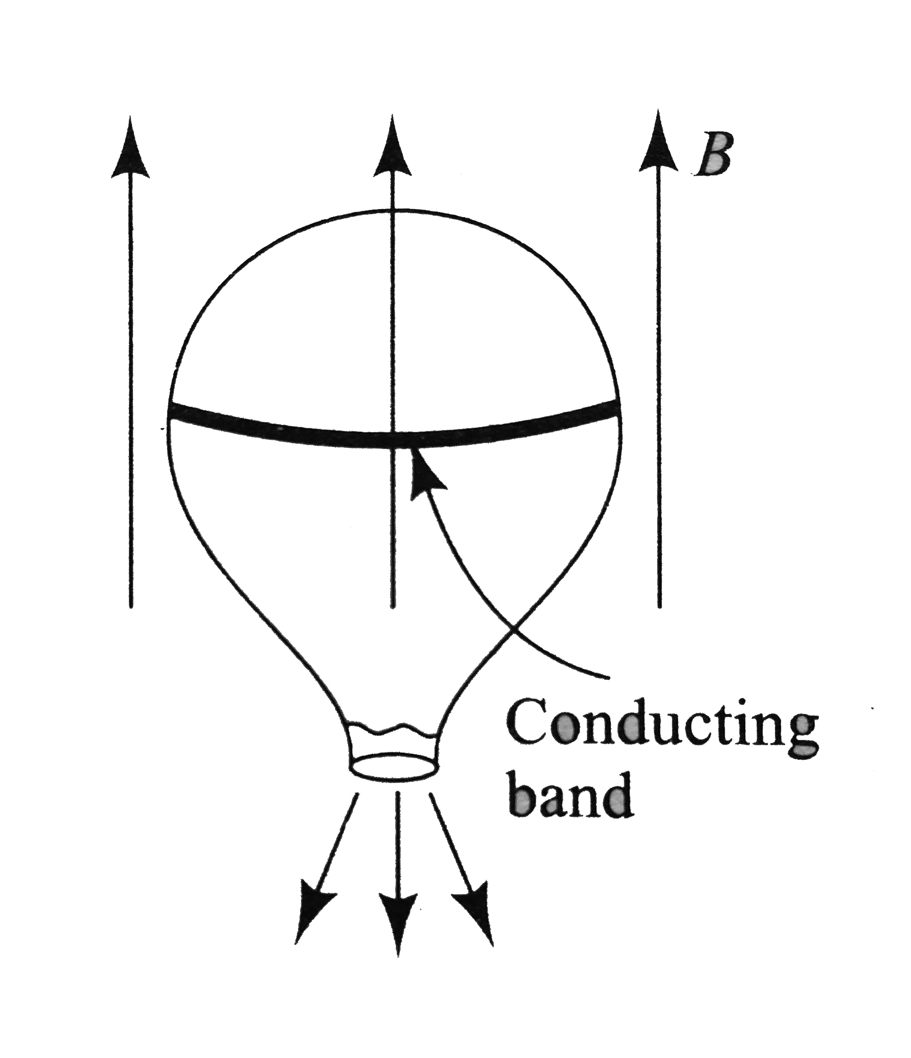
An elasticized conducting band is around a spherical ballon . Its plane through the center of the balloon. A uniform nmagnetic field of magnitude 0.04T is directed perpendicular to the plane of the band. Air is let out of the balloon at 100cm3s−1 at an instant when the radius of the balloon is 10cm. The induced emf in the band is
 View Solution
Question 79
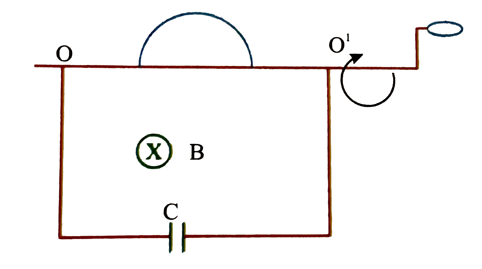
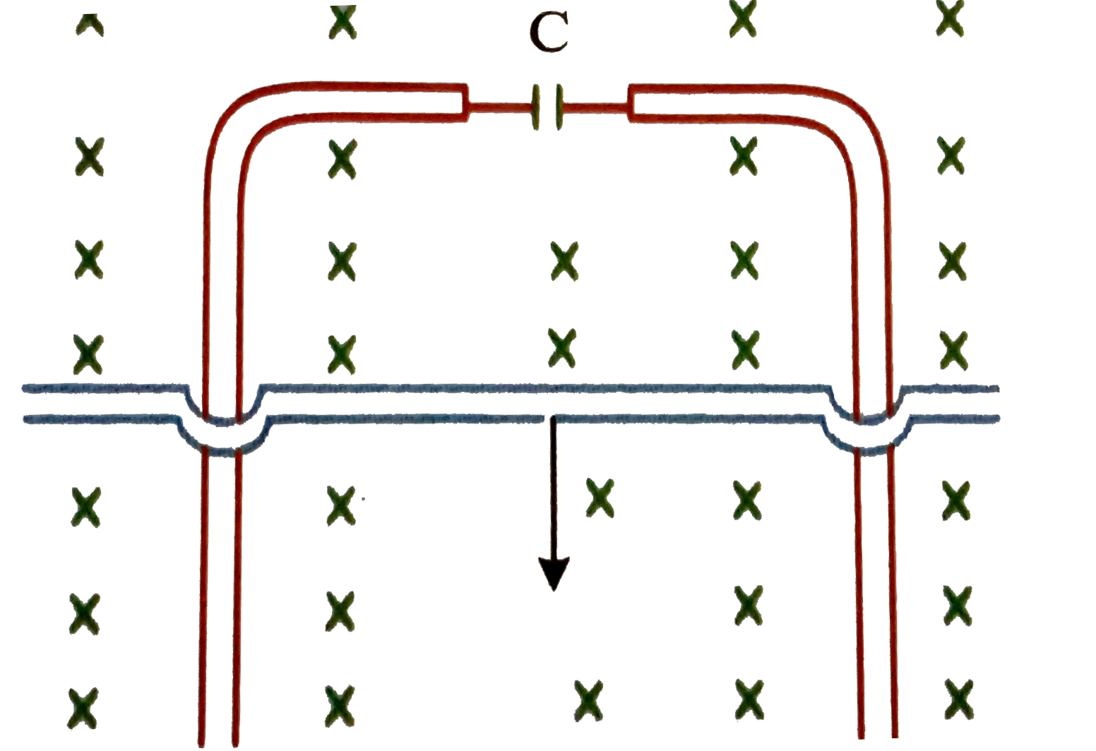
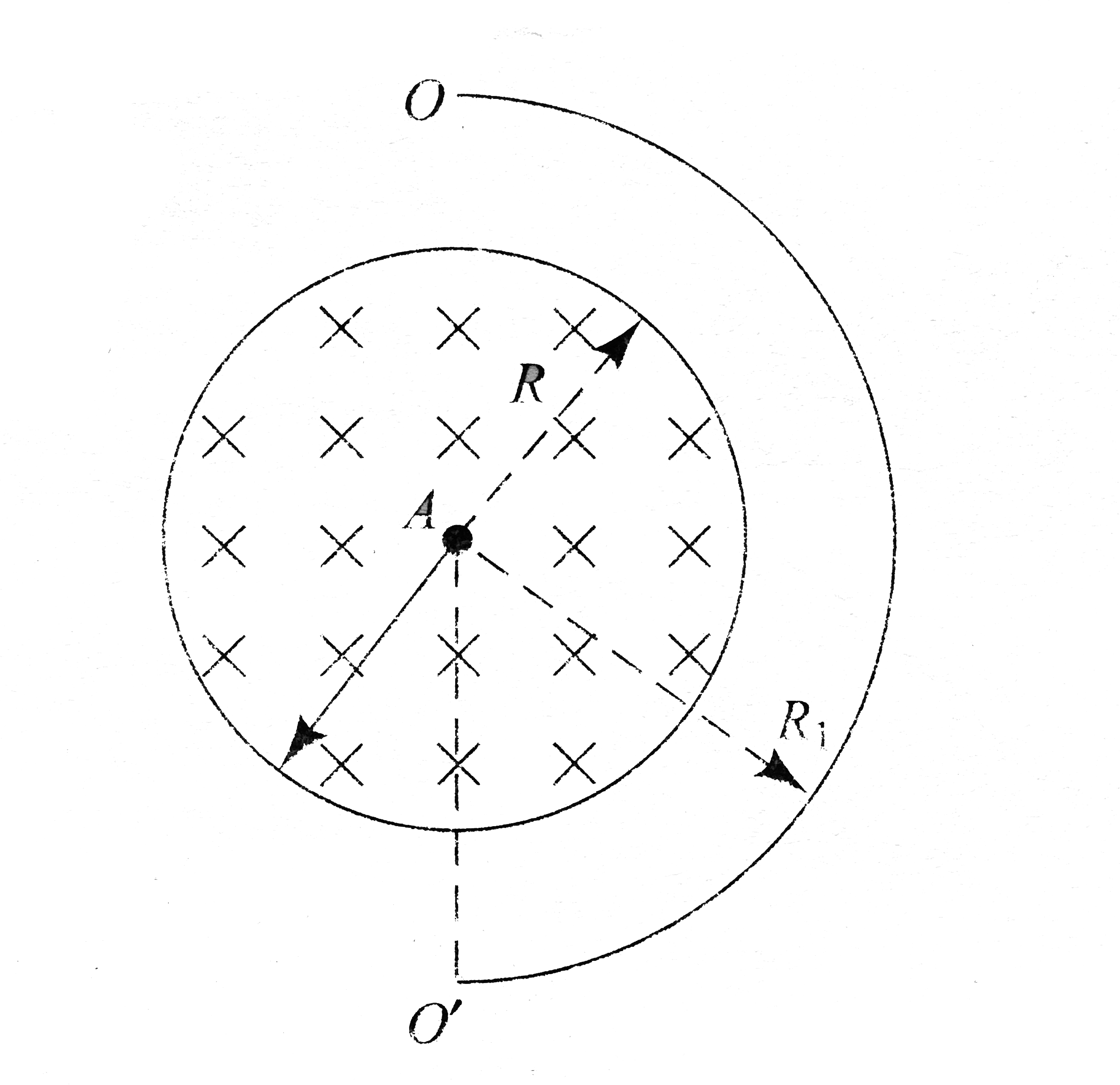
A copper rod is bent inot a semi-circle of radius a and at ends straight parts are bent along diameter of the semi-circle and are passed through fixed, smooth and conducting ring O and O' as shown in figure. A capacitor having capacitance C is connected to the rings. The system is located in a uniform magnetic field of induction B such that axis of rotation OO' is perpendicular to the field direction. At initial moment of time (t=0), plane of semi-circle was normal to the field direction and the semi-circle is set in rotation with constant angular velocity ω. Neglect the resistance and inductance of the circuit. The current flowing through the circuit as function of time is
 View Solution
Question 82
A vertical ring of radius r and resistance on R falls vertically. It is in contact with two vertical rails which are joined at the top. The rails are without friction and resistance. There is a horizontal uniform, magnetic field of magnitude B perpendicular to the plane of the ring and the rails. When the speed of the ring is v , the current in the section PQ is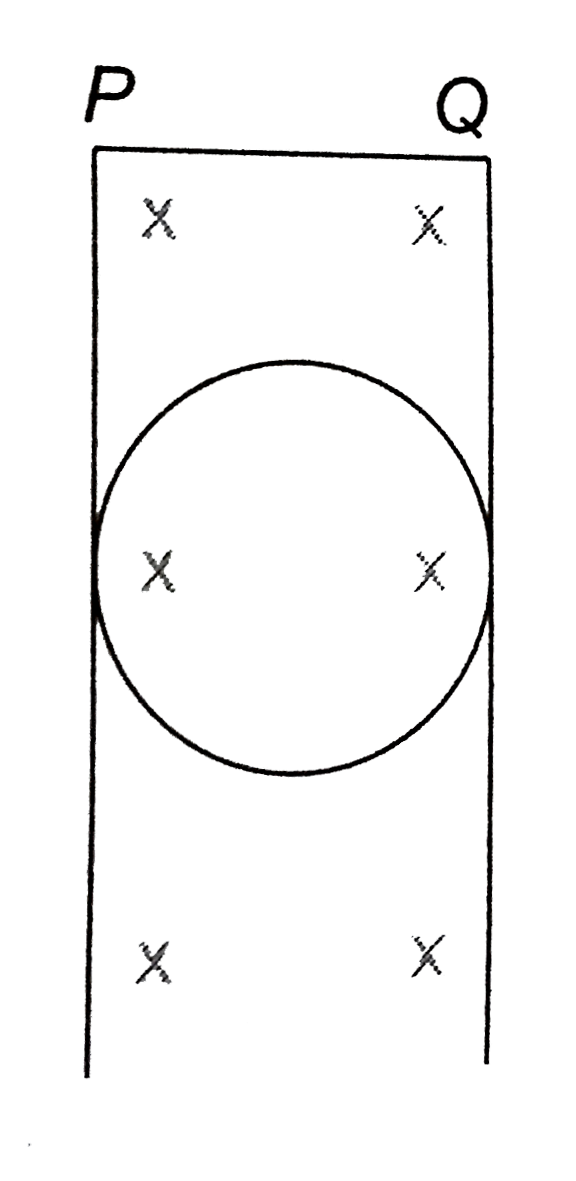 View Solution
Question 83
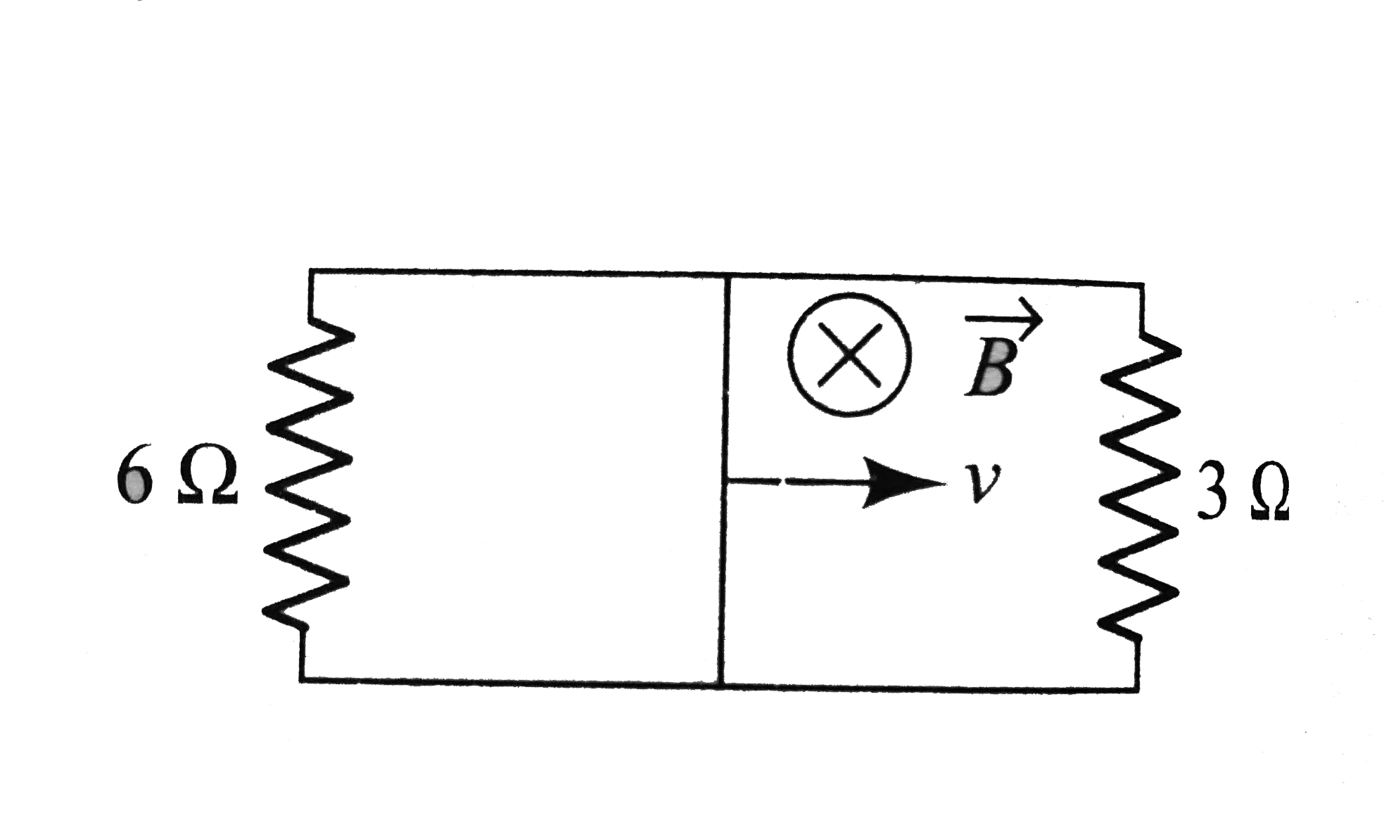
A rectangular loop with a sliding connector of length l=1.0m is situated in a uniform magnetic field B=2T perpendicular to the plane of loop. Resistance of connector is r=2Ω. Two resistances of 6Ω and 3Ω are connected as shown in . The external force required to keep the connetor moving with a constant velocity v=2ms−1 is
 View Solution
Question 84
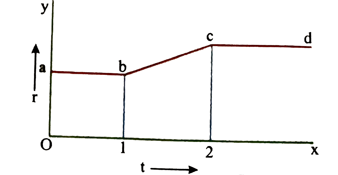
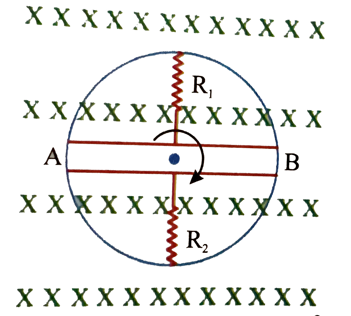
A metal rod of resistance 20Ω is fixed along a diameter of a conducting ring of radius 0.1m and lies on x−y plane. There is a magnetic field →B=(50T)→k. The ring rotates with an angular velocity ω=20rads−1 about its axis. An external resistance of 10Ω is connected across the center of the ring and rim. The current external resistance is View SolutionQuestion 91
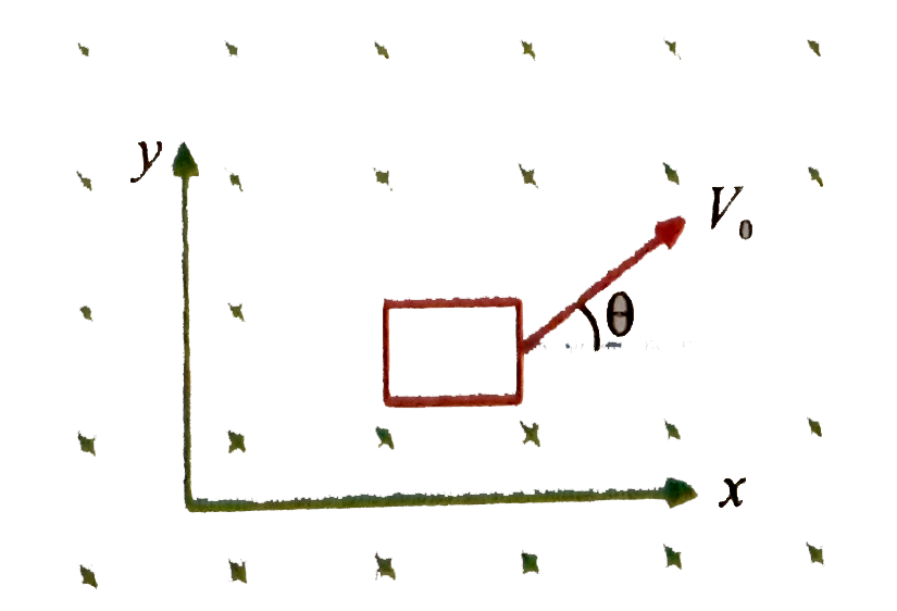
An equilateral triangular loop ADC having some resistance is pulled with a constant velocity v out of a uniform magnetic field directed inot the paper. At time t=0, side DC of the loop at is at edge of the magnetic field.
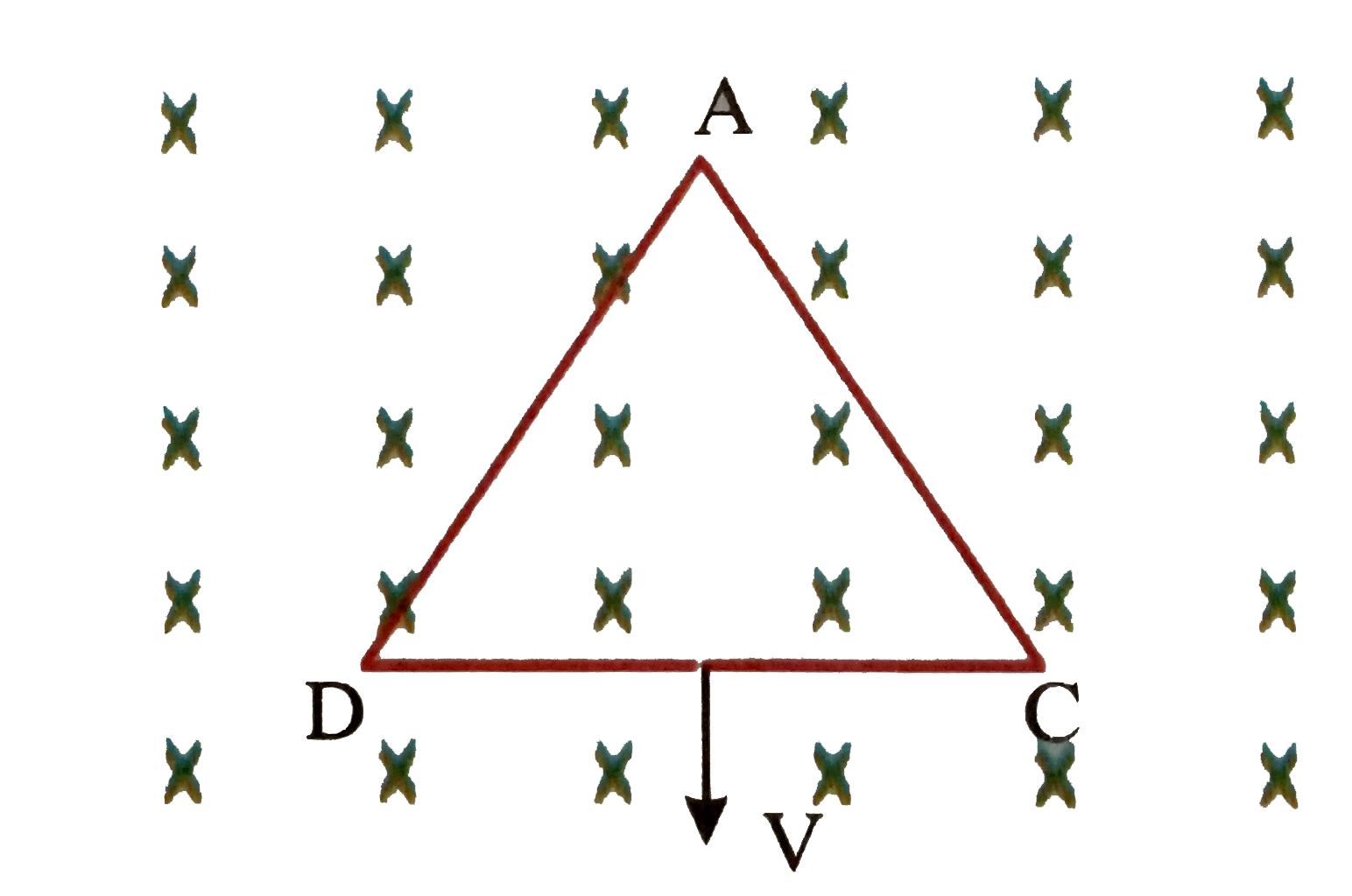
The induced current (i) versus time (t) graph will be asView SolutionQuestion 93
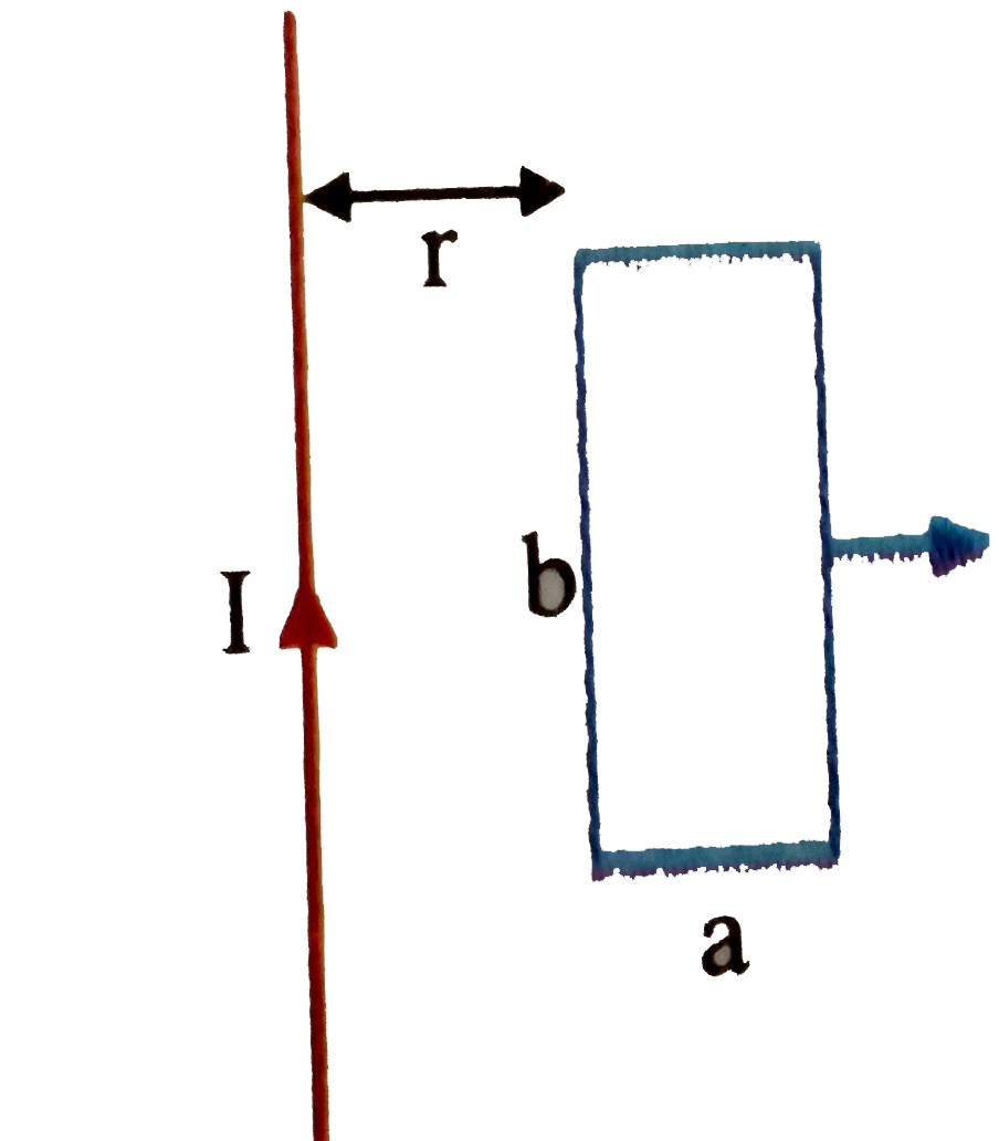
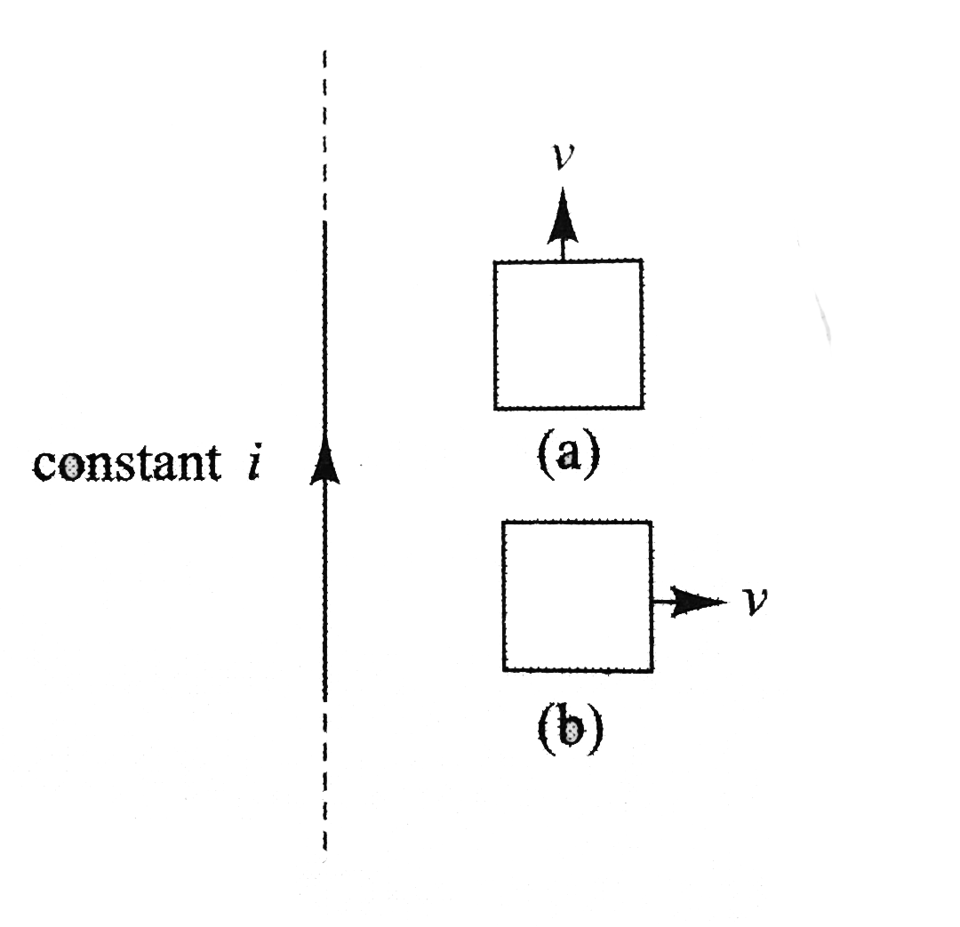
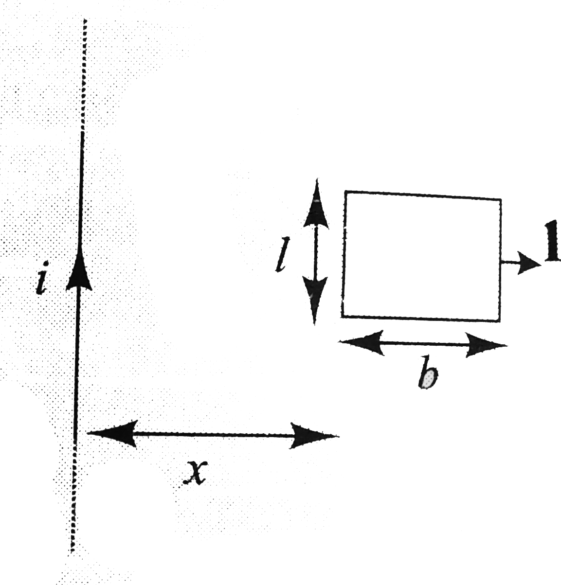
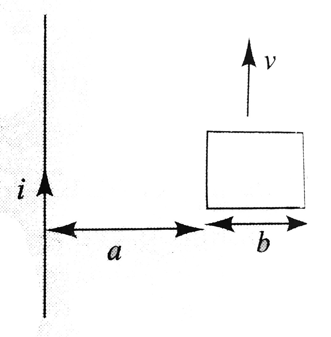
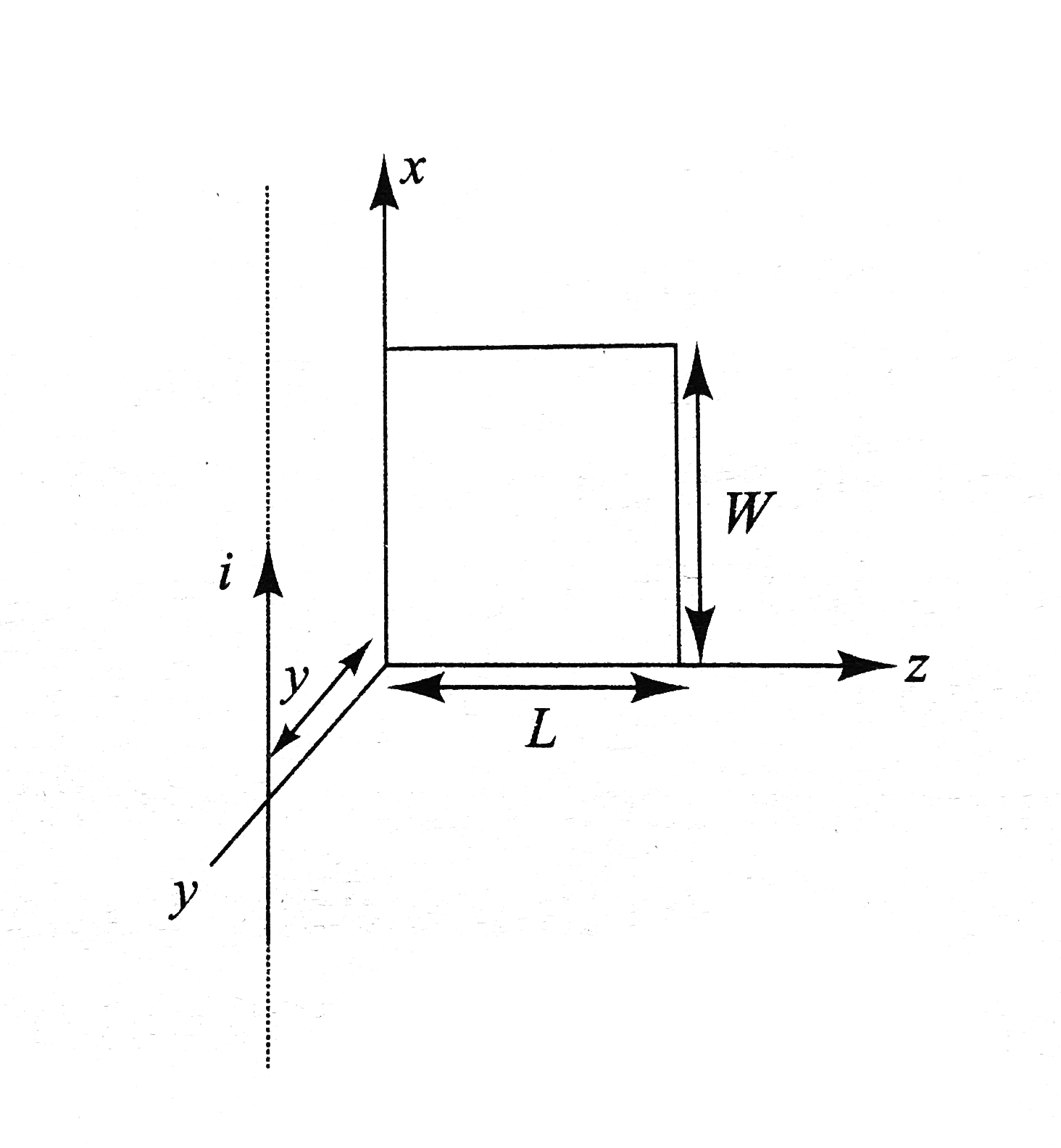
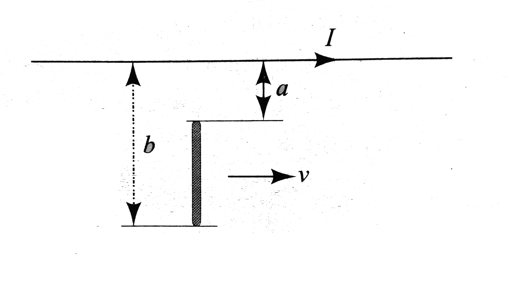
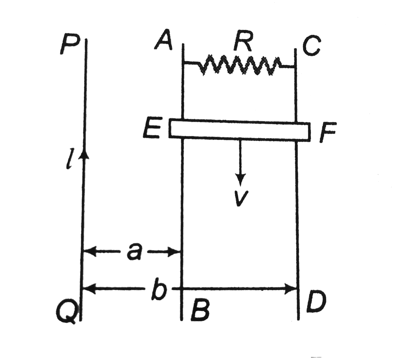
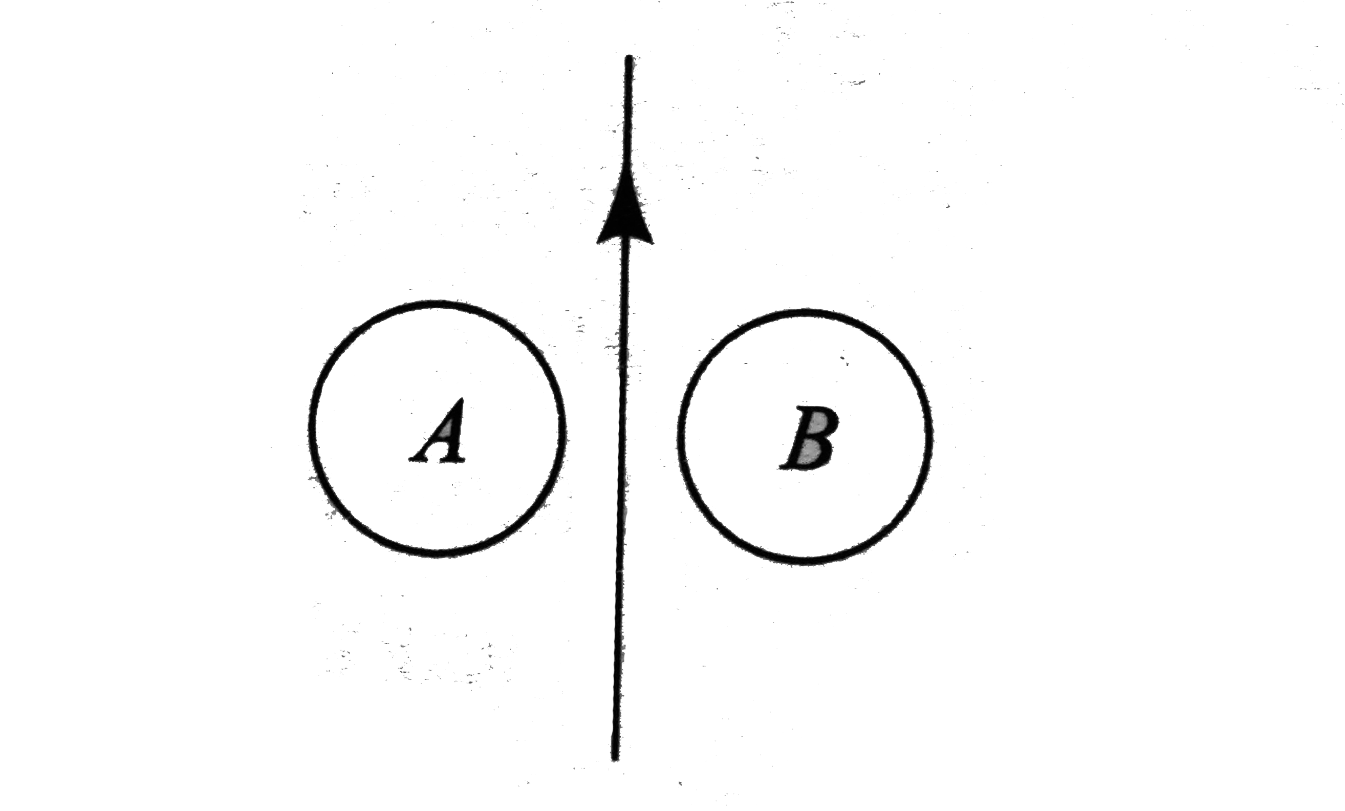
A rectangular loop of wire with dimensions shown in figure is coplanar with a long wire carrying current 'I'. The distance between the wire and the left side of the loop is r. The loop is pulled to the right as indicated. What are the directions of the induced current in the loop and the magnetic forces on the left and right sides of the loop when the loop is pulled ?
 View Solution
Question 98
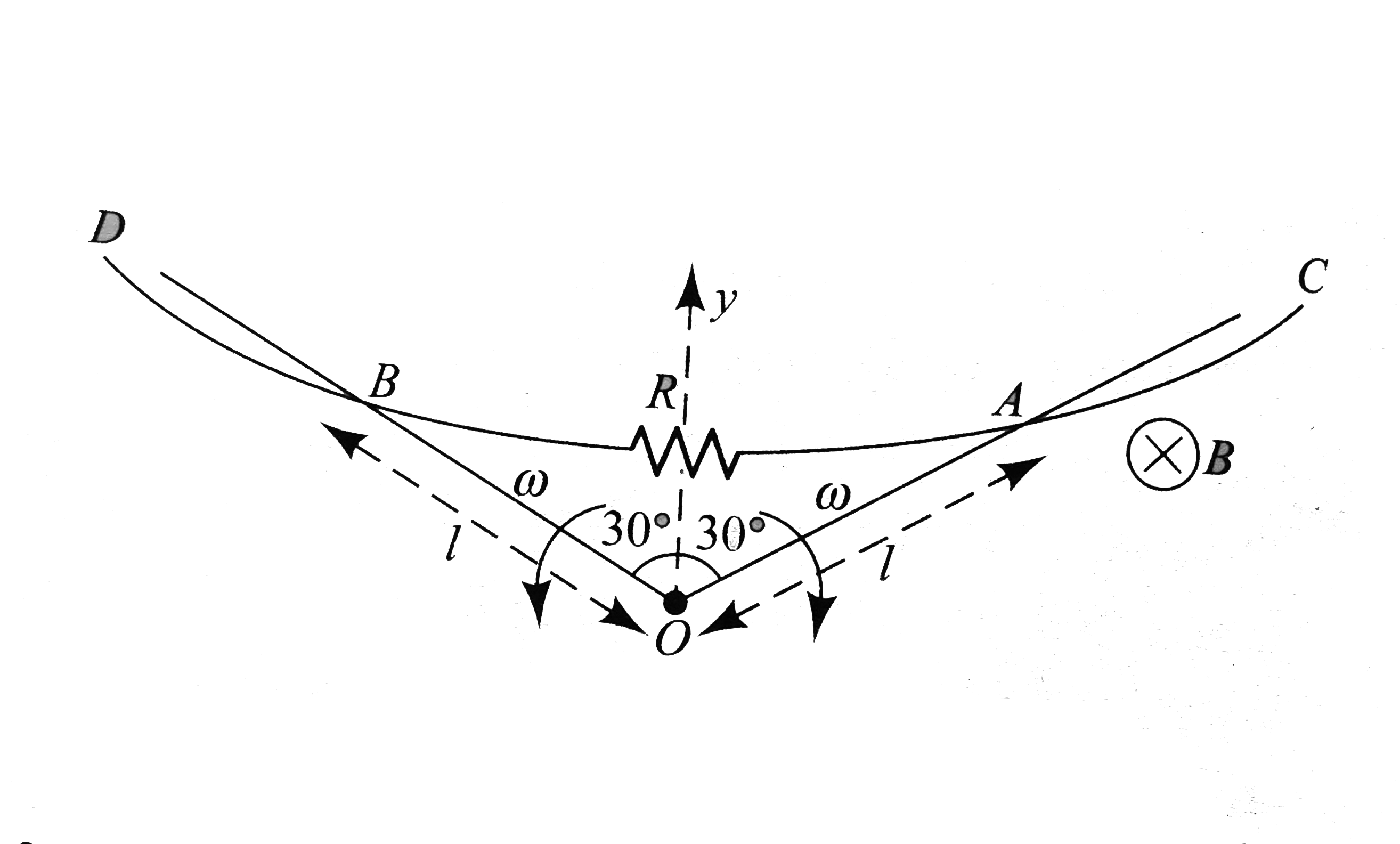
In fig. there exists a uniform magnetic field B into the plane of paper. Wire CD is in the shape of an arc and is fixed. OA and OB are the wires rotating with angular velocity ω as shown in the figure in the same plane as that of the arc about point O. If at some instant, OA=OB=l and each wire makes angle θ=30∘ with y-axis, then teh current through resistance R is (wires OAandOB have no resistance)
 View Solution
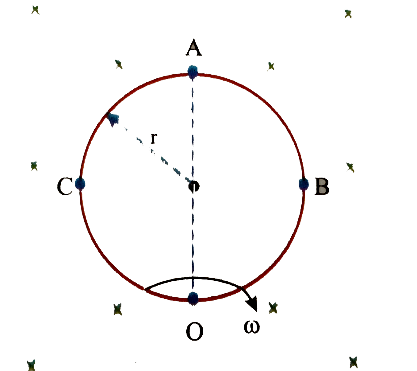
Question 99
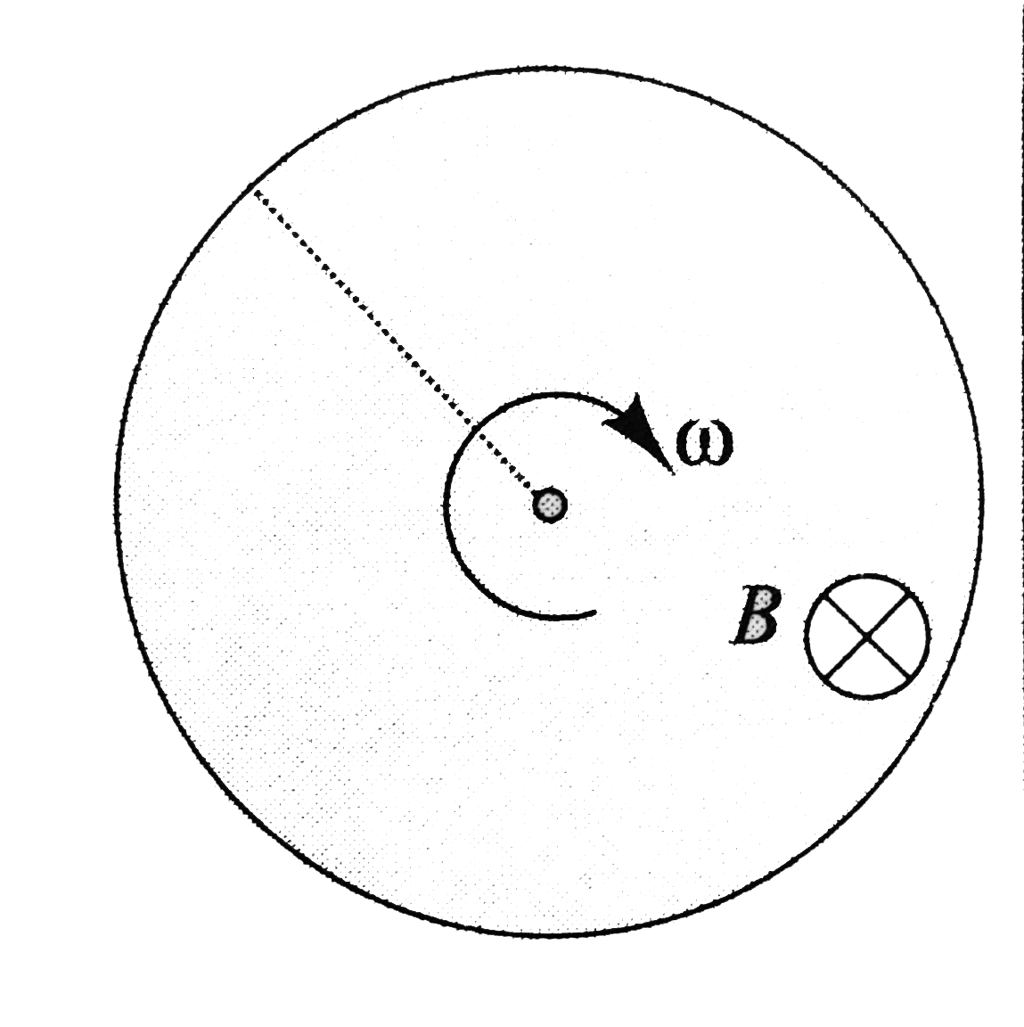
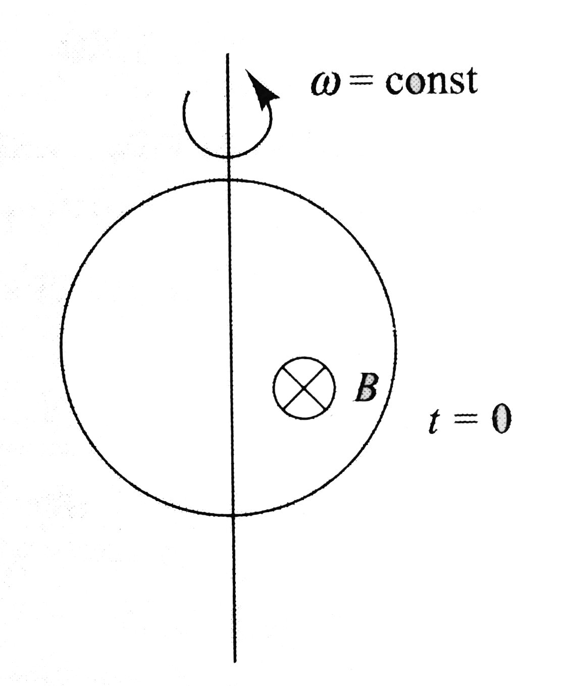
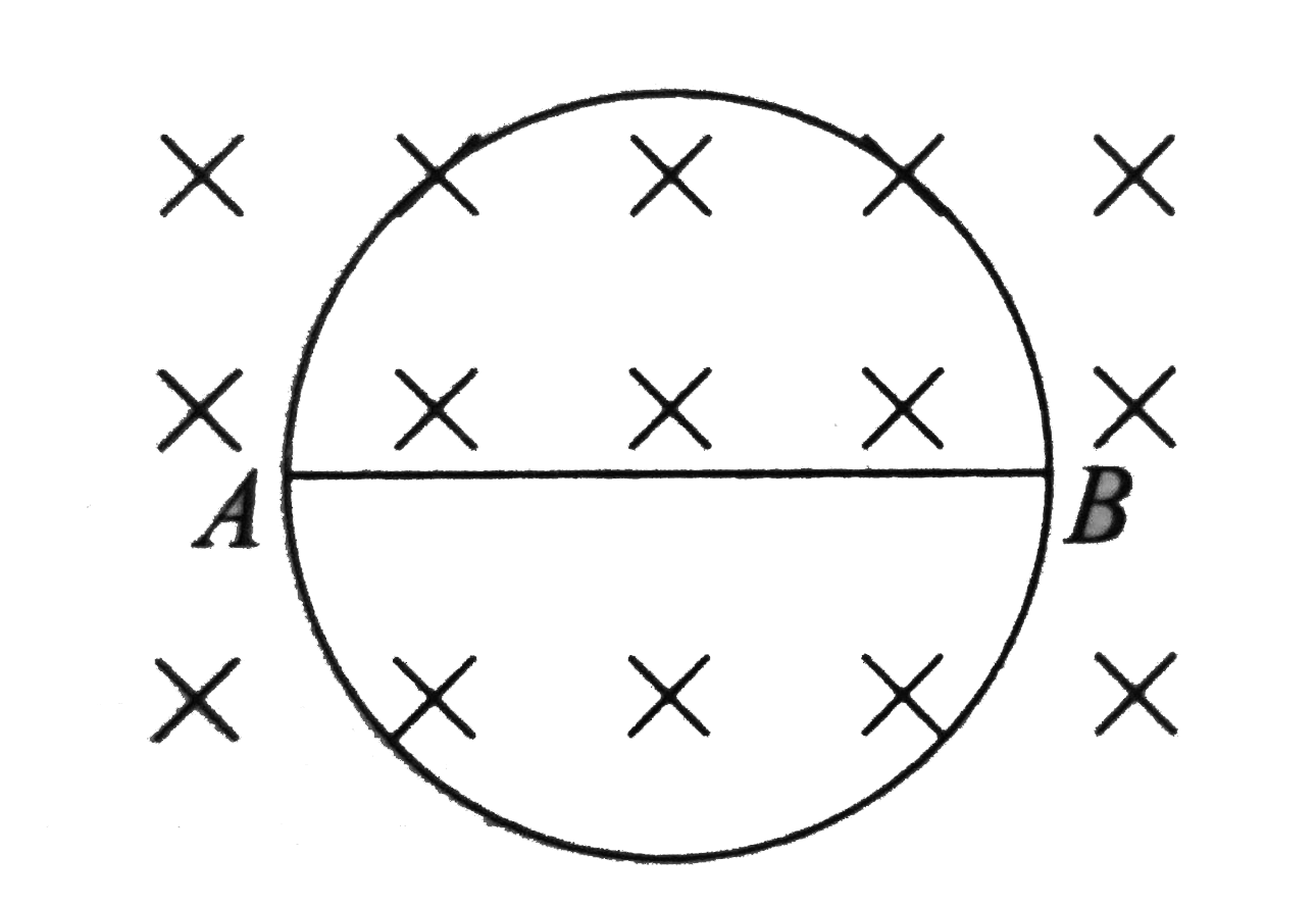
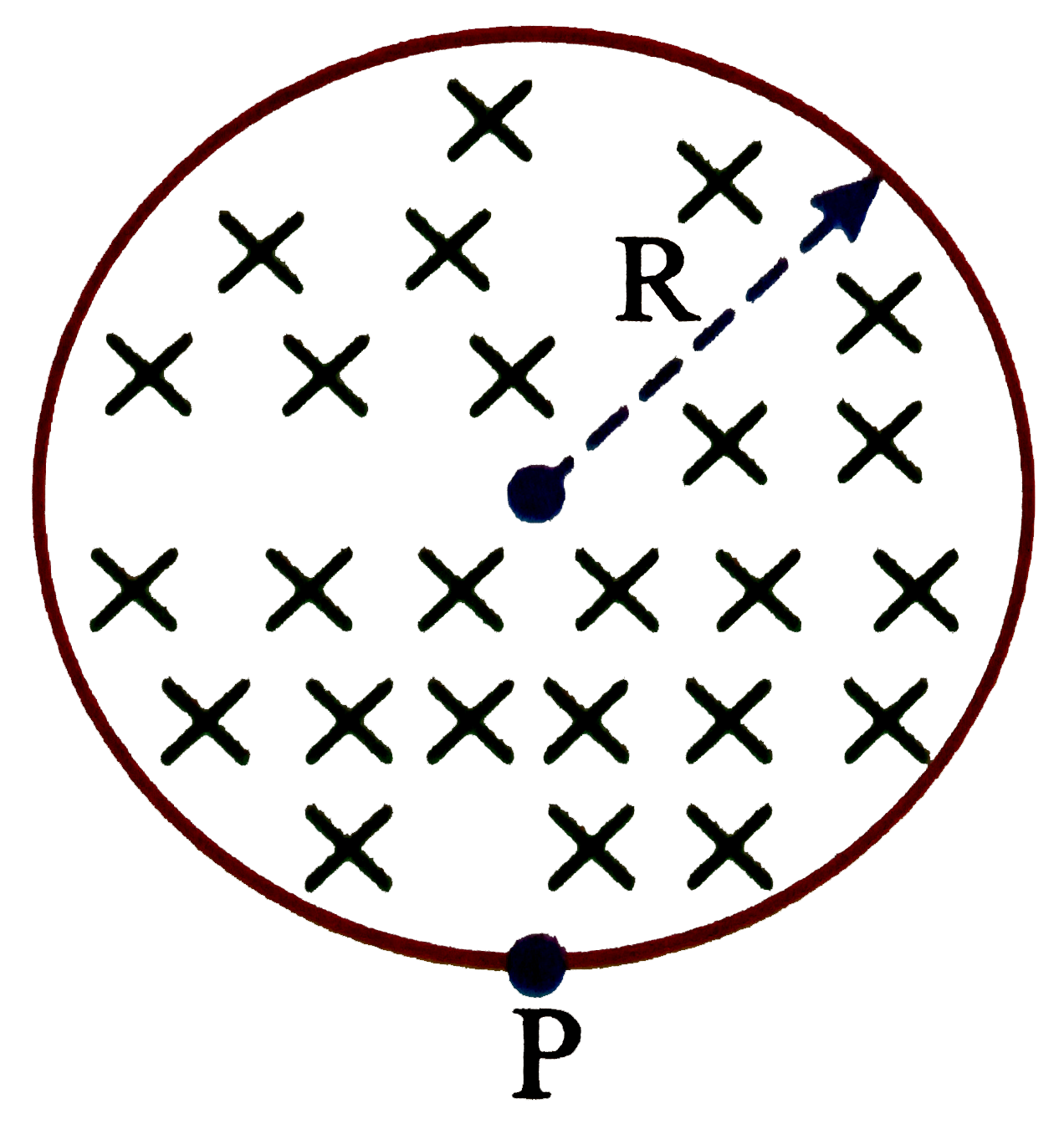
In figure, there is conducting ring having resistance R placed in the plane of paper in a uniform magnetic field B0. If the rings is rotating in the plane of paper about an axis passing through point O and perpendicular to the plane of paper with constant angular speed ω in clockwise direction, then
 View Solution
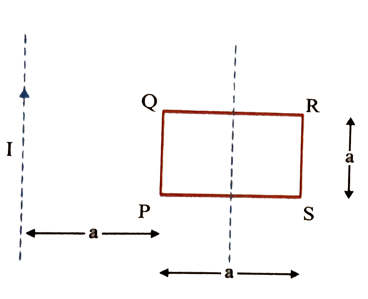
Question 103
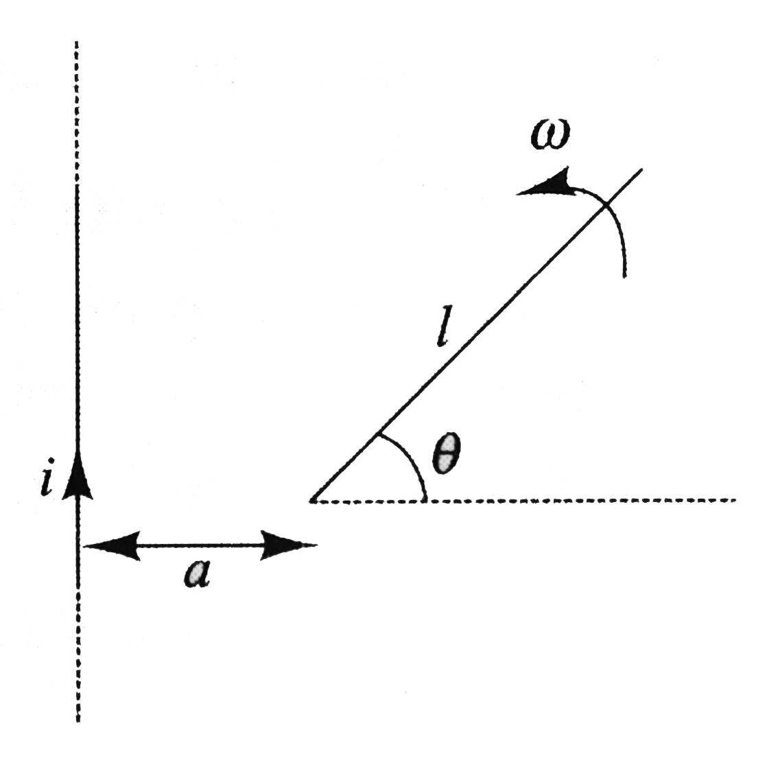
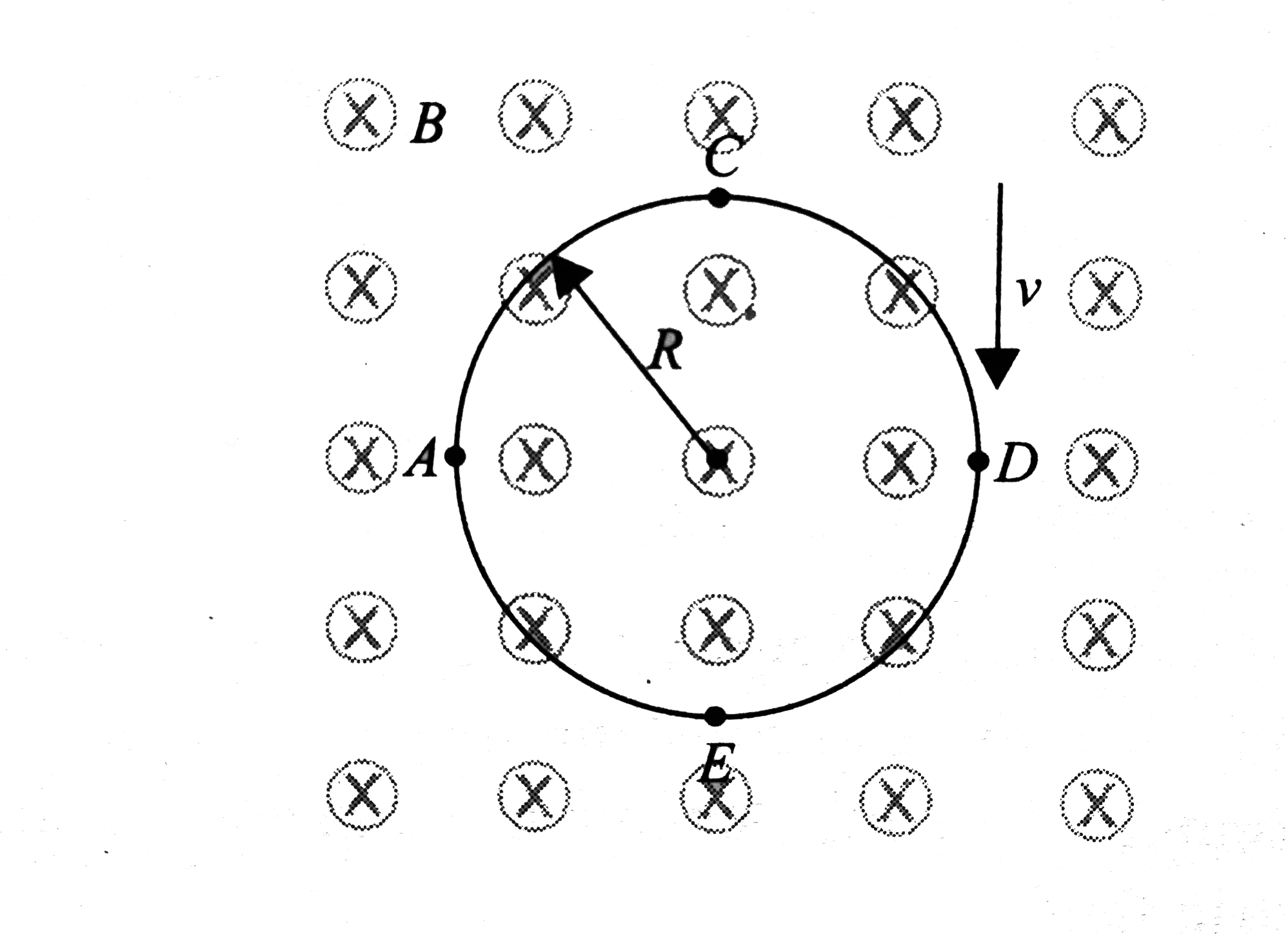
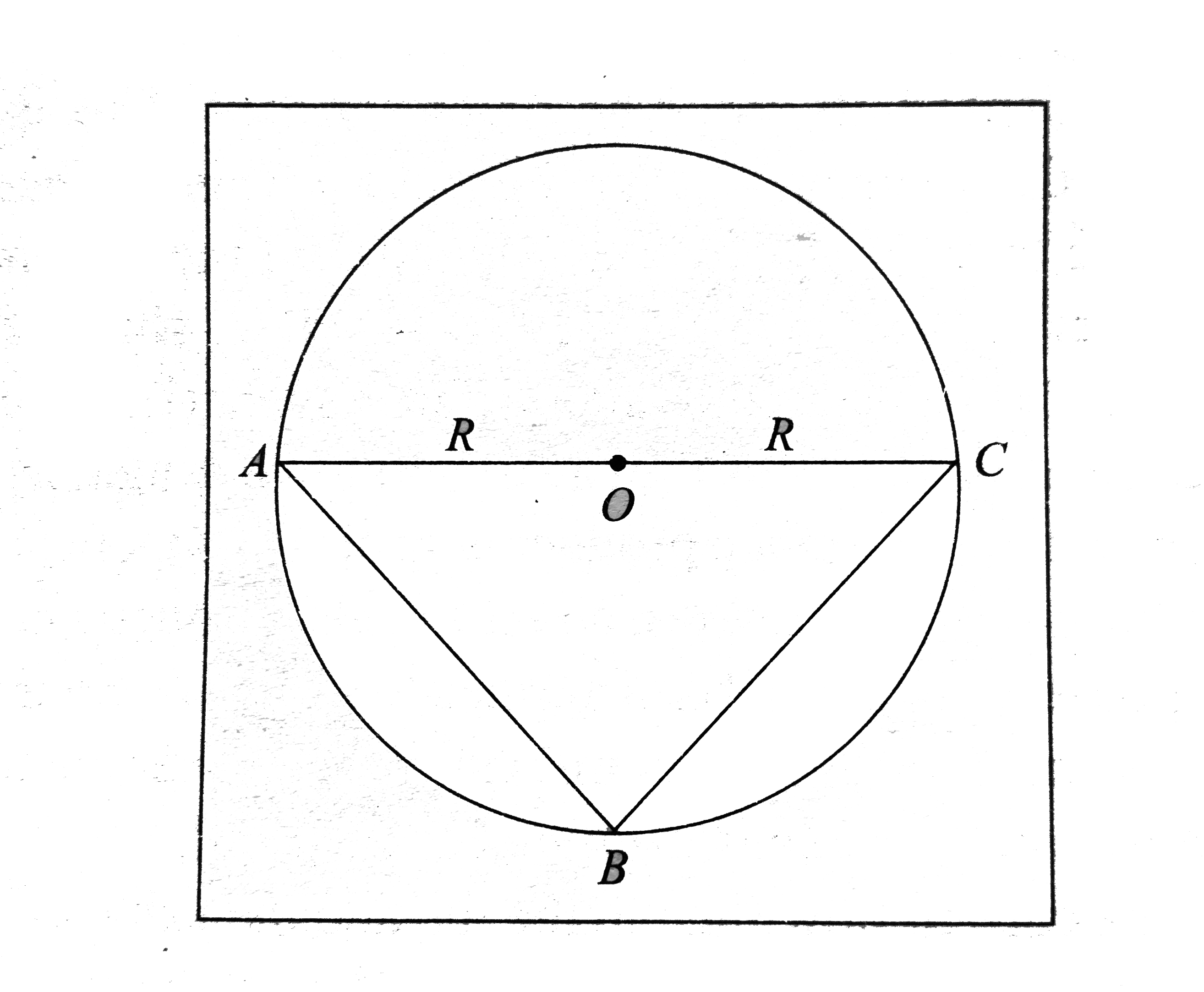
A square loop PQRS of side 'a' and resistance 'r' is placed near an infinitely long wire carrying a constant current I. The sides PQ and RS are parallel to the wire. The wire and the loop are in the same plane. The loop is rotated by 180∘ about an axis parallel to the long wire and passing through the mid points of the side QR and PS. The total amont of charge which passes through any point of the loop during rotation is:
 View Solution
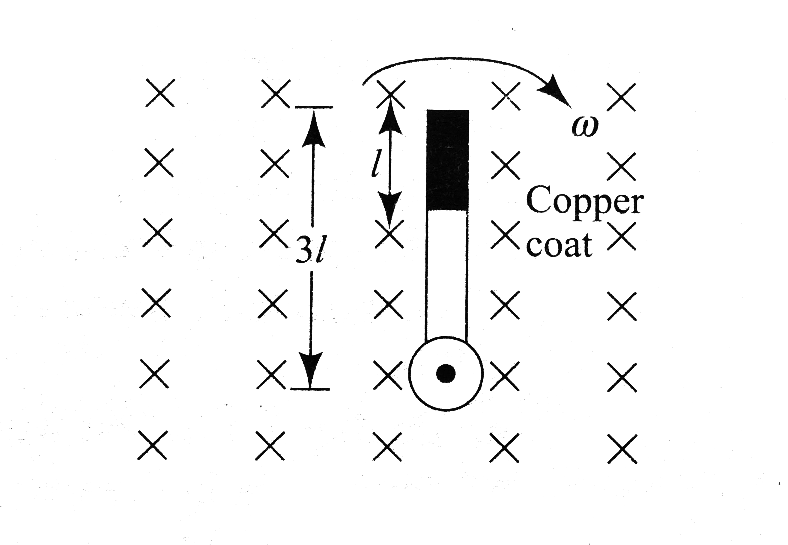
Question 104
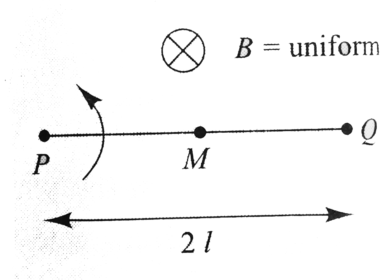
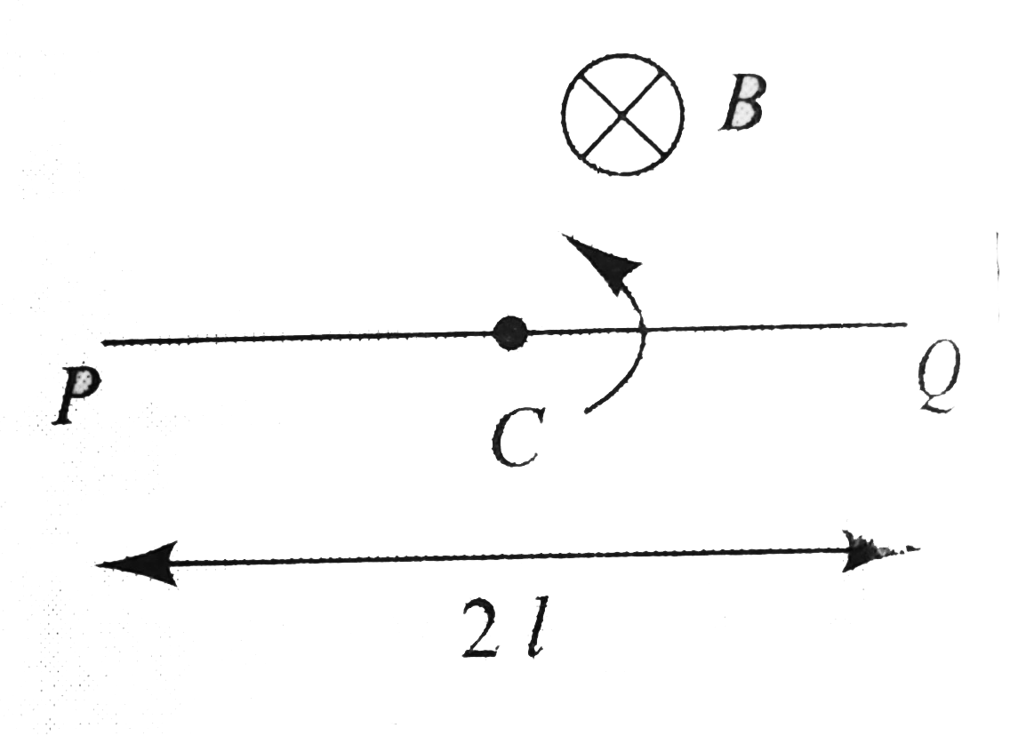
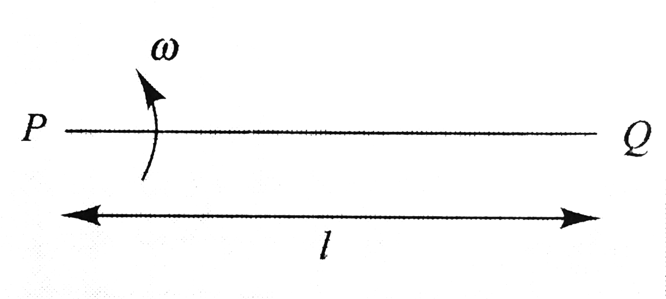
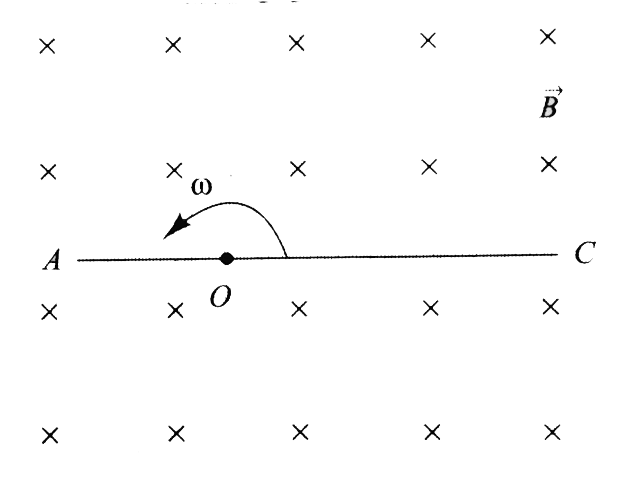
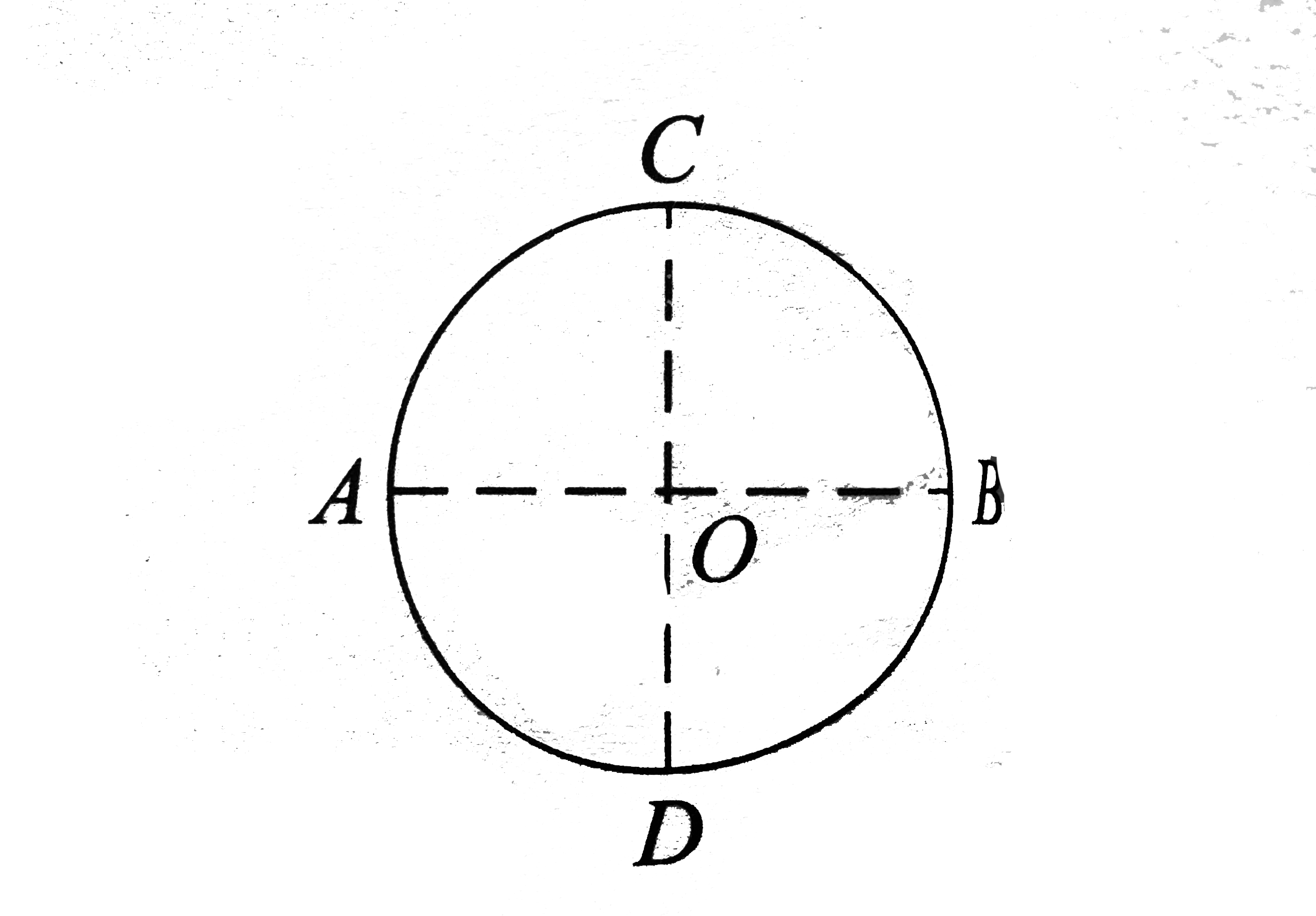
A wooden stick of length 3l is rotated about an end with constant angular velocity ω in a uniform magnetic field B perpendicular to the plane of motion. If the upper one-third of its length is coated with copper, the potential difference across the whole length of the stick is
 View Solution
Question 109
Two identical cycle wheels (geometrically have different number of spokes connected from center to rim. One if having 20 spokes and the other having only 10 (the rim and the spokes are resistance less). One resistance of value R is connected between centre and rim. The current in R will beView SolutionQuestion 114
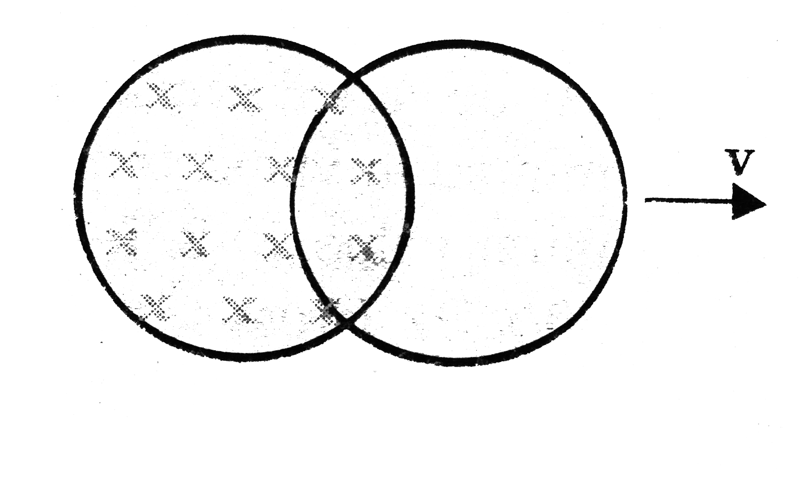
Two identical conducting rings A and B of radius R are rolling over a horizontal conducting plane with same speed v but in opposite direction. A constant magnetic field B is present pointing into the plane of paper. Then the potential difference between the highest points of the two rings is
 View Solution
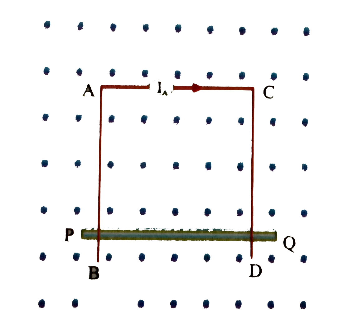
Question 118
AB and CD are fixed conducting smooth rails placed in a vertical plane and joined by a constant current source at its upper end. PQ is a conducting rod which is free to slide on the rails. A horizontal uniform magnetic field exists in space as shown in figure. If the rod PQ is released from rest then,
 View Solution
Question 119
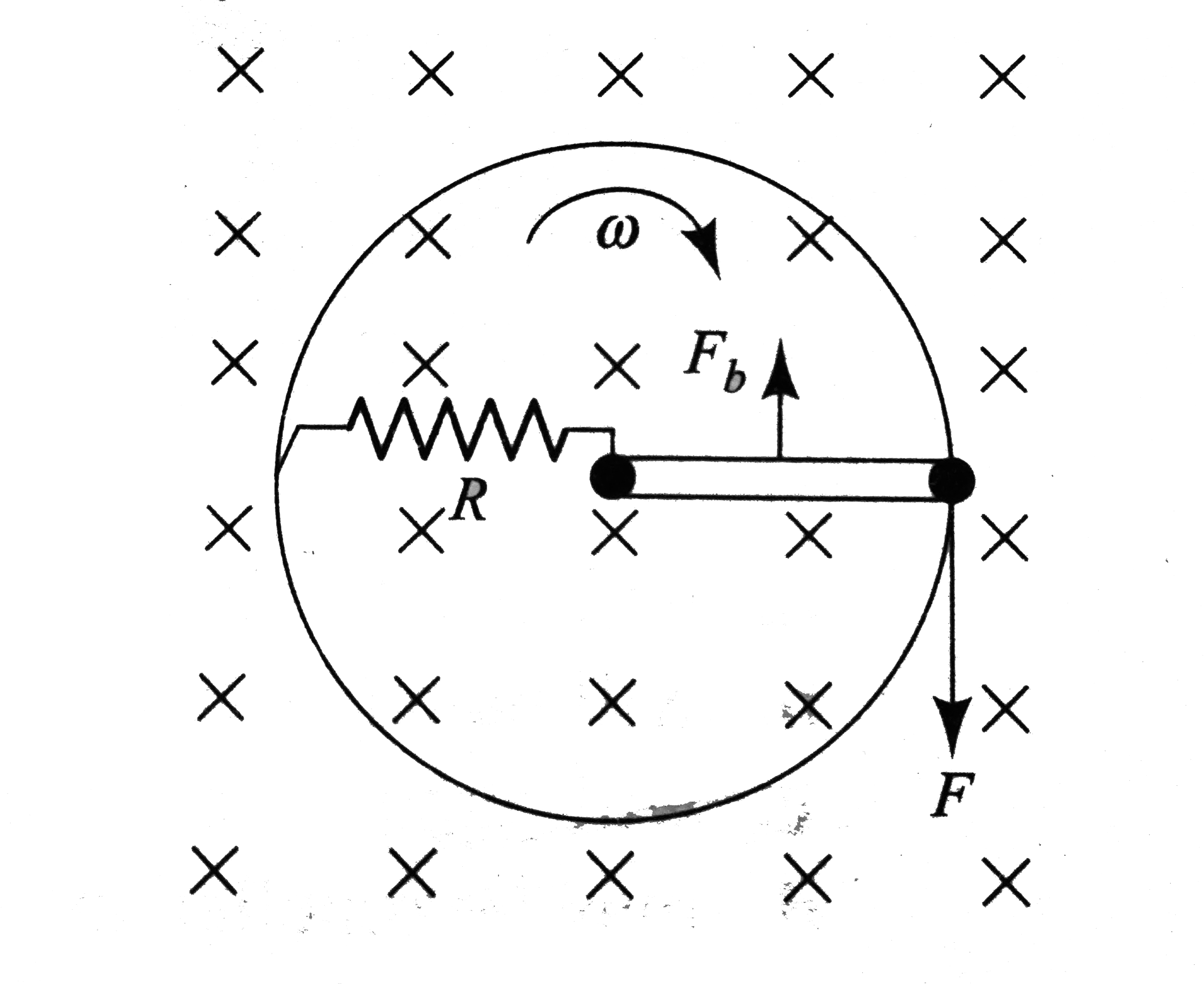
A metallic ring of radius r with a uniform metallic spoke of negligible mass and length r is rotated about its axis with angular velocity ω in a perpendicular uniform magnetic field B as shown in Fig. 3.163. The central end of the spoke is connected to the rim of the wheel through a resistor R as shown. The resistor does not rotate, its one end is always at the center of the ring and the other end is always in as shown is needed to maintain constant angular velocity of the wheel. F is equal to (the ring and the spoke has zero resistance)
 View Solution
Question 120
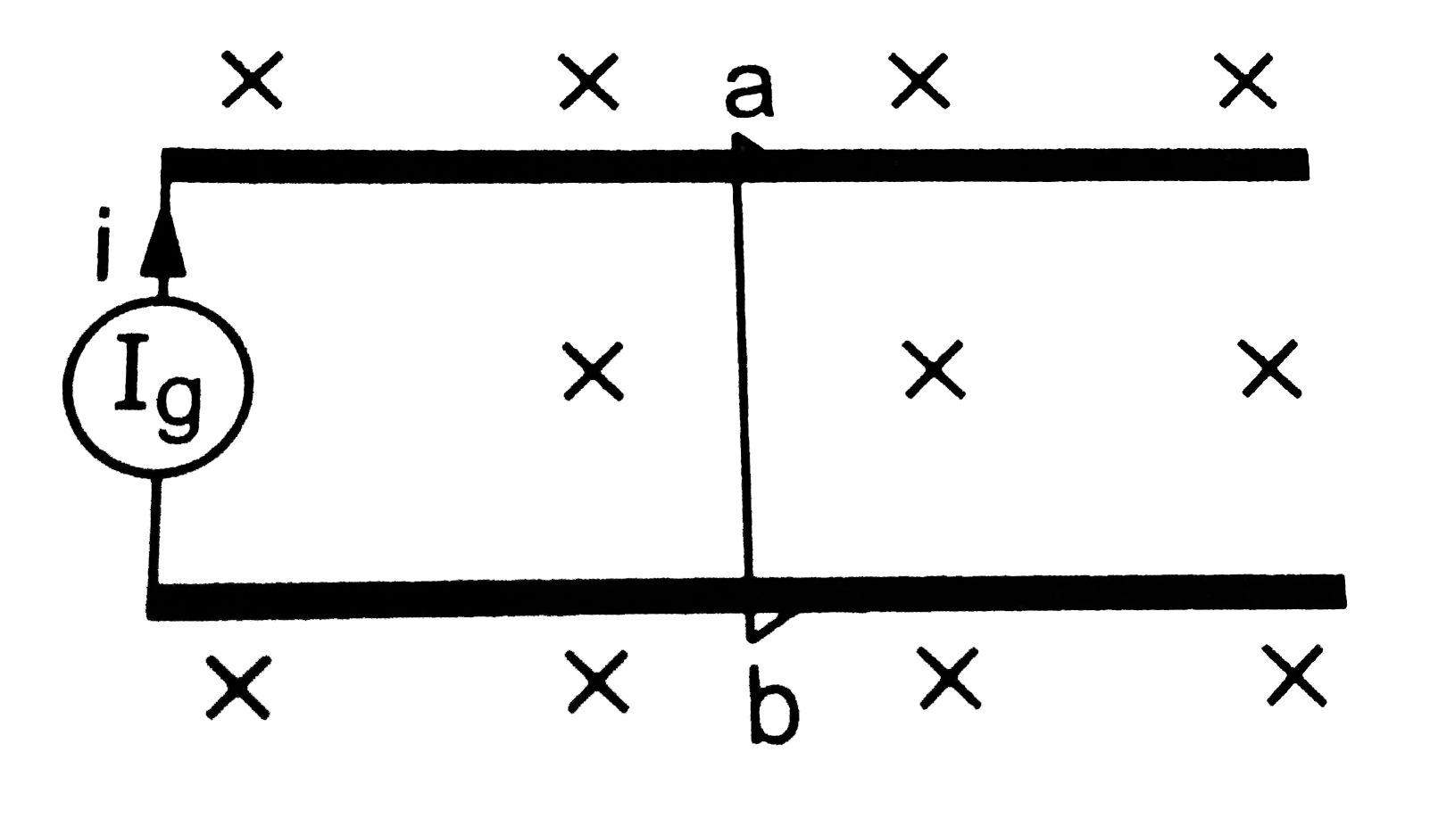
The current generator ig, shown in , sends a constant current I through the circuit. The wire ab has a length l and mass m and can slide on the smooth, horizontal rails connected to lg. The entire system lies in a vertical magnetic field B. Find velocity of the wire as a function of time.
 View Solution
Question 122
A magnetic field induction is changing in magnitude in a region at a constant rate dB/dt. A given mass m of copper drawn into a wire and formed into a loop is placed perpendicular to the field. If the values of specific resistance and density of copper are ρ and σ respectively, then the current in the loop is given by :View SolutionQuestion 125
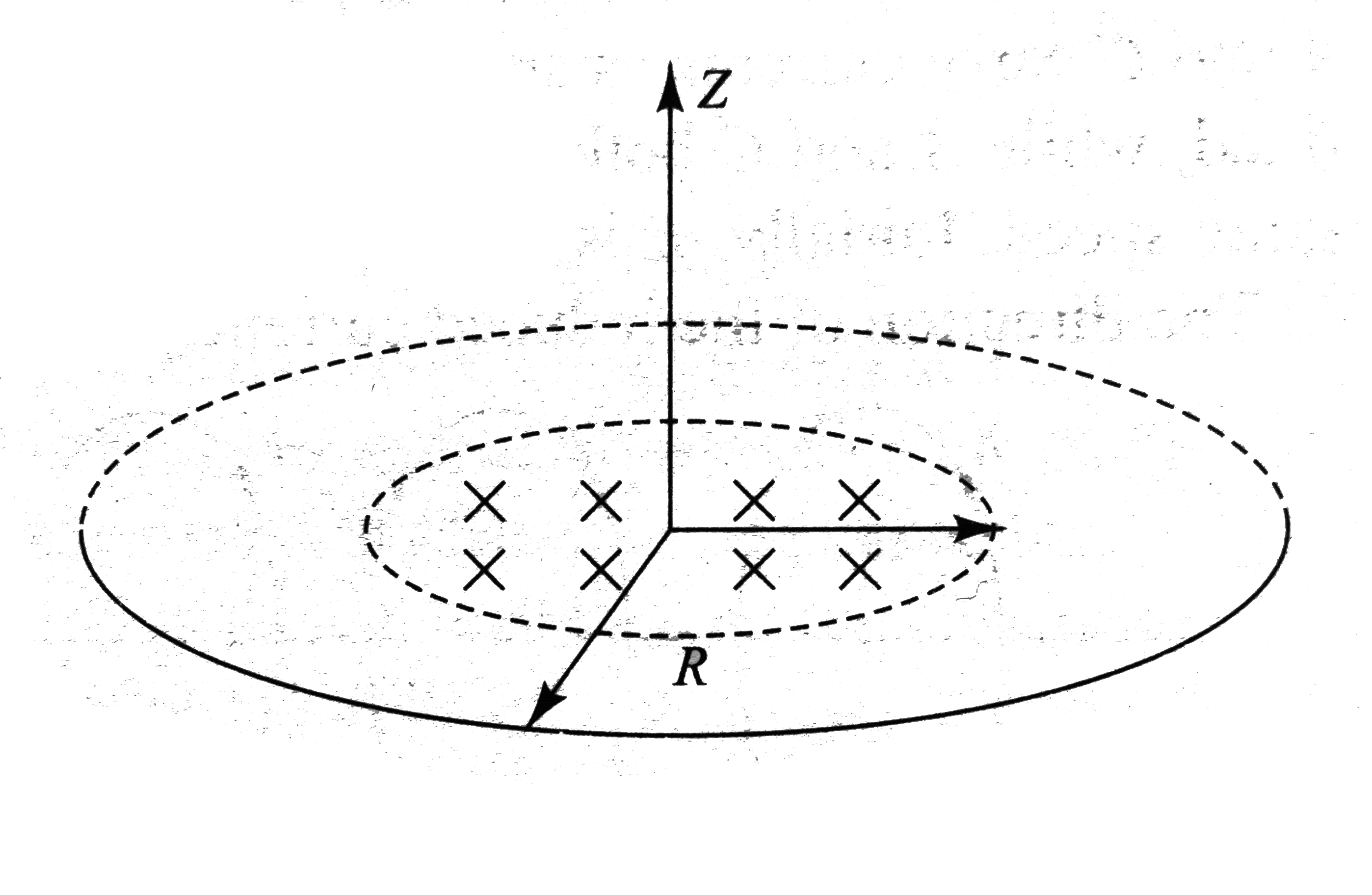
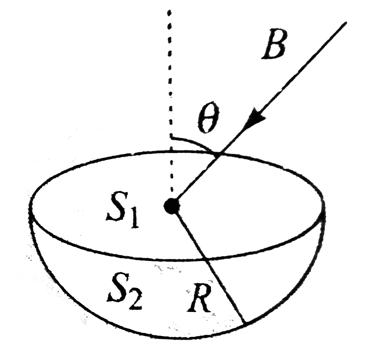
A line charge λ per unit length is pasted uniformly on to the wire of a wheel of mass m and radius R. The wheel has light non-conducting spokes and is free to rotate about a vertical axis as shown in Fig.3.166. A uniform magnetic field extends over a radial rigion of radius r given by B=−B0ˆk(r≤a,a<R)=0 (otherwise). What is the angular velocity of the wheel this field is suddenly switched off?
 View Solution
Question 126
A flexible wire loop in the shape of a circle has a radius that grows linearly with time. There is a magnetic field perpendicular to the plane of the loop that has a magnitude inversely proportional to the distance from the centre of the loop, B(r)∝1r How does the emf E vary with time?View SolutionQuestion 127
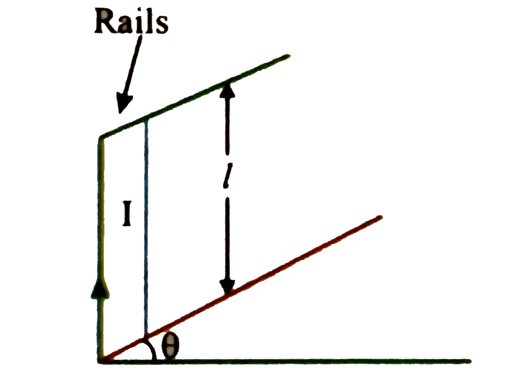
A conducting wire of length l and mass m is placed on two inclined rails as shown in figure. A current I is flowig in the wire in the direction shown When no magnetic field is present in the region, the wire is just on the verge of sliding. When a vertically upward magnetic field is switched on, the wire starts moving up the incline. The distance travelled by the wire as a function of time t will be
 View Solution
Question 128
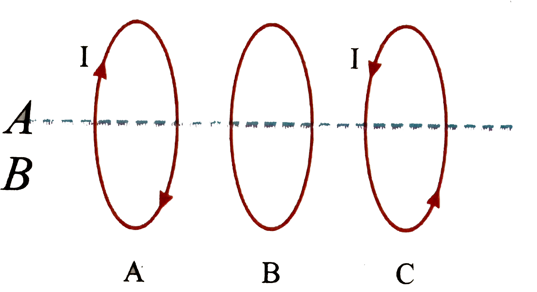
Three identical coils A,B and C carrying currents are placed co-axially with their planes parallel to one another. A and C carry current as shown in figure B is kept fixed while A and C both are moved towards B with the same speed. Initially, B is equally separated from A and C. The direction of the induced current in the coil B is
 View Solution
Question 133
A metallic wire is folded to form a square loop a side 'a'. It carries a current 'I' and is kept perpendicular to a uniform magnetic field. If the shape of the loop is changed from square to a circle without changing the length of thw wire and current, the amount of work done in doing so is View SolutionQuestion 134
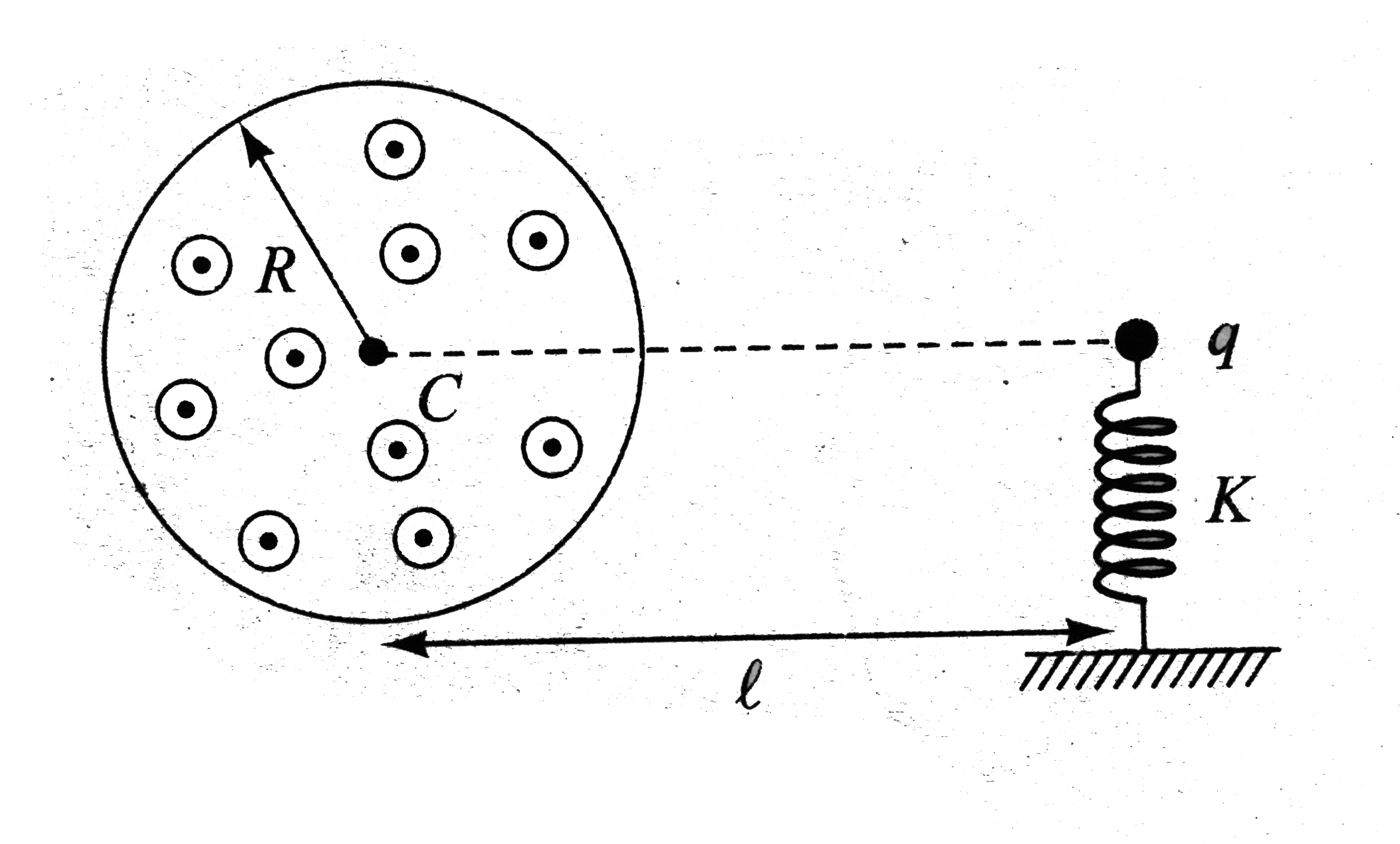
There is a horizontal cylindrical uniform but time-varying nagnetic field increasing at a constant rate dB/dt as shown in Fig. 3.173. A charged particle having charge q and mass m is kept in euilibrium, at the top of a spring of spring constant K, in such a way that it is on the horizontal line passing through the center of the magnetic field as shown in the figure. The compression in the spring will be
 View Solution
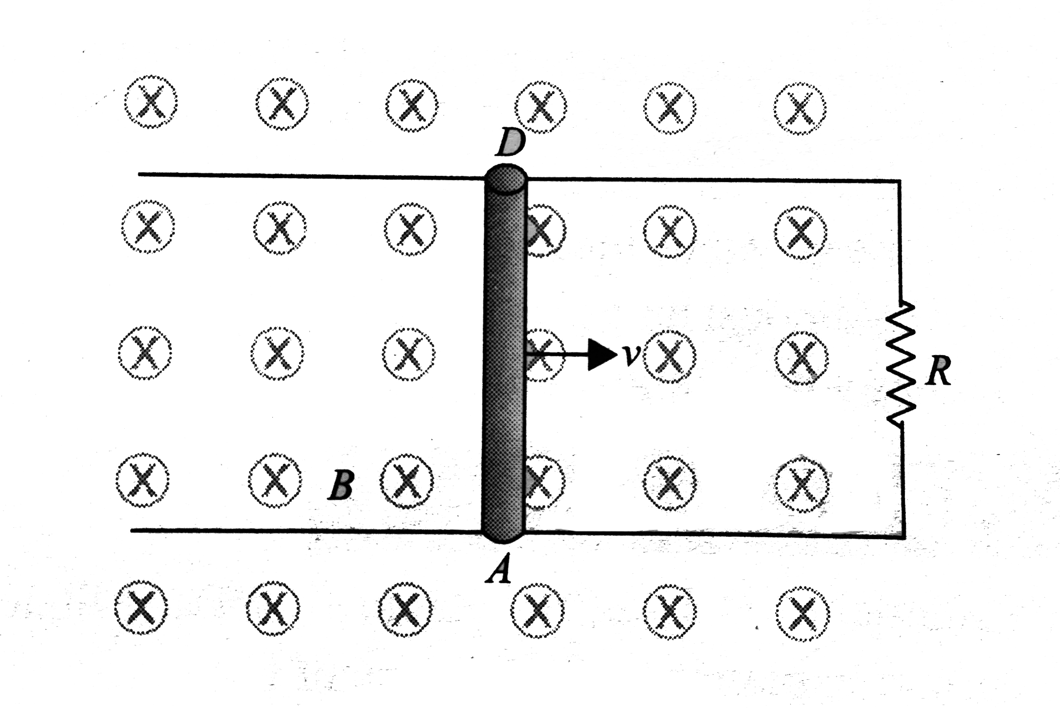
Question 140
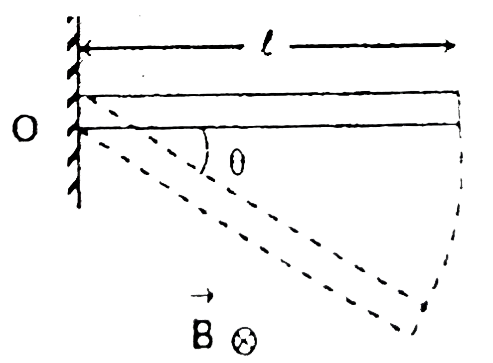
A conducting rod of length l is hinged at point O. It is free to rotate in vertical plane. There exists a uniform magnetic field →B in horizontal direction. The rod is released from position shown in the figure. Potential difference between two ends of the rod is proportional to
 View Solution
Question 141
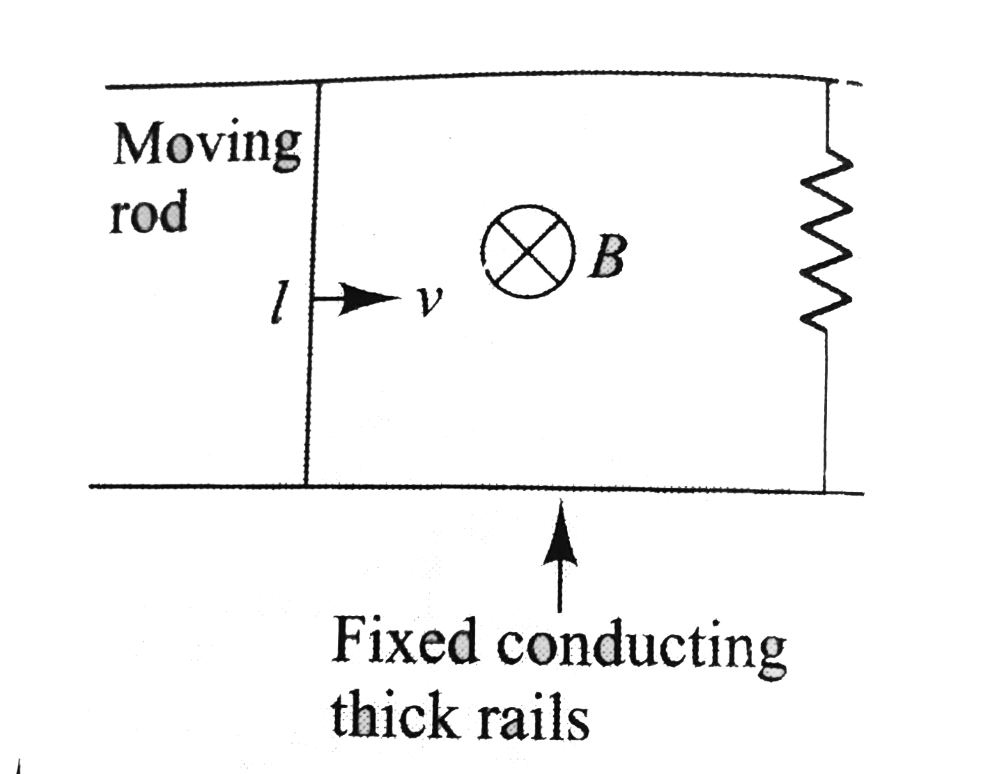
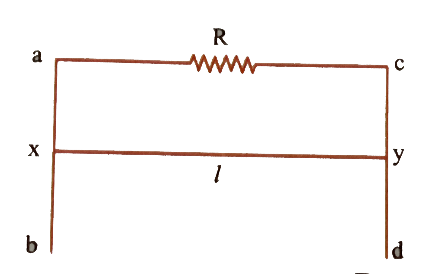
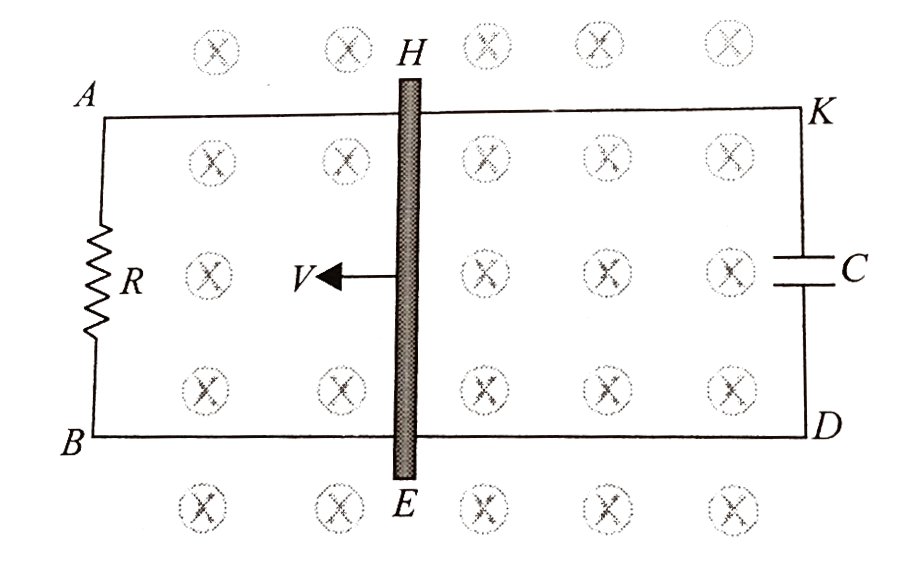
A conducting rod of length is moved at constant velocity v0 on two parallel, conducting, smooth, fixed rails, that are placed in a uniform constant magnetic field B perpendicular to the plane for the rails as shown in Fig. A resistance R is connected between the two ends of the rails.
Then which of the following is/are correct:
 View Solution
Question 142
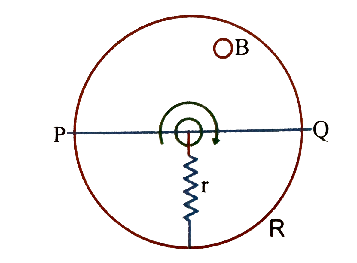
In the figure shown 'R' is a fixed conducting fixed ring of negligible resistance and radius 'a' PQ is a uniform rod of resistance r. It is hinged at the centre of the ring and rotated about this point in clockwise direction with a uniform angular velocity w. These is a uniform magnetic filled of strength 'B' ponting inwards. 'r' is a stationary resistance
 View Solution
Question 144
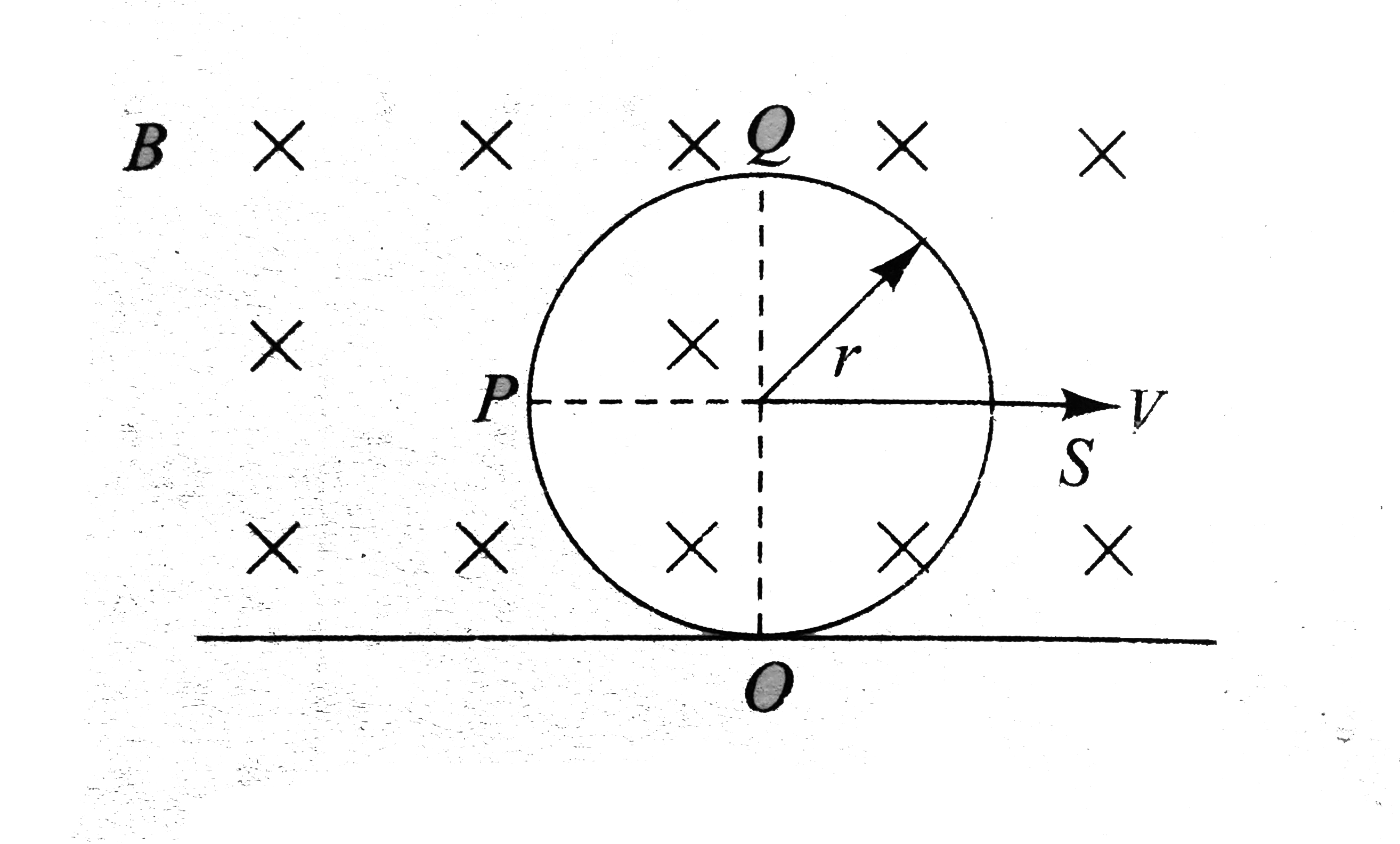
A disc of radius R is rolling without sliding on a horizontal surface with a velocity of center of mass v and angular velocity ω in a uniform magnetic field B which is perpendicular to the plane of the disc as shown in Fig. 3.179. O is the center of the disc and P,Q,R,andS are the four points on the disc. Which of the following statements is true?
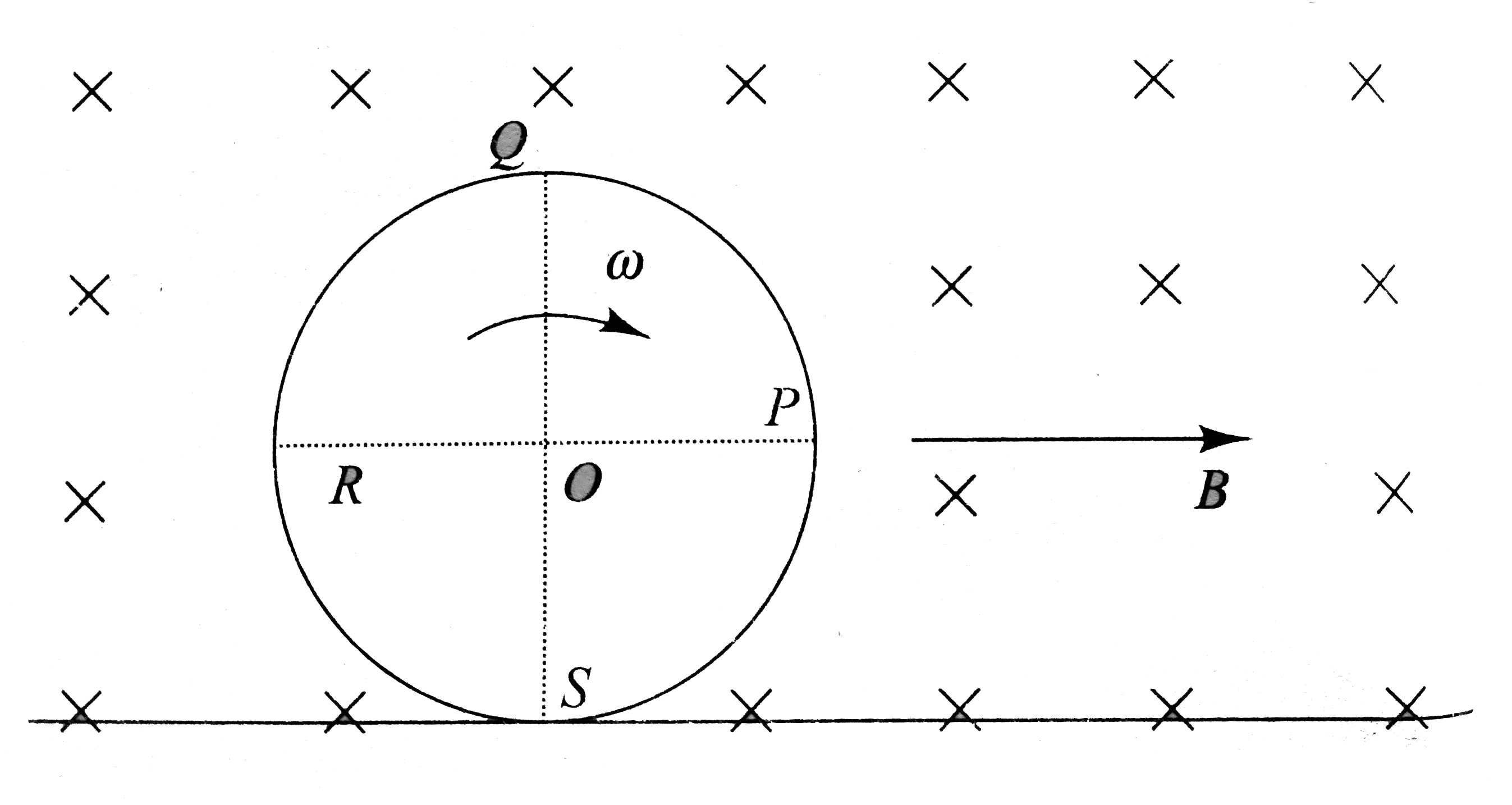 View Solution
Question 148
A highly conducting ring of radius R is perpendicular to and concentric with the axis of a long solenoid as shown in Fig. 3.182. The ring has a narrow gap of width δ in its circumference. The cross-sectional area of the solenoid is a. The solenoid has a unifoem unitial field of magnitude B(t)=B0+βt, where β>0. Assuming that no charge can flow across the gap, the face (s) accumulating an excess of positive charge is /are
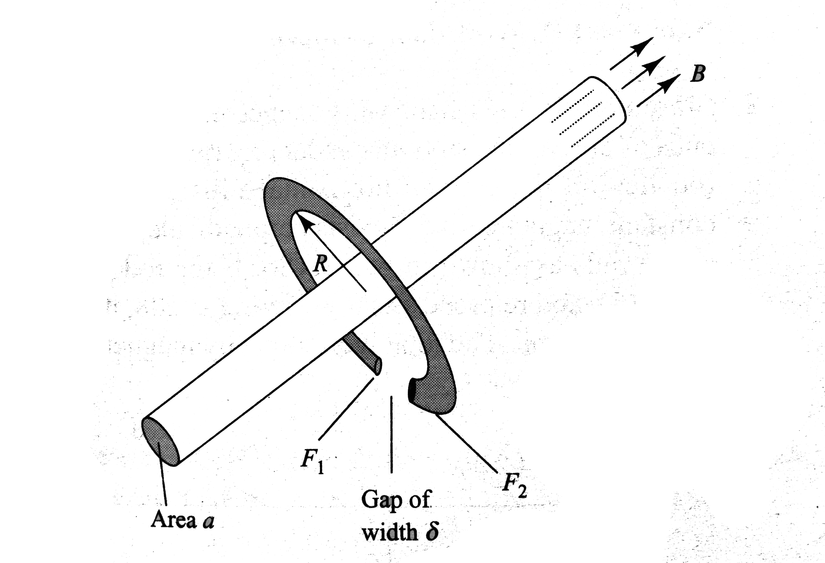 View Solution
Question 153
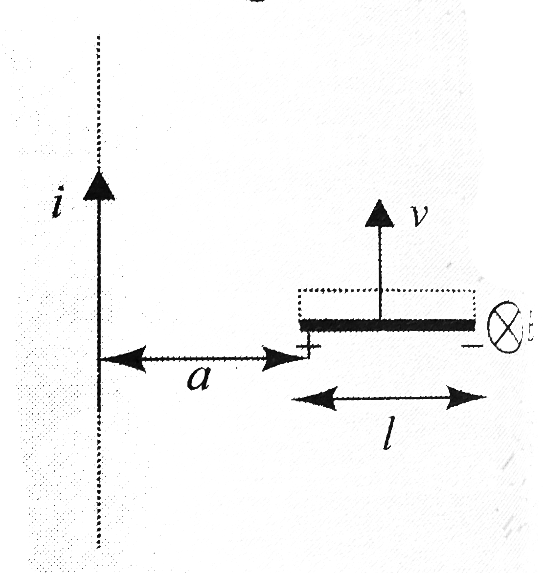
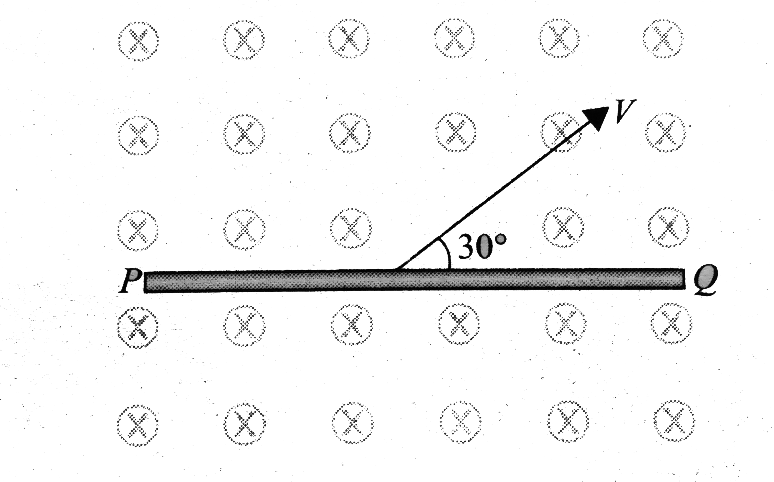
The magnitude of the earth's magnetic field at the north pole is B0 . A horizontal conductor of length l moves with a velocity v . The direction of v is perpendicular to the conductor. The induced emf is
(i) zero, if v is vertical
(ii) B0lv , if v is vertical
(iii) zero, if v is horizontal
(iv) B0lv , if v is horizontal View SolutionQuestion 155
A flat coil, C, of n turns, area A and resistance R, is placed in a uniform magnetic field of magnitude B. The plane of the coil is initially perpendicular to B. The coil,is rotated by an angle θ about a diameter and charge of amount Q flows through it. Choose the correct alternatives.View SolutionQuestion 160
Statement I: no electric current will be present within a region having uniform and constant magetic field.
Statement II: Within a region of unifrom and cinstant magnetic field →B, the path integral of magnetic field ∮→B.d→l along any closed path is zero. Hence, from Ampere cirauital law ∮→B.d→l=μ0I (where the given terms ahve usual meaning), no current can be present within a region having uniform and constant magnetic field .View SolutionQuestion 165
Statement I: A resistance R is connected between the two ends of the parallel smooth conducting rails. A conducting rod lies on these fixed horizontal rails and a uniform constant magnetic field B exists perpendicular to the plane of the rails as shown in Fig. if the rod is given a velocity υ and released as shown in Fig. 3.188, it will stop after some time. the total work done by magnetic field negative.
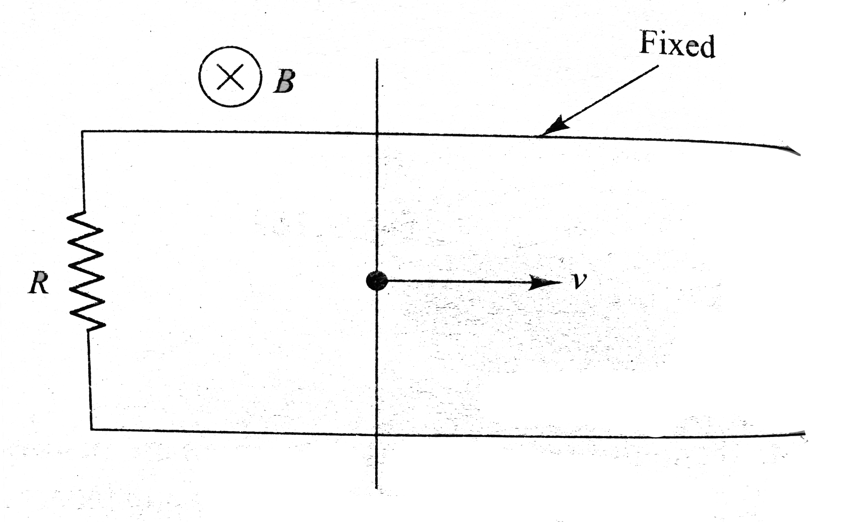
Statement II: If force acts opposite to direction of velocity its work done is negative.View SolutionQuestion 166
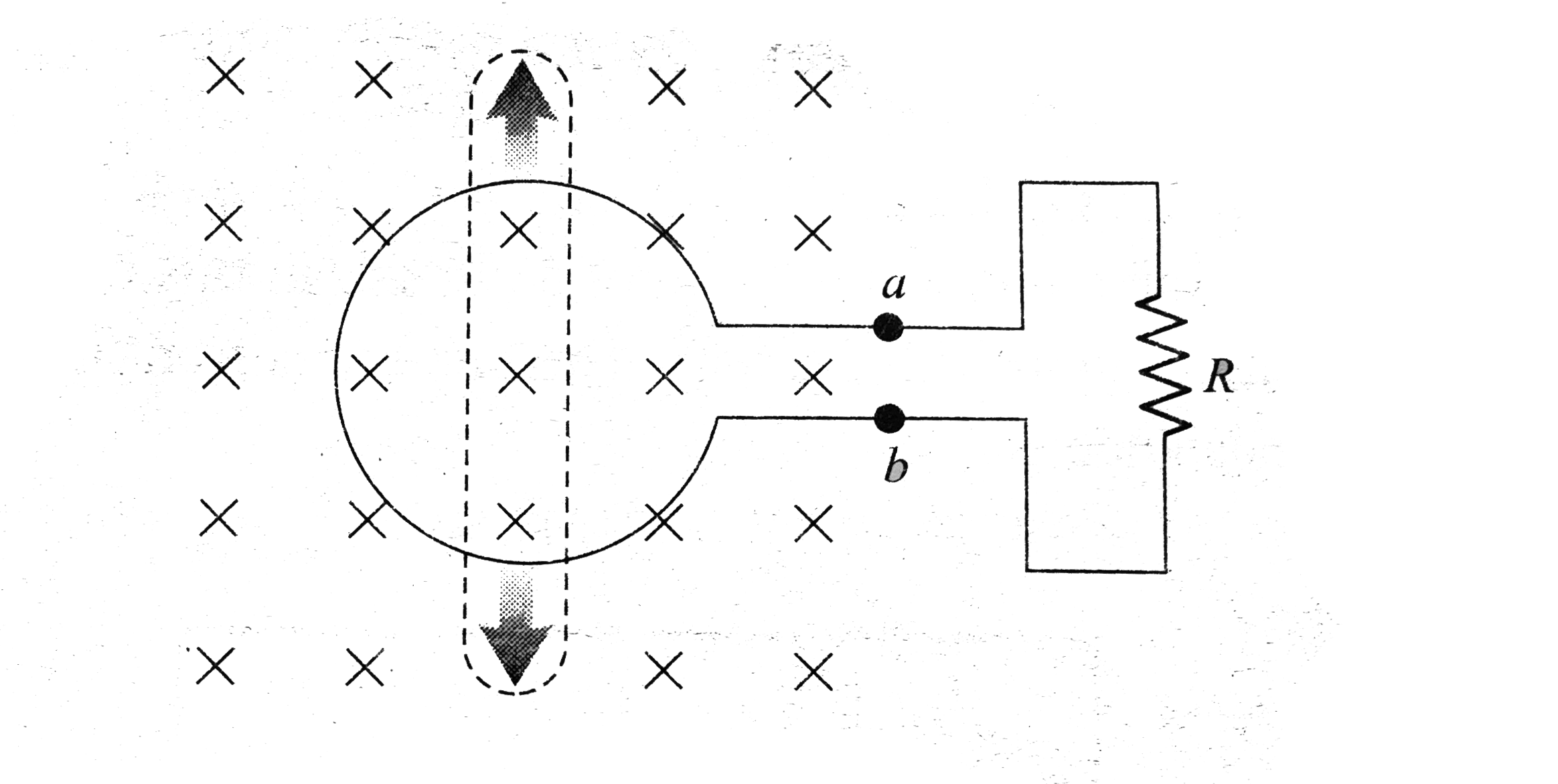
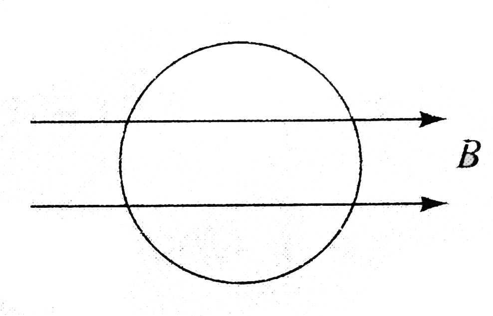
A flexible circular loop 20cm in diameter lies in a magneic field with magnitude 1.0T, direction lies into the plane of the page as shown in Fig. 3.187. The loop is pulled at the points indicated by the arrws, forming a loop of zero area in 0.314s.
The average induced emf in the circuit is View SolutionQuestion 167
A flexible circular loop 20cm in diameter lies in a magneic field with magnitude 1.0T, direction lies into the plane of the page as shown in Fig. 3.187. The loop is pulled at the points indicated by the arrws, forming a loop of zero area in 0.314s.
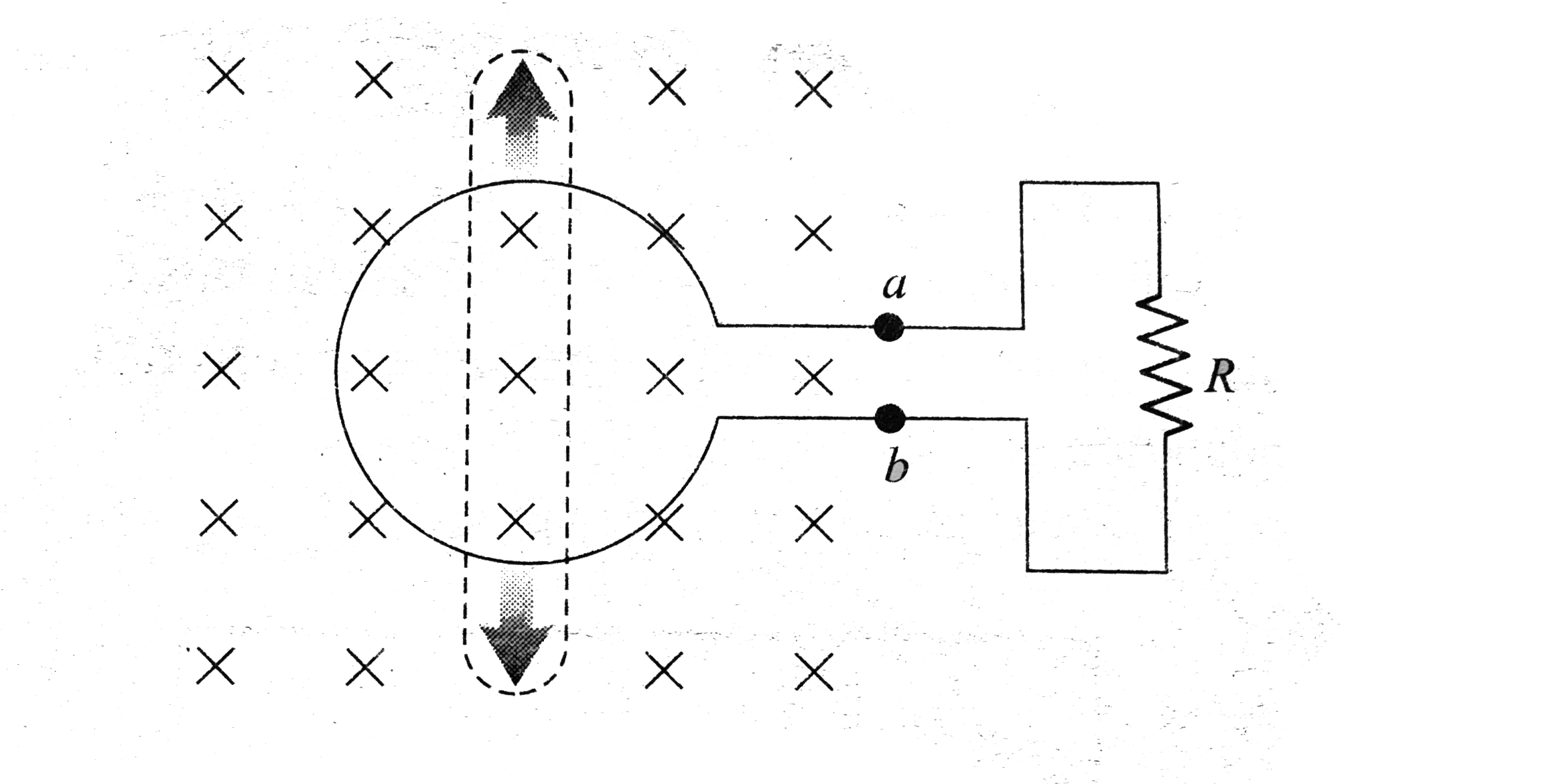
if R=0,01Ω, the magnitude and direction of current flowing in the loop areView SolutionQuestion 168
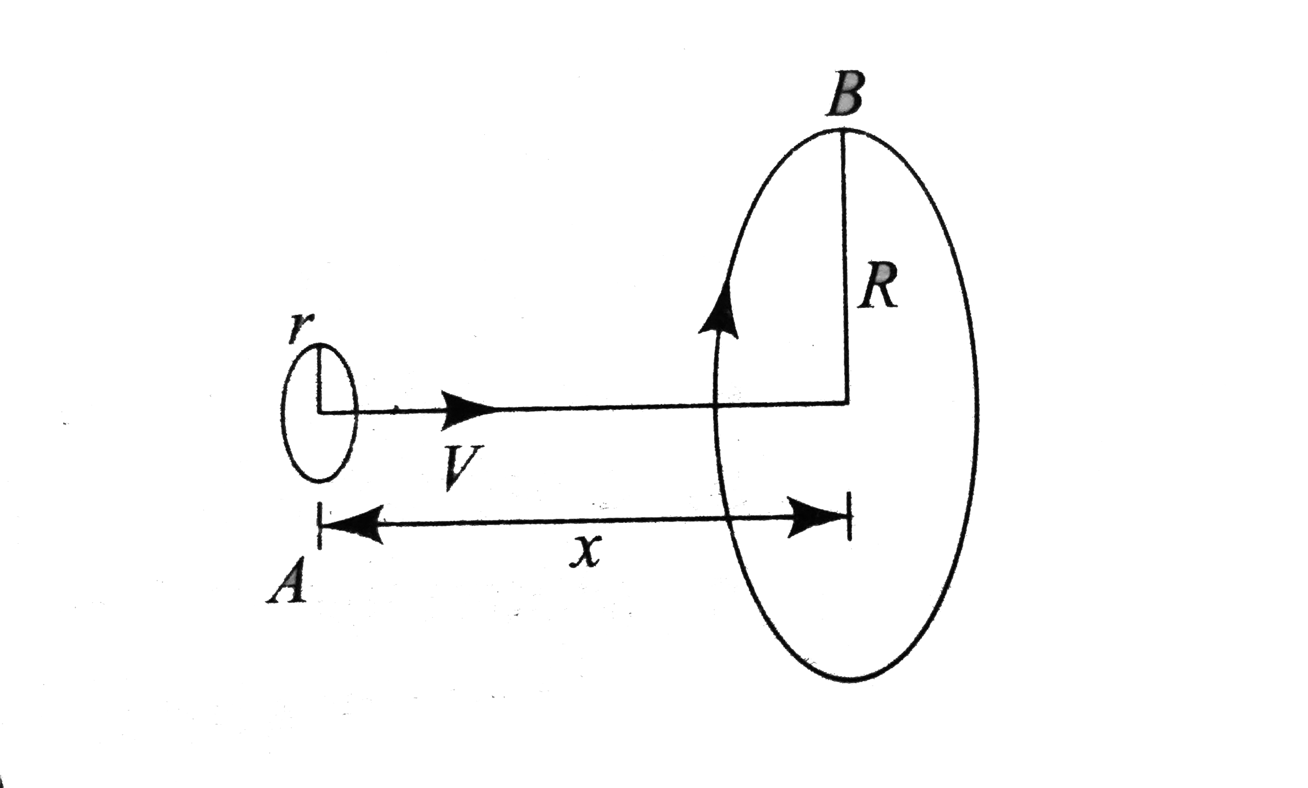
Figure. shows two parallel and coaxial loops. The smaller loop (radius r) is above the larger loop (radius R), by distance x>>R. The magnetic field due to current i in the larger loop is nearly constant throughout the smaller loop. Suppose that x is increasing at a constant rate of dx/dt=v.
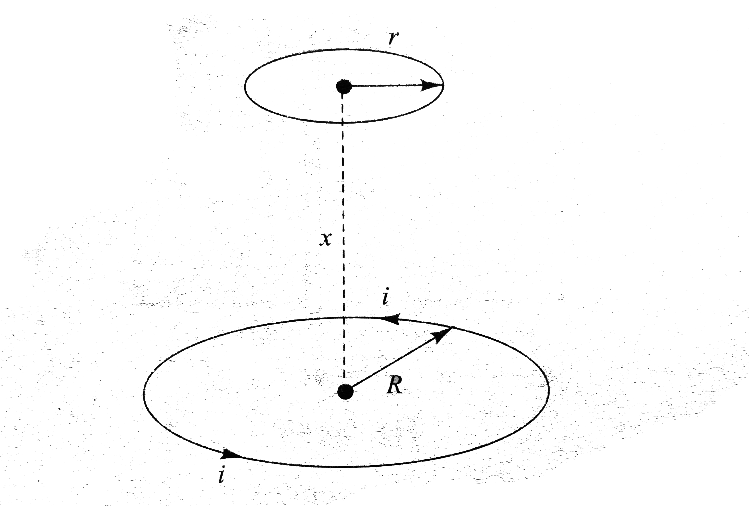
Determine the magneitc flux through the smaller loop as a function of x. View SolutionQuestion 169
Figure 3.188 shows two parallel and coaxial loops. The smaller loop (radius r) is above the larger loop (radius R), by distance x>>R. The magnetic field due to current i in the larger loop is nearly constant throughout the smaller loop. Suppose that x is increasing at a constant rate of dx/dt=v.
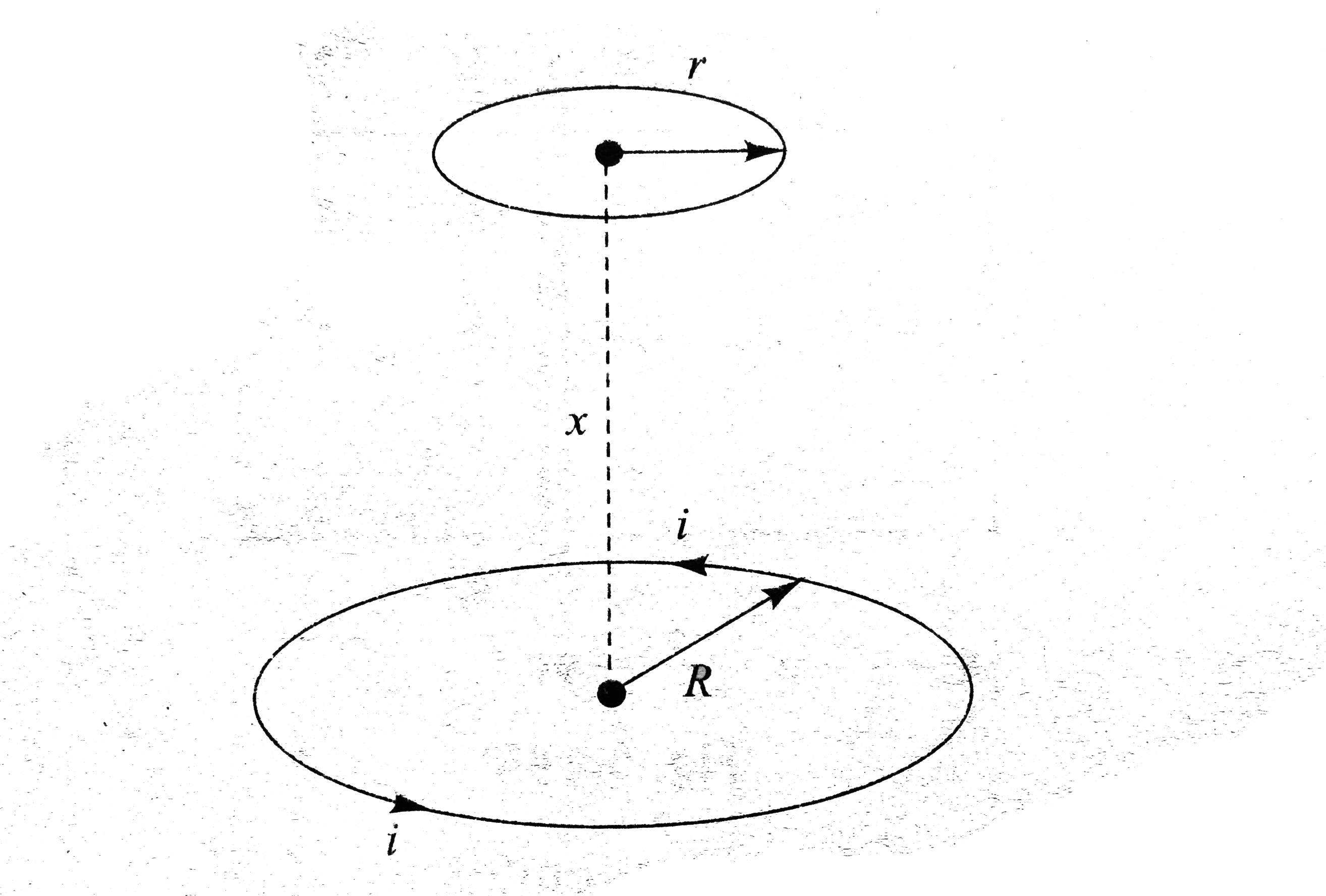
The induced emf in the smaller loop is View SolutionQuestion 170
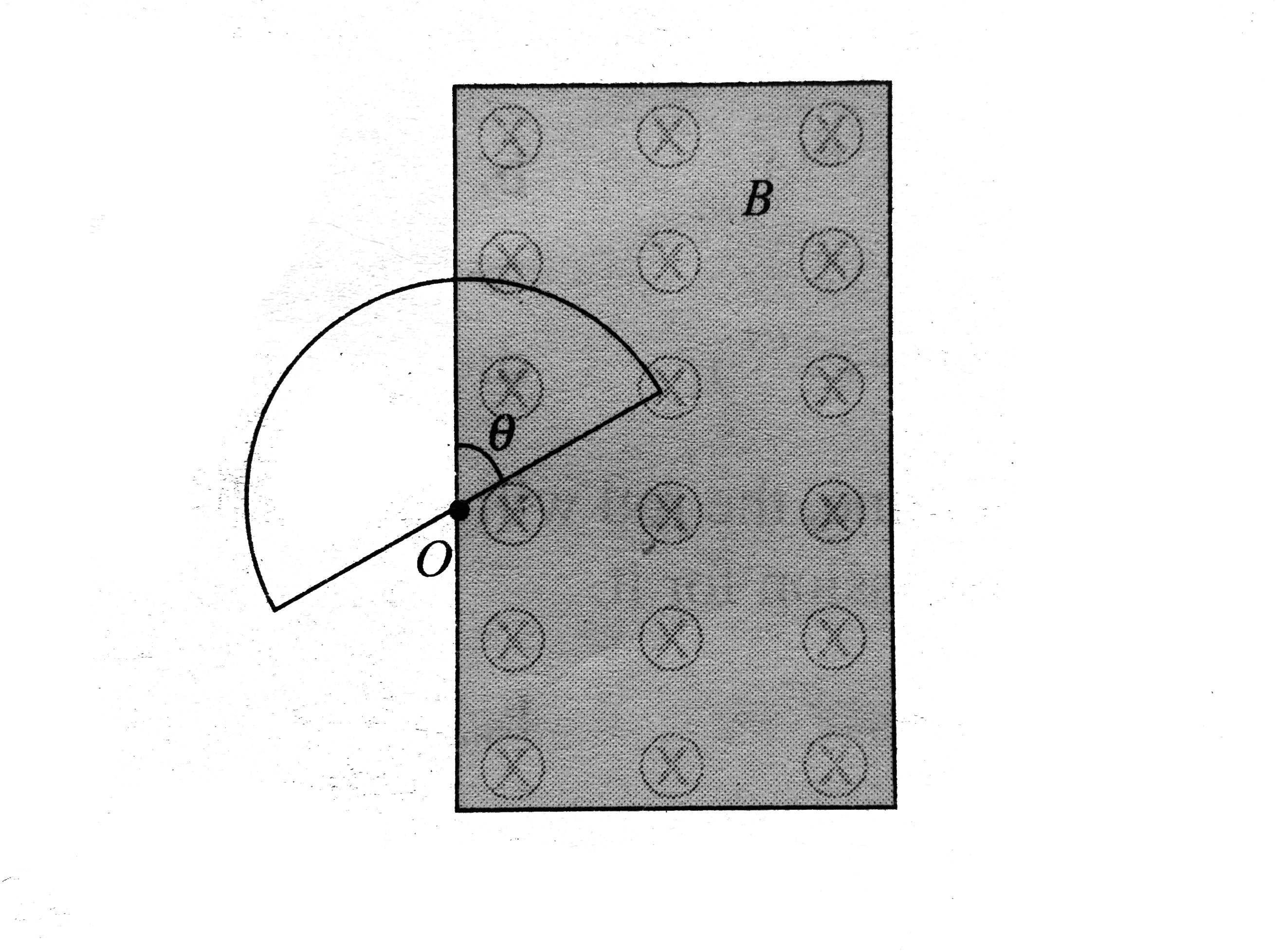
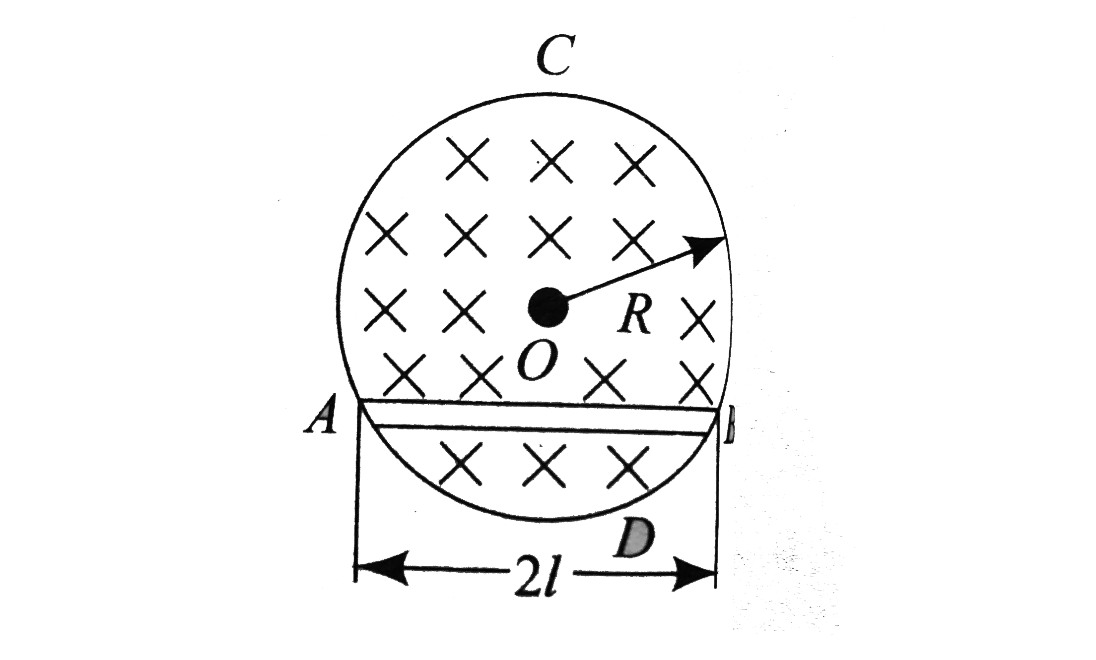
A wire loop enclosing a semicircle of radius R islocated on the boundary of a uniform magnetic field B. At the moment t=0, the loop is set into rotation with constant angular acceleration α about an axis O. The clockwise emf direction is taken to be positive.
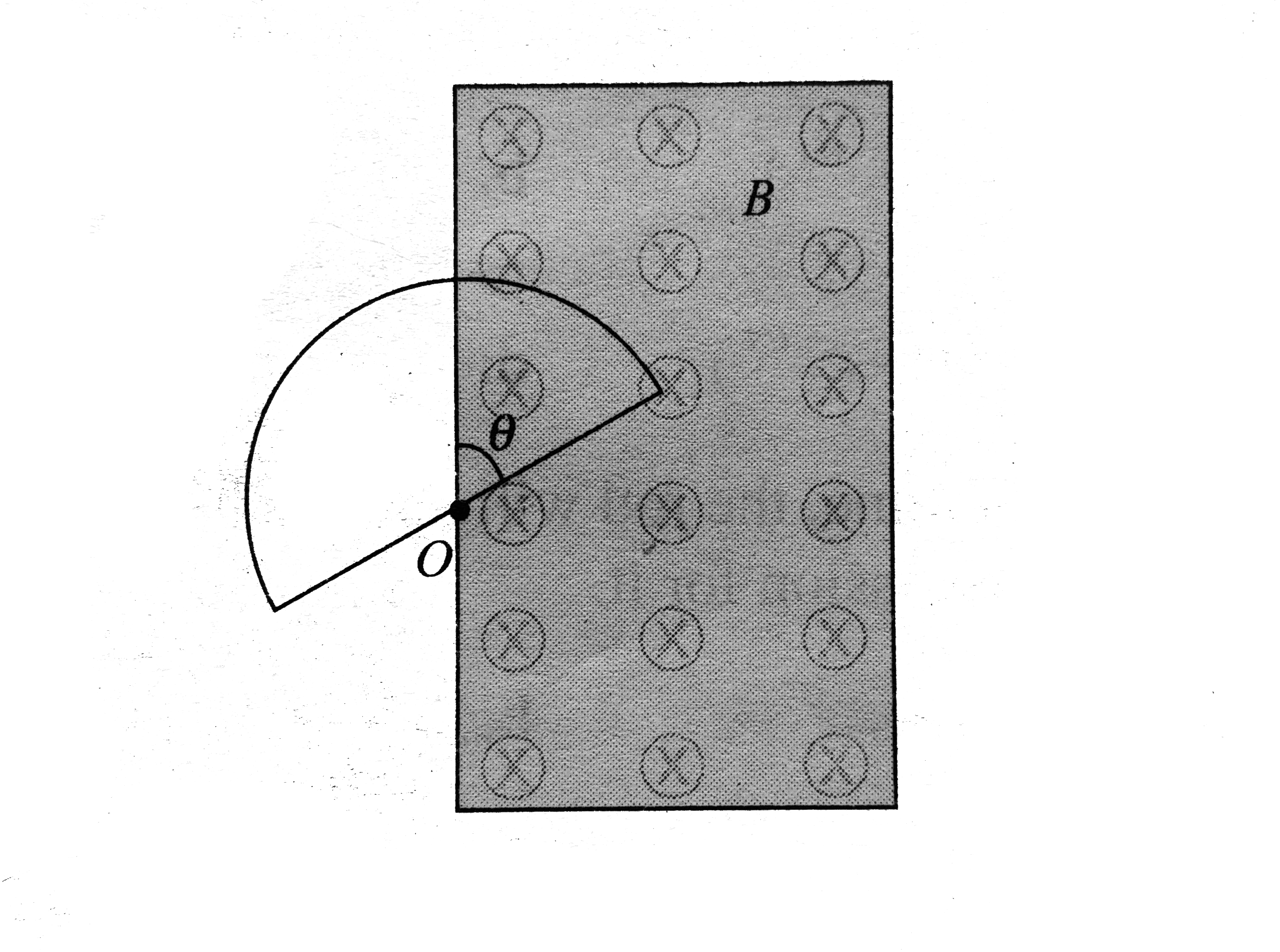
The variation of emf as function of time is View SolutionQuestion 171
A wire loop enclosing a semicircle of radius R islocated on the boundary of a uniform magnetic field B. At the moment t=0, the loop is set into rotation with constant angular acceleration α about an axis O. The clockwise emf direction is taken to be positive.
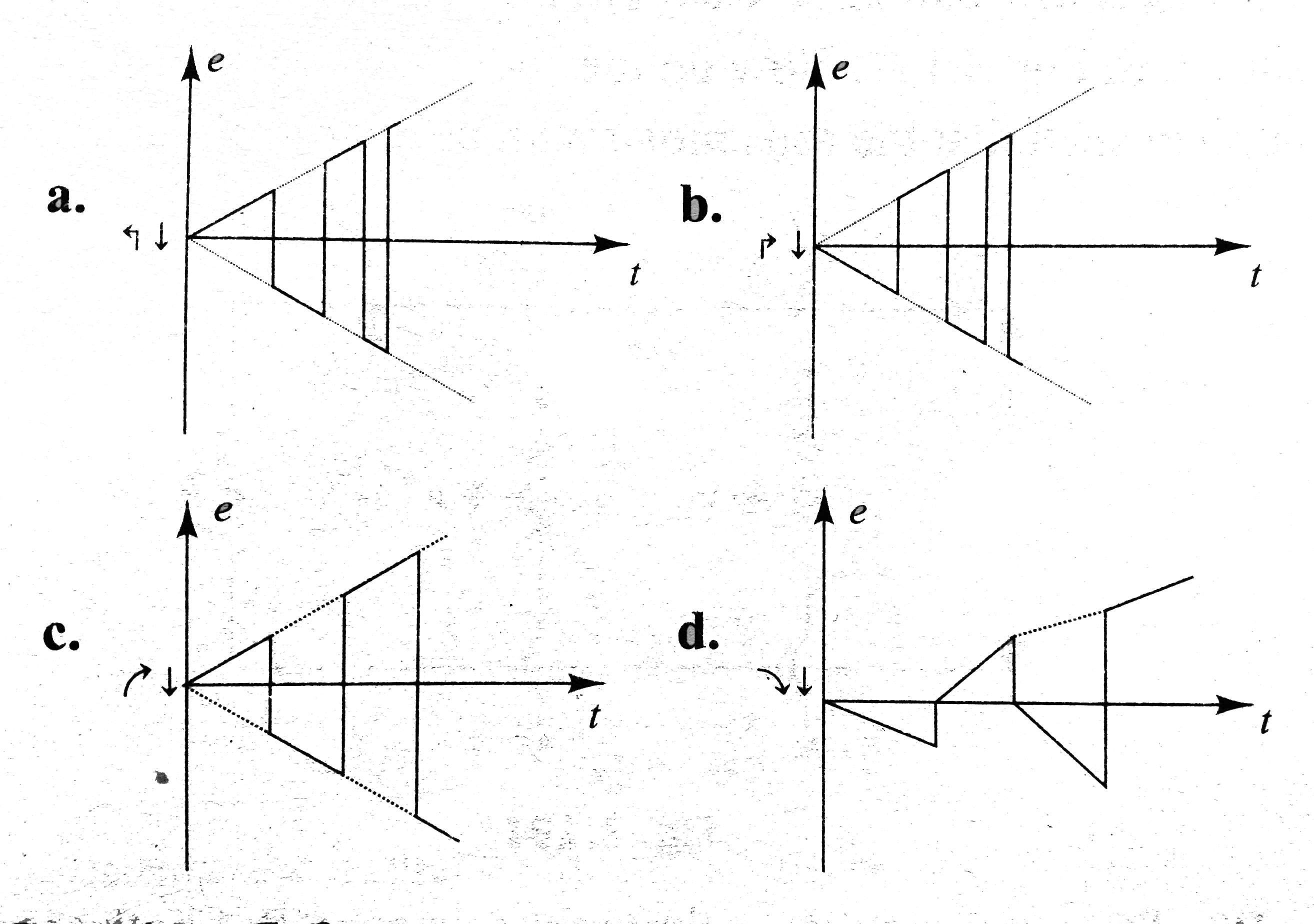
The variation of emf as a function of time is View SolutionQuestion 172
In the circuit shown in Fig. the capacitor has capacitance C=20μF and is initially charged to 100V with the polarity shown. The resistor R0 has resistance 10Ω. At time t=0, the switch is closed. The smaller circuit is not connected in any way to teh larger one. the wire of the smaller circuit has a resistance of 1.0Ωm−1 and contains 25 loops. the larger circuit is a rectangle 2.0m by 4.0m, while the smaller one has dimensions a=10.0cm and b=20.0cm. the distance cis 5.0cm. (The figure is not drawn to scale.) Both circuit are held stationary. Assume that only the wire nearest to teh smaller circuit produces. an appreciable magnetic field through it.
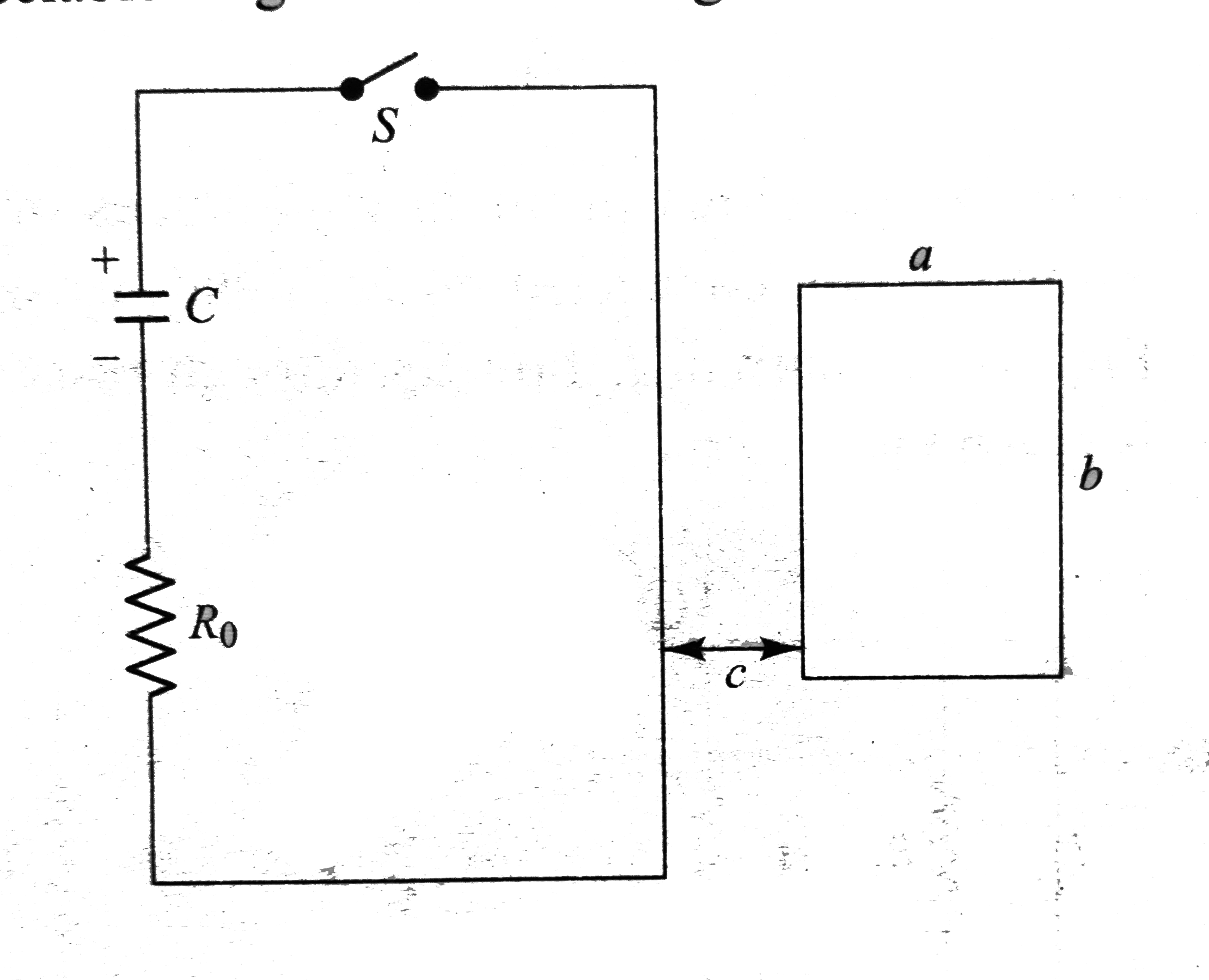
The current in the circuit 200ms after closing S is View SolutionQuestion 173
In the circuit shown in Fig. the capacitor has capacitance C=20μF and is initially charged to 100V with the polarity shown. The resistor R0 has resistance 10Ω. At time t=0, the switch is closed. The smaller circuit is not connected in any way to teh larger one. the wire of the smaller circuit has a resistance of 1.0Ωm−1 and contains 25 loops. the larger circuit is a rectangle 2.0m by 4.0m, while the smaller one has dimensions a=10.0cm and b=20.0cm. the distance cis 5.0cm. (The figure is not drawn to scale.) Both circuit are held stationary. Assume that only the wire nearest to teh smaller circuit produces. an appreciable magnetic field through it.
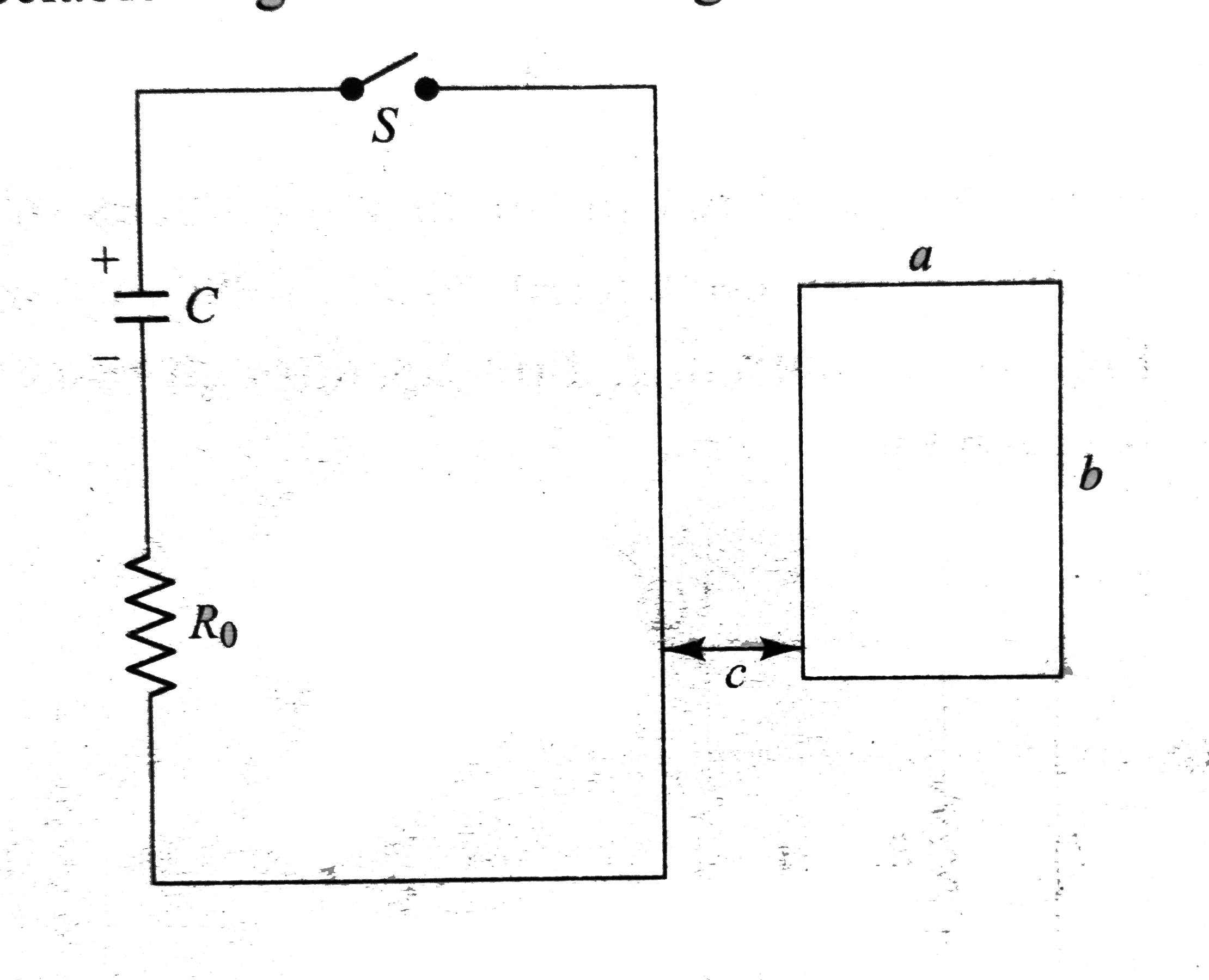
The curent in the smaller circuit 200μs after closing S is View SolutionQuestion 174
In the circuit shown in Fig. the capacitor has capacitance C=20μF and is initially charged to 100V with the polarity shown. The resistor R0 has resistance 10Ω. At time t=0, the switch is closed. The smaller circuit is not connected in any way to teh larger one. the wire of the smaller circuit has a resistance of 1.0Ωm−1 and contains 25 loops. the larger circuit is a rectangle 2.0m by 4.0m, while the smaller one has dimensions a=10.0cm and b=20.0cm. the distance cis 5.0cm. (The figure is not drawn to scale.) Both circuit are held stationary. Assume that only the wire nearest to teh smaller circuit produces. an appreciable magnetic field through it.
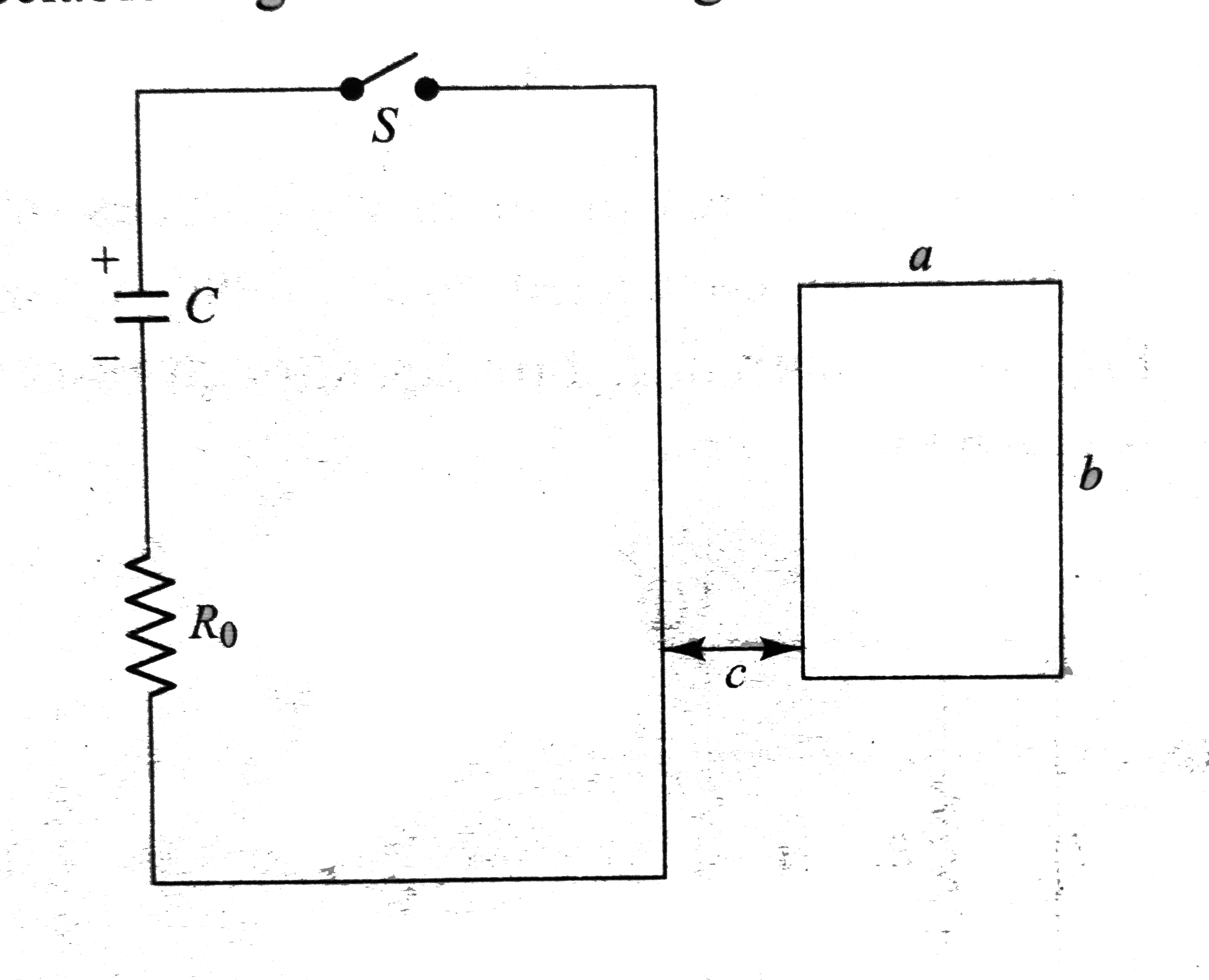
The direction of current in the smaller circuit is View SolutionQuestion 175
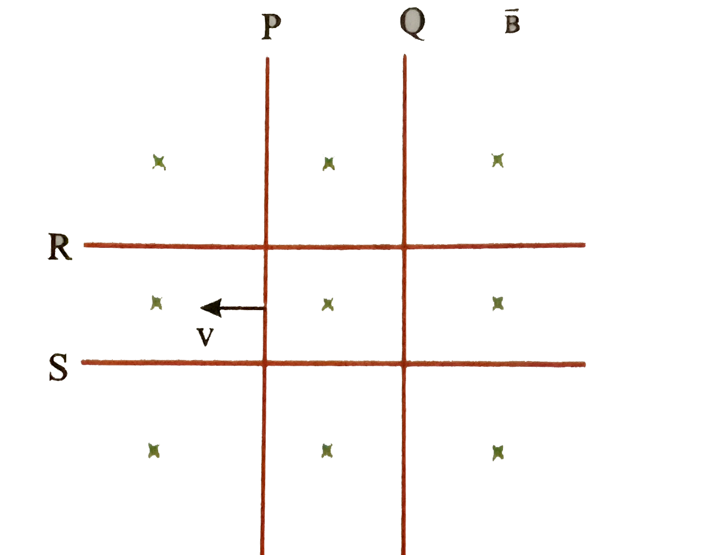
Two long parallel conducting rails are placed in a uniform magnetic field. On one side, the rails are connected with a resistance R. Two rods MNandM'N' each having resistance r are placed as showing in Fig. Now on the rods MNandM'N' forces are applied such that the rods move with constant velocity v.
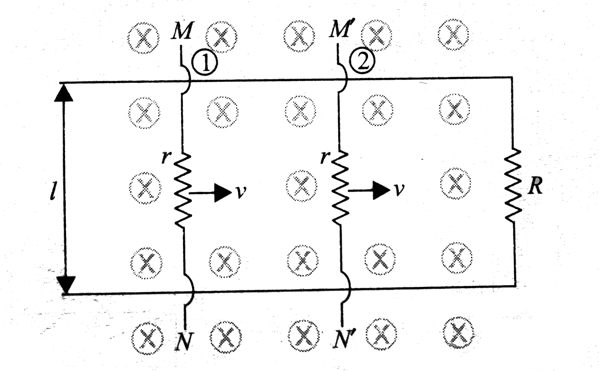
The current flowing through resustance R if both the rods move with the same speed v toward right is View SolutionQuestion 176
Two long parallel conducting rails are placed in a uniform magnetic field. On one side, the rails are connected with a resistance R. Two rods MNandM'N' each having resistance r are placed as showing in Fig. Now on the rods MNandM'N' forces are applied such that the rods move with constant velocity v.
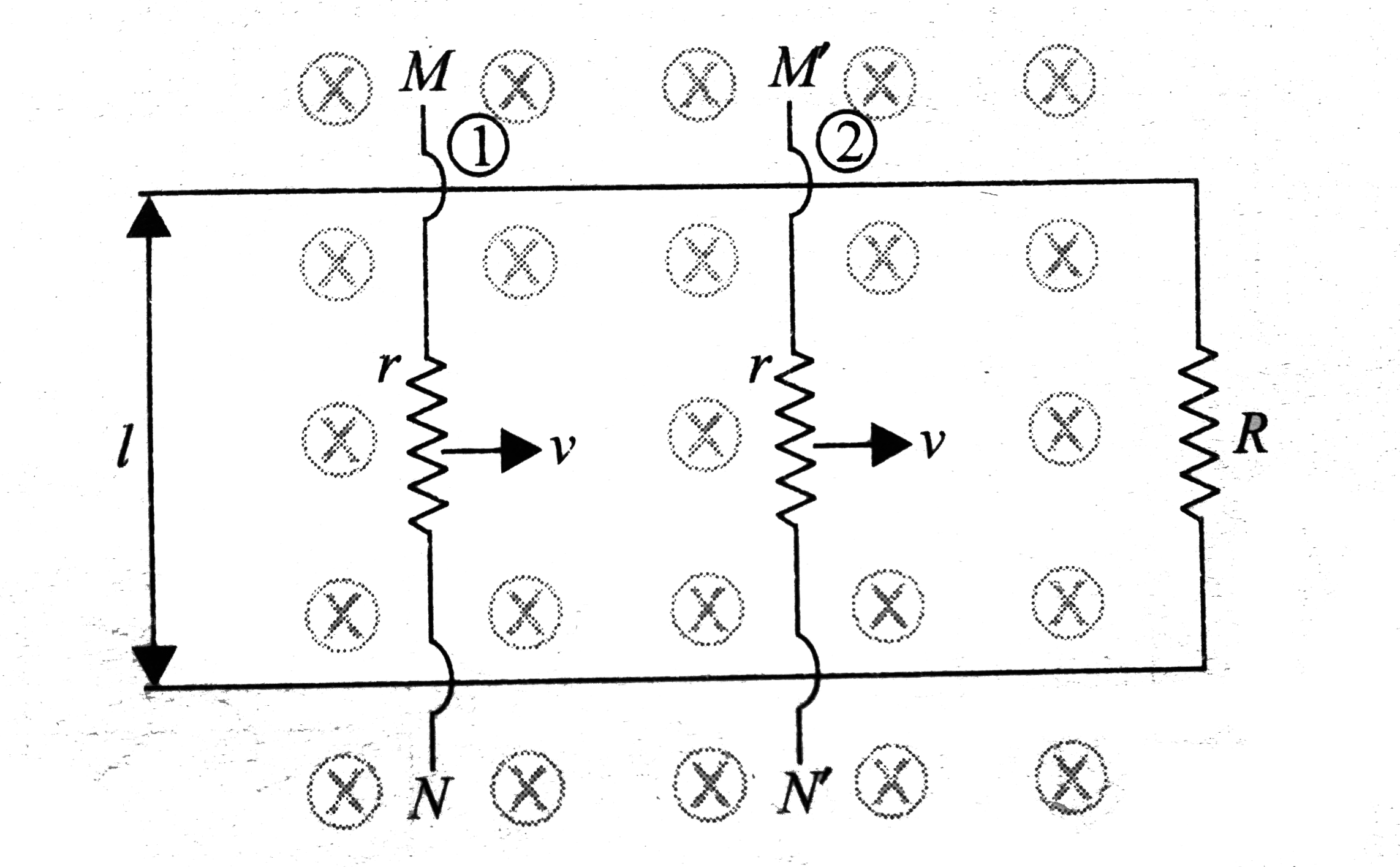
(i). The current flowing through resistance R if the rod Mn moves toward left and the rod M'N' moves toward the right is View SolutionQuestion 177
Two long parallel conducting rails are placed in a uniform magnetic field. On one side, the rails are connected with a resistance R. Two rods MNandM'N' each having resistance r are placed as showing in Fig. Now on the rods MNandM'N' forces are applied such that the rods move with constant velocity v.
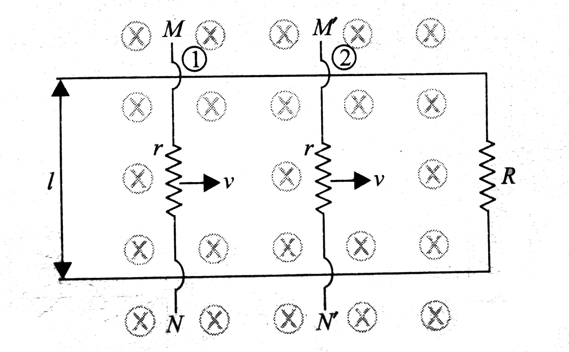
(ii). If in the previous problem resistance of values R1andR2 are connected on both ends as shown in Fig. current I, flowing through resistance R1 is given by View SolutionQuestion 181
In Fig. shown, the rod has a resistance R, the horizontal rails have negligible friction. A battery of emf E and negligible internal resistance is connected between points aandb. The rod is released from rest.
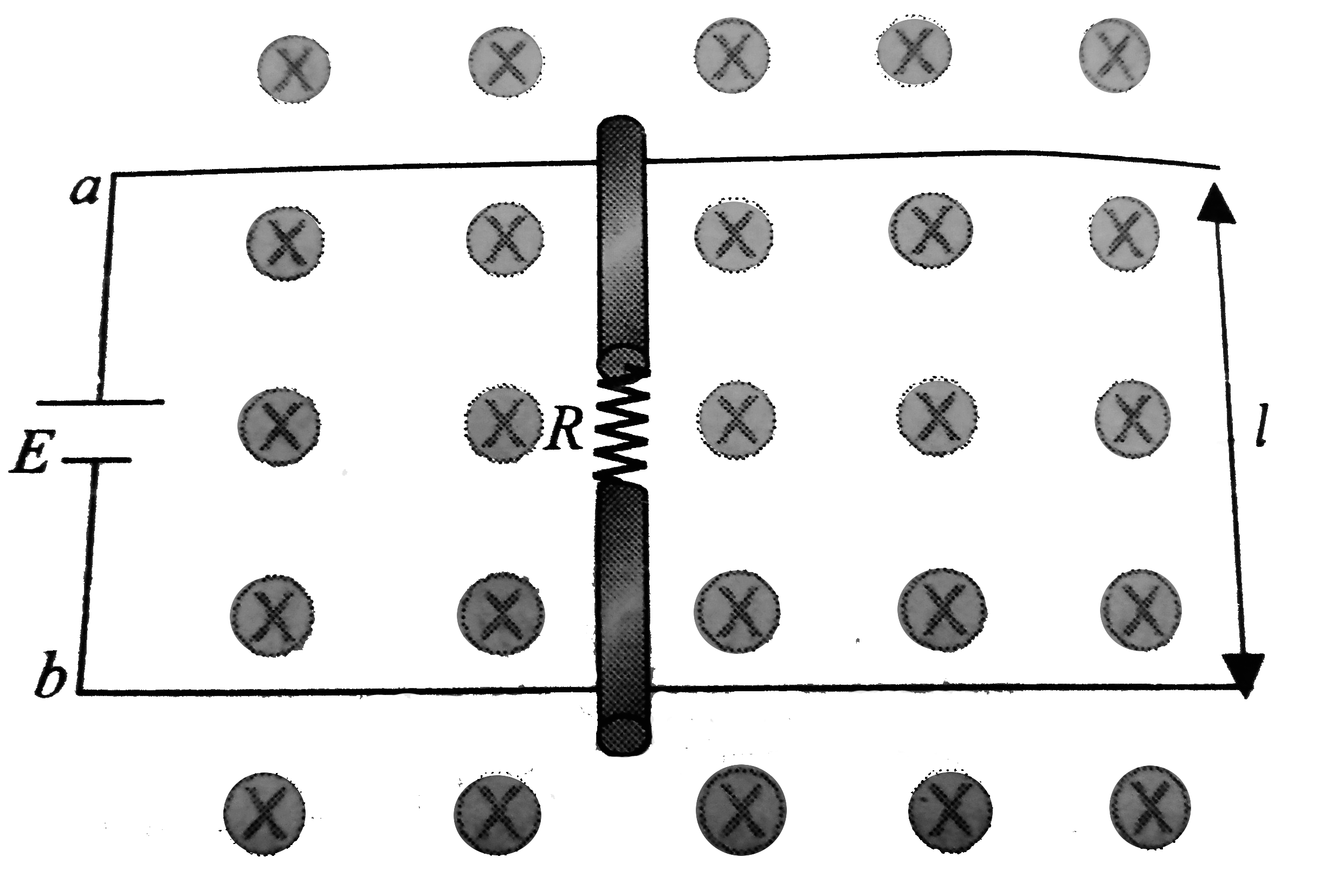
after some time, the rod will approach a terminal speed . Find an expression for it. View SolutionQuestion 188
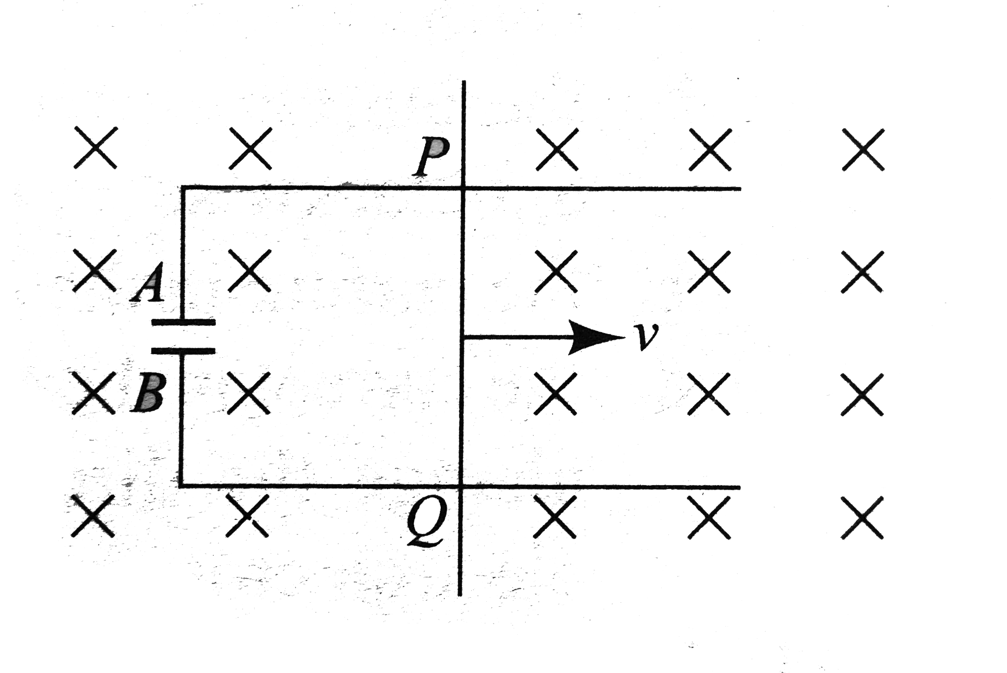
A standing wave y=2Asinkxcosωt is set up in the wire AB fixed at both ends by two vertical walls (see Fig. 3.197). The region between the walls contains a constant magnetic field B. Now answer the following question:
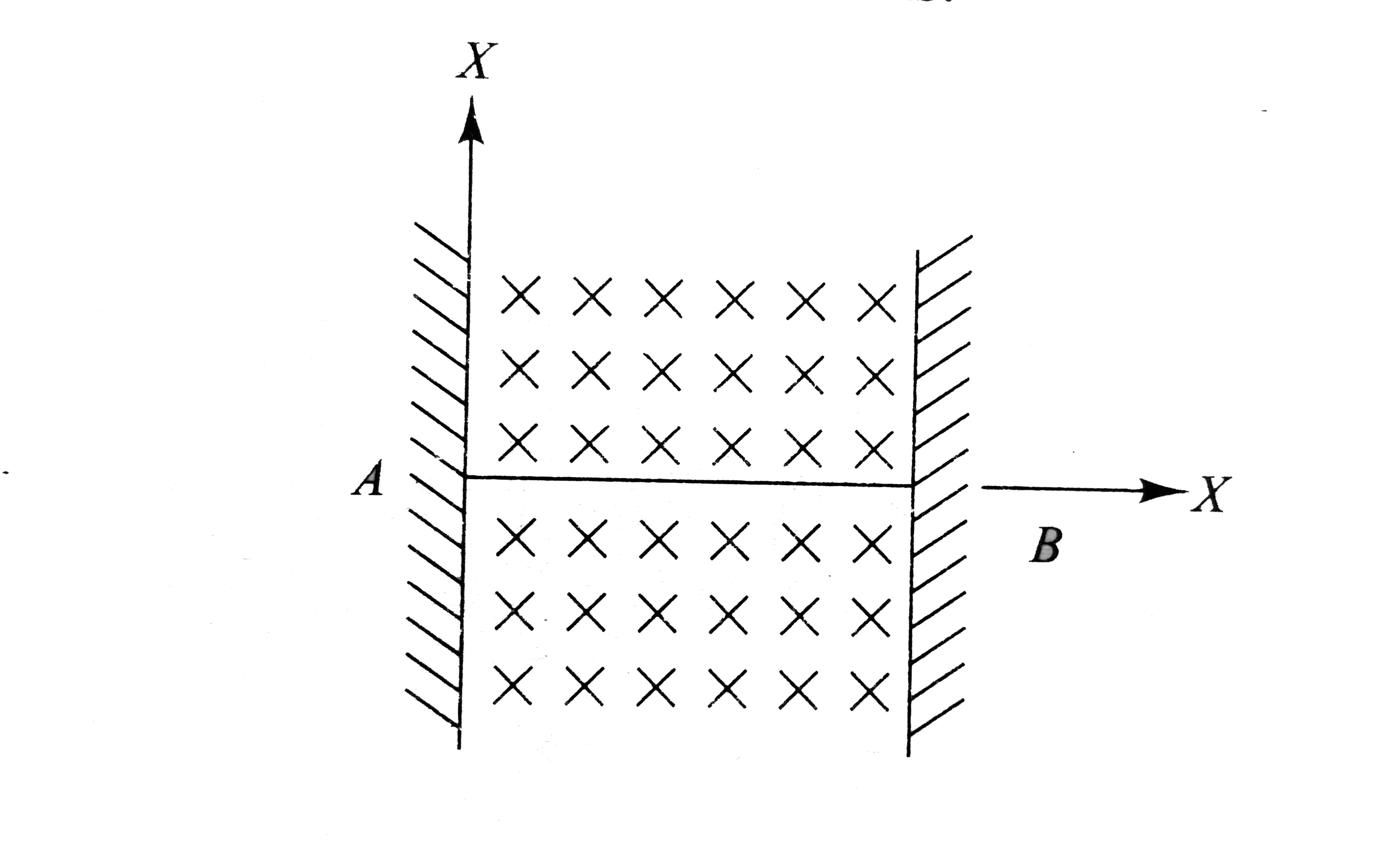
The wire is found to vibrate in the third harmonic. The maximum emf induced is View SolutionQuestion 189
A stsnding wave y=2Asinkxcosωt is set up in the wire AB fixed at both ends by two vertical walls (see Fig. 3.197). The region between the walls contains a constant magnetic field B. Now answer the following question:
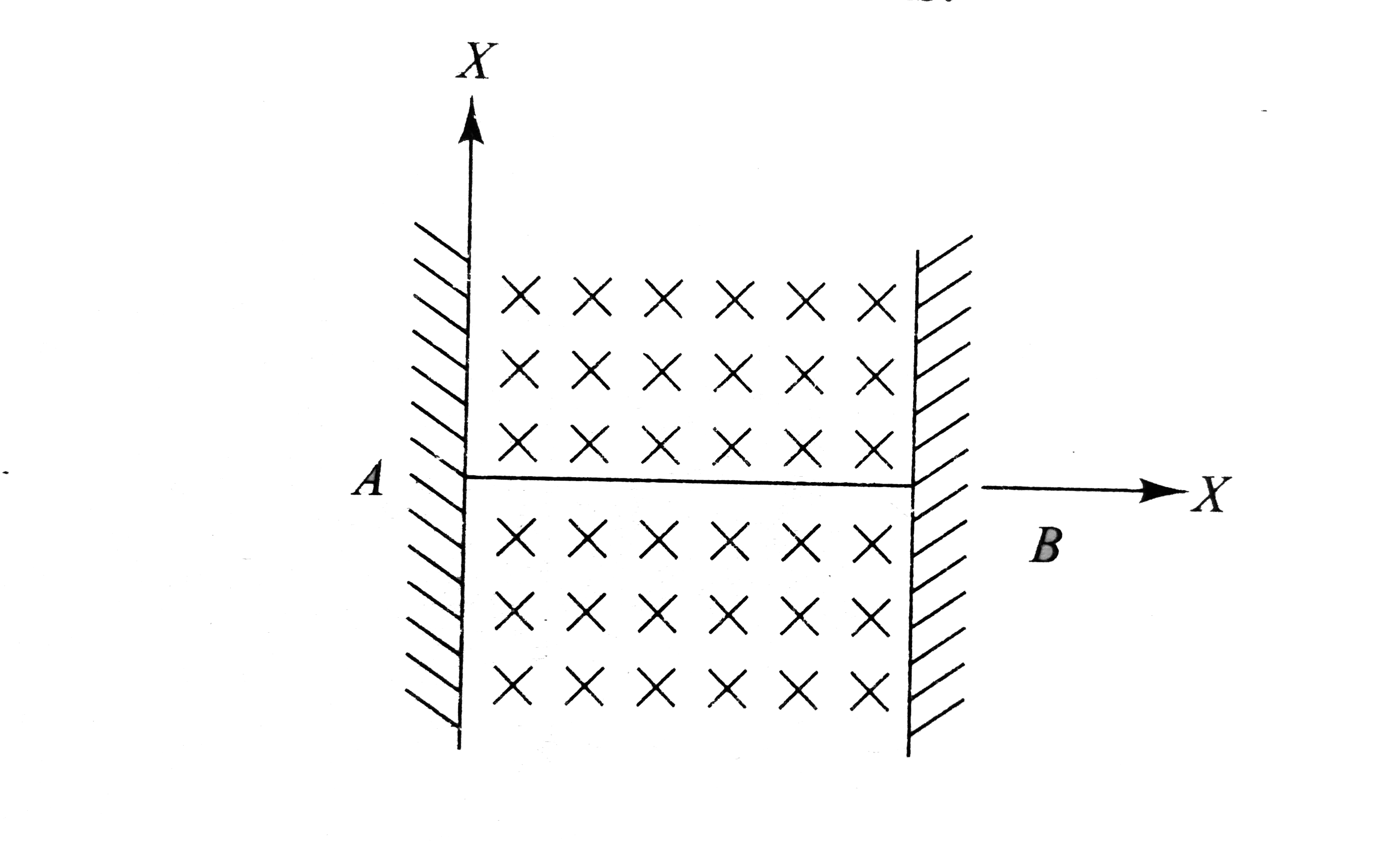
In the above qestion, the time when the emf becomes maximum for the time is View SolutionQuestion 190
A stsnding wave y=2Asinkxcosωt is set up in the wire AB fixed at both ends by two vertical walls (see Fig. 3.197). The region between the walls contains a constant magnetic field B. Now answer the following question:
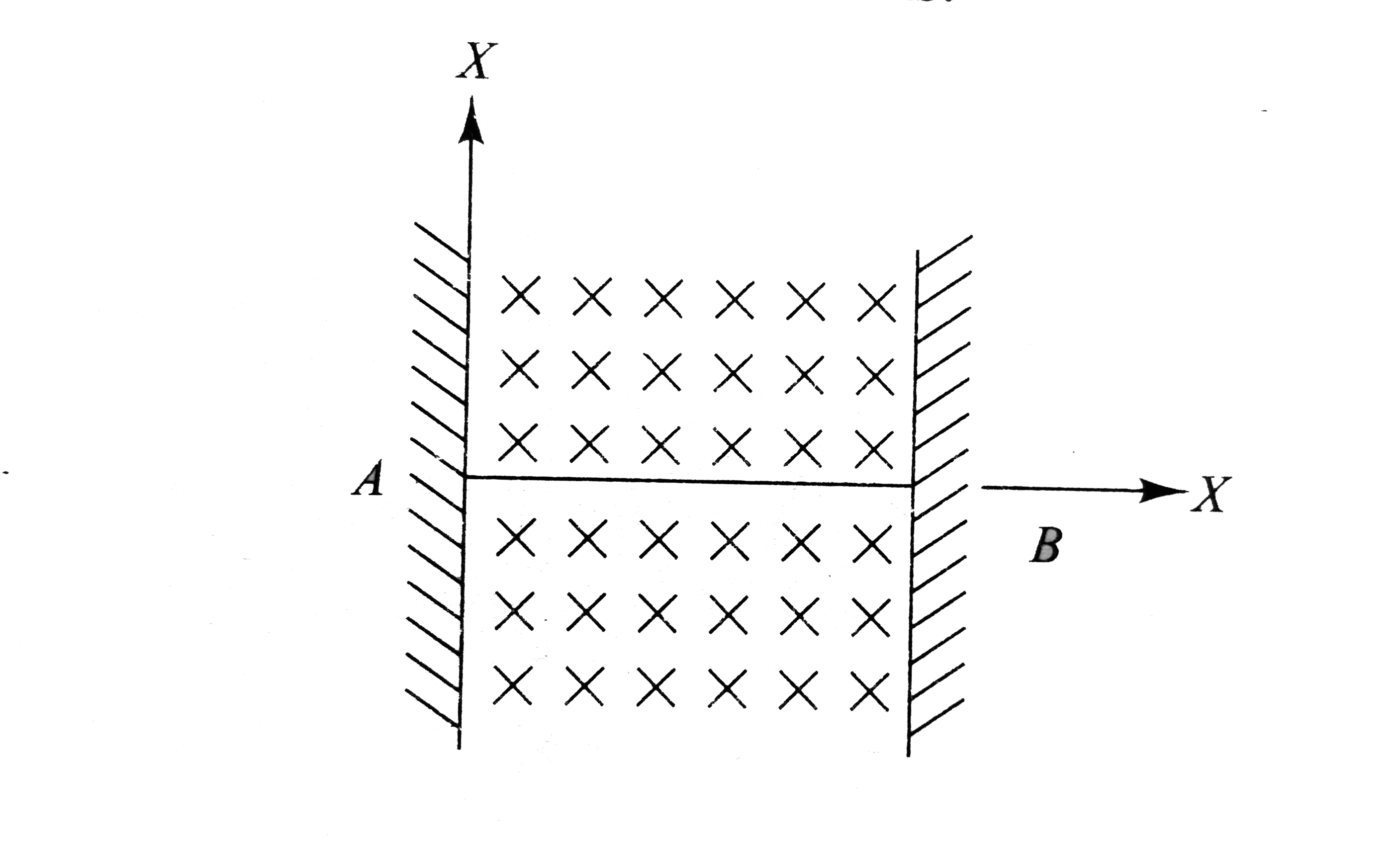
In which of the following modes the emf induced in AB is always zero?View SolutionQuestion 191
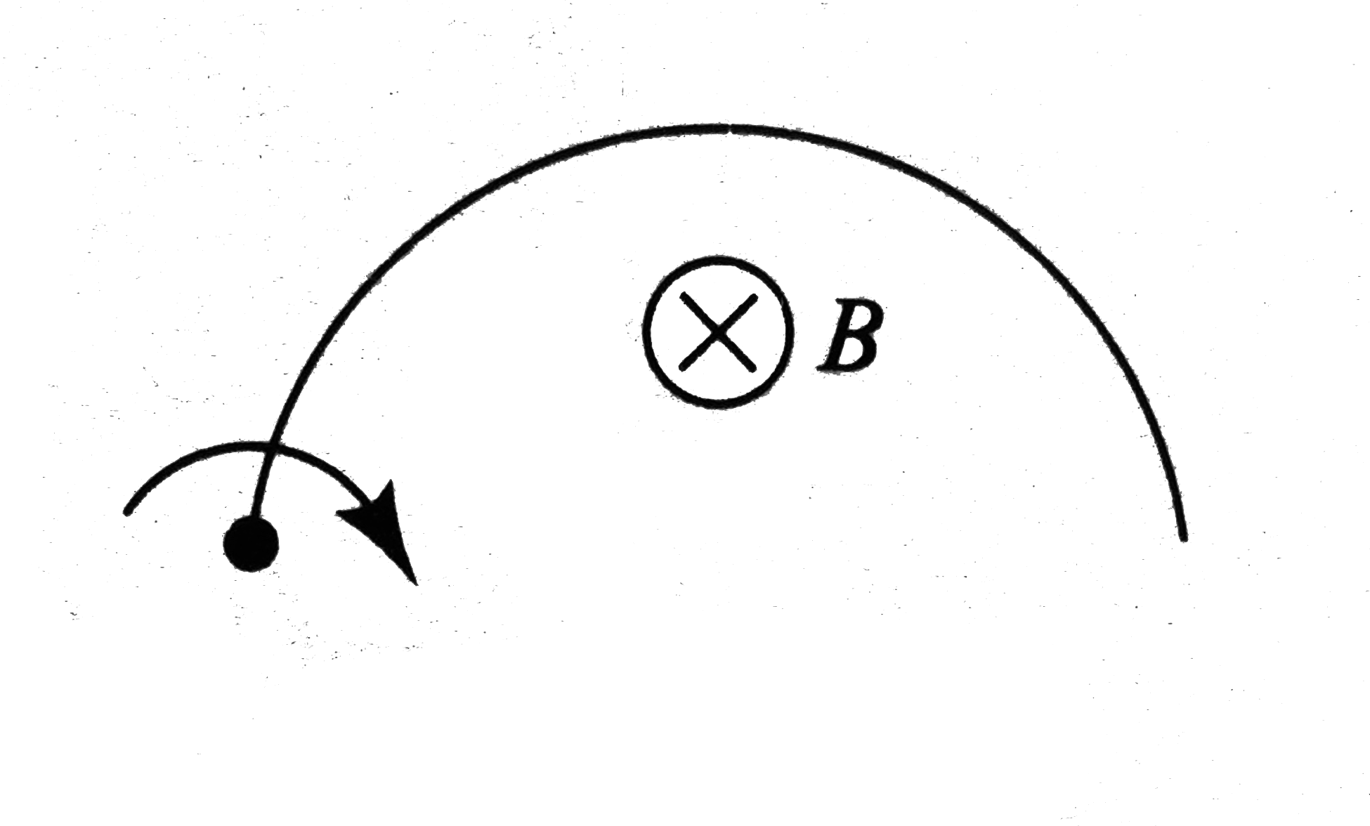
A fan operates at 200 volt (DC) consuming 1000W when running at full speed . It's internal wiring has resistance 1Ω . When the fan runs at full speed , its speed becomes constant. This is because the torque due to magnetic field inside tha fan is balanced by the torque due to air resistance on the blades of the fan and torque due to friction between the fixed part and the shaft of the fan. The electrical power going into the fan is spent (i) in the internal resistance as heat, call it P1(ii) in doing work against internal friction and air resistance producing heat, sound etc. call it P2. When the coil of fan rotates, an emf is also induced in the coil. This opposes the external emf applied to snd the current into the fan. This emf is called back-emf,call it 'e'.
Answer the following questions when the fan is running at full speed.
The current flowing into the fan and the value of back emf e is View SolutionQuestion 192
A fan operates at 200 volt (DC) consuming 1000W when running at full speed . It's internal wiring has resistance 1Ω . When the fan runs at full speed , its speed becomes constant. This is because the torque due to magnetic field inside tha fan is balanced by the torque due to air resistance on the blades of the fan and torque due to friction between the fixed part and the shaft of the fan. The electrical power going into the fan is spent (i) in the internal resistance as heat, call it P1(ii) in doing work against internal friction and air resistance producing heat, sound etc. call it P2. When the coil of fan rotates, an emf is also induced in the coil. This opposes the external emf applied to snd the current into the fan. This emf is called back-emf,call it 'e'.
Answer the following questions when the fan is running at full speed.
The value of power P1 is View SolutionQuestion 193
A fan operates at 200 volt (DC) consuming 1000W when running at full speed . It's internal wiring has resistance 1Ω . When the fan runs at full speed , its speed becomes constant. This is because the torque due to magnetic field inside tha fan is balanced by the torque due to air resistance on the blades of the fan and torque due to friction between the fixed part and the shaft of the fan. The electrical power going into the fan is spent (i) in the internal resistance as heat, call it P1(ii) in doing work against internal friction and air resistance producing heat, sound etc. call it P2. When the coil of fan rotates, an emf is also induced in the coil. This opposes the external emf applied to snd the current into the fan. This emf is called back-emf,call it 'e'.
Answer the following questions when the fan is running at full speed.
The value of power P2 si View SolutionQuestion 194
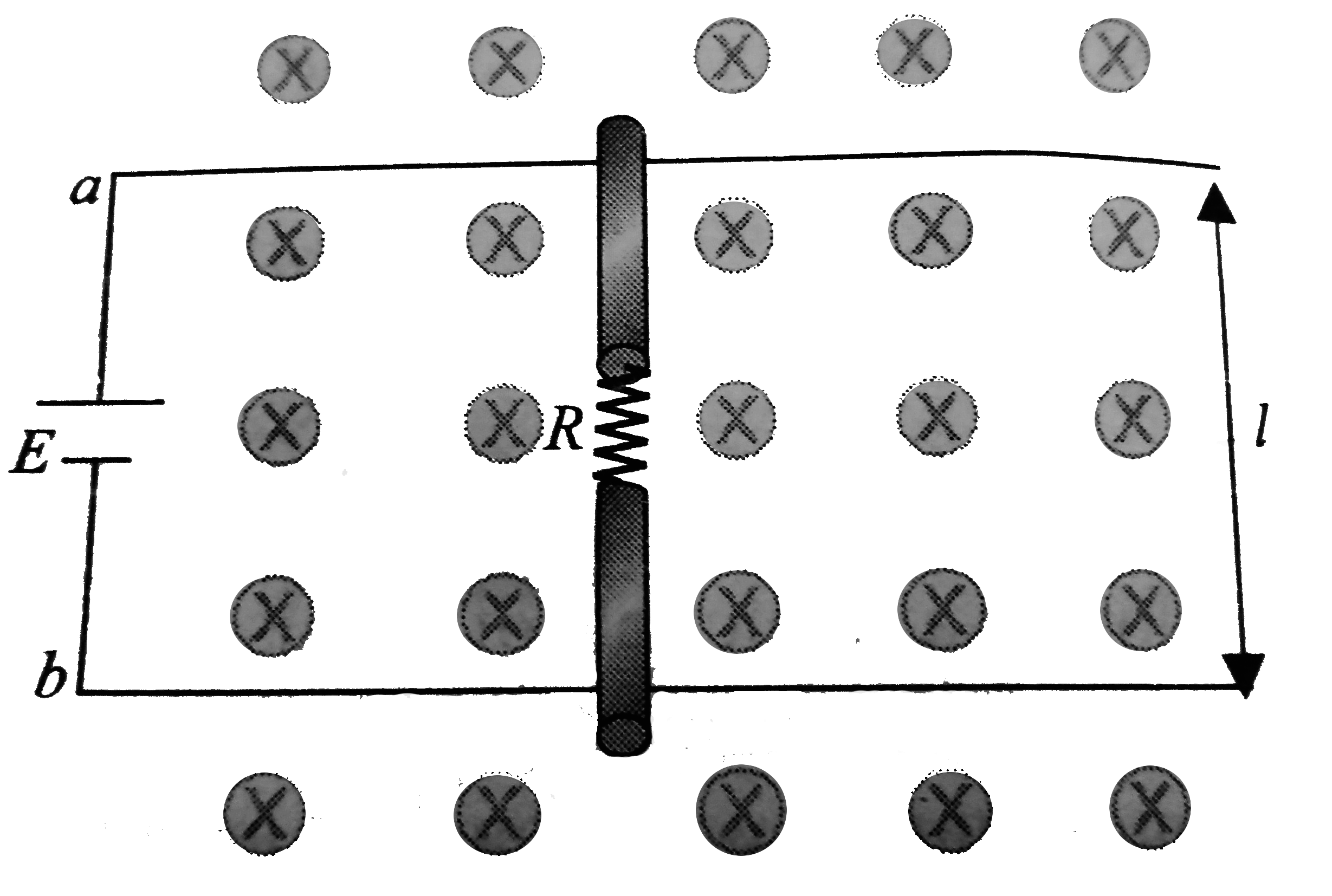
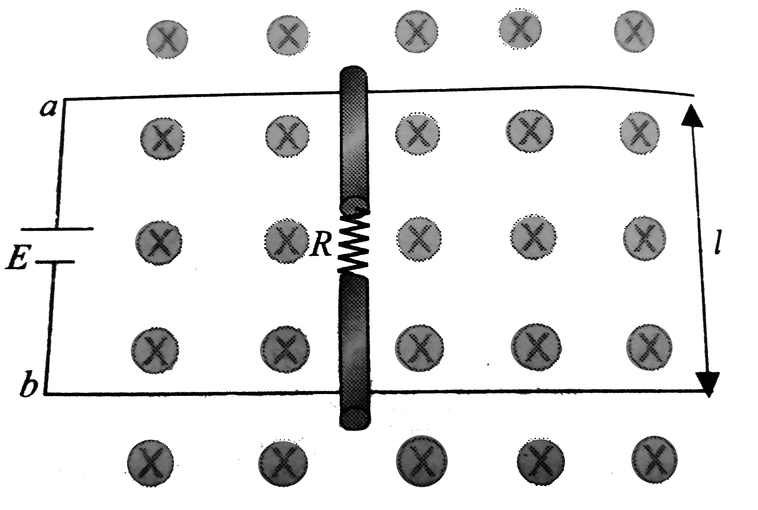
Figure shows a conducting rod of negligible resistance that can slide on smooth U-shaped rail made of wire of resistance 1Ω/m. Position of the conducting rod at t=0 is shown. A time dependent magnetic field B=2t tesla is switched on at t=0
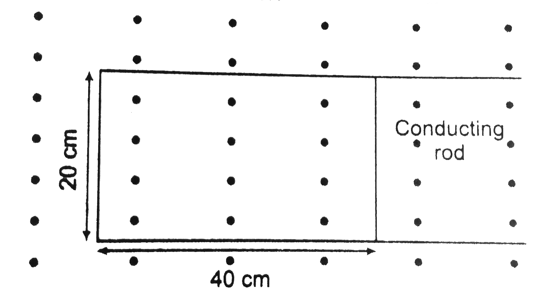
The current in the loop at t=0 due to induced emf isView SolutionQuestion 195
Figure shows a conducting rod of negligible resistance that can slide on smooth U-shaped rail made of wire of resistance 1Ω/m. Position of the conducting rod at t=0 is shown. A time dependent magnetic field B=2t tesla is switched on at t=0
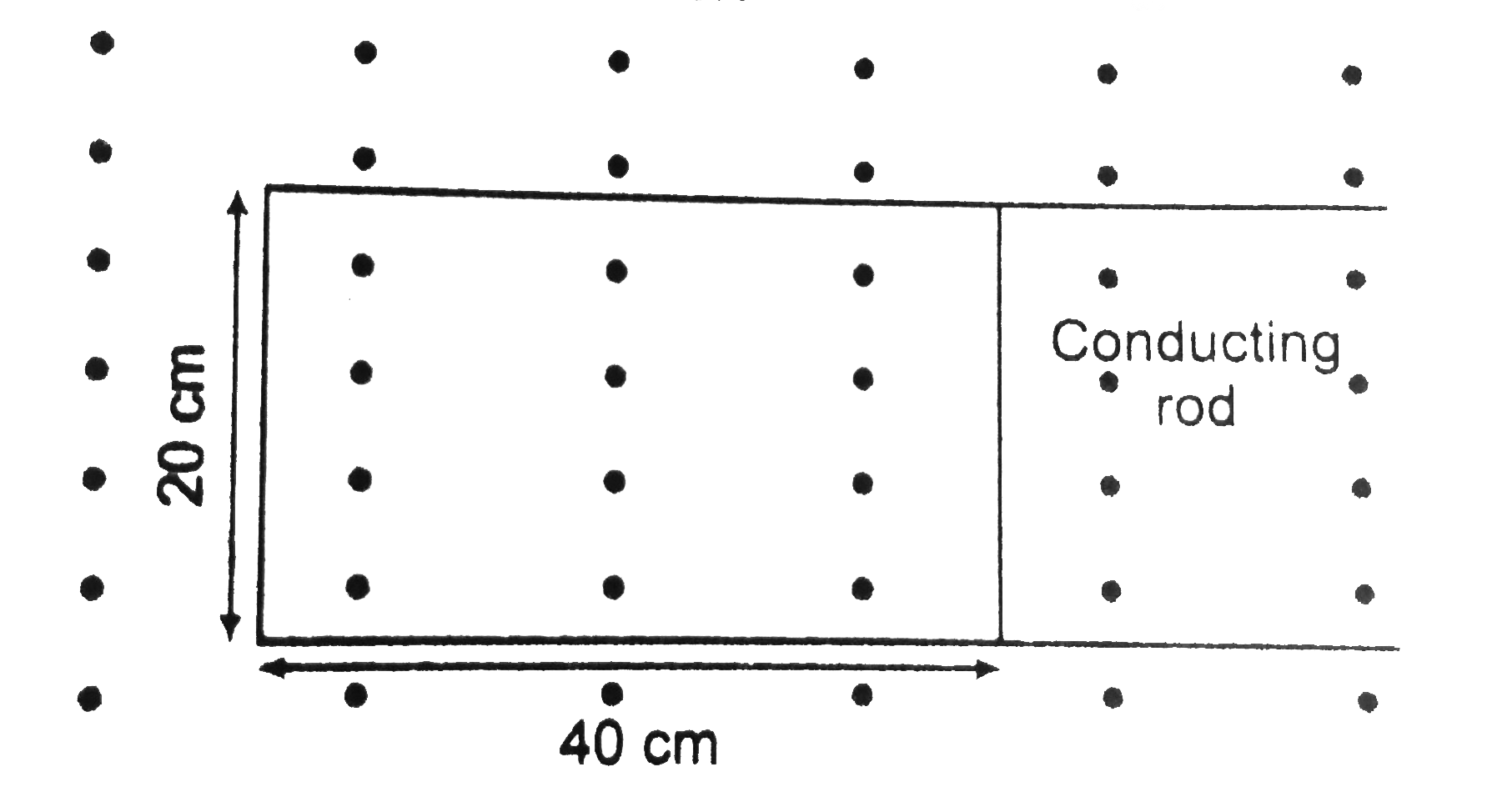
At t=0, when the magnetic field is switched on, the conducting rod is moved to the left at constant speed 5cm/s by some external means. At t=2s, net induced emf has magnitudeView SolutionQuestion 196
Figure shows a conducting rod of negligible resistance that can slide on smooth U-shaped rail made of wire of resistance 1Ω/m. Position of the conducting rod at t=0 is shown. A time dependent magnetic field B=2t tesla is switched on at t=0
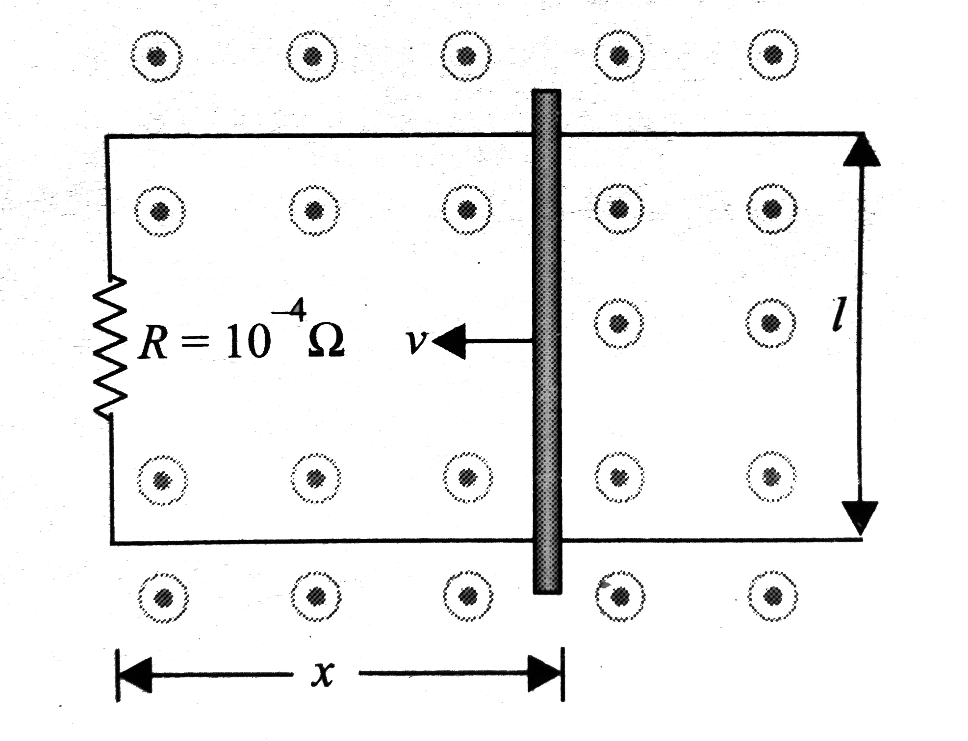
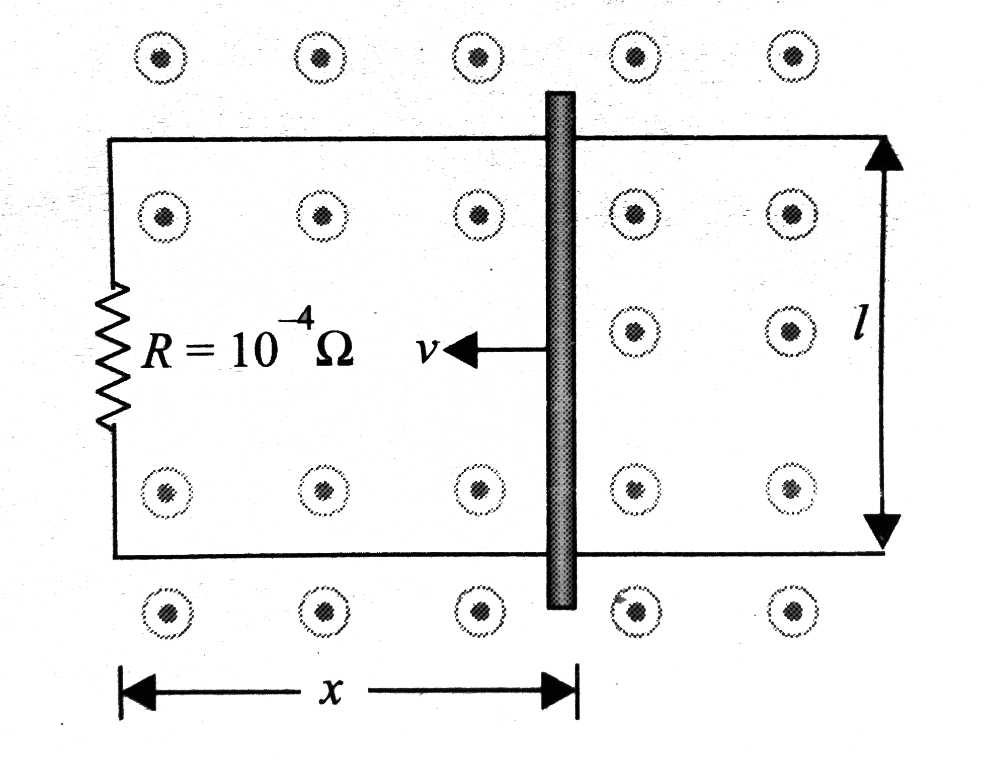
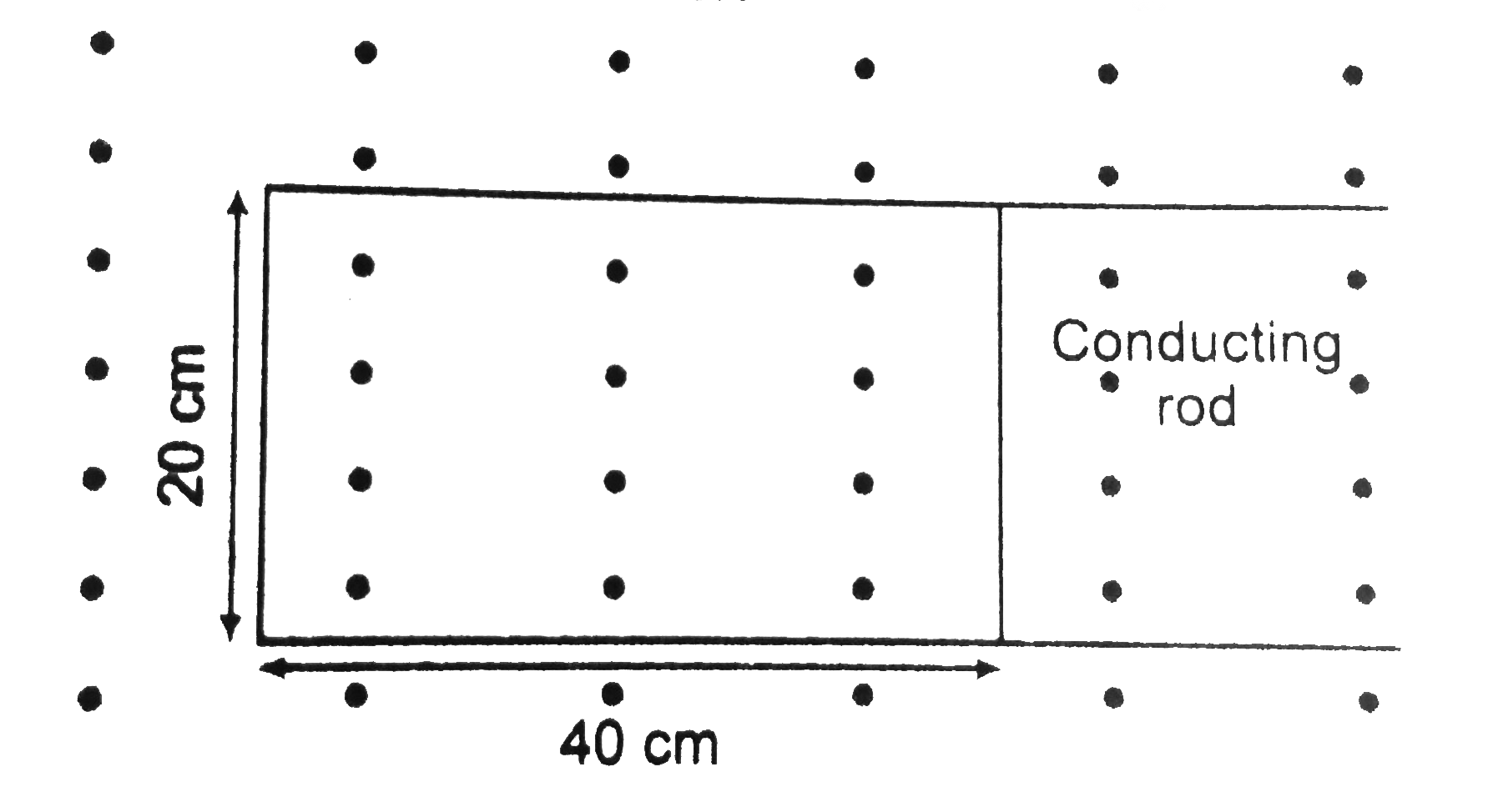 The magnitude of the force required to move the conducting rod at constant speed 5cm/s at the same instant t=2s, is equal toView Solution
Question 197
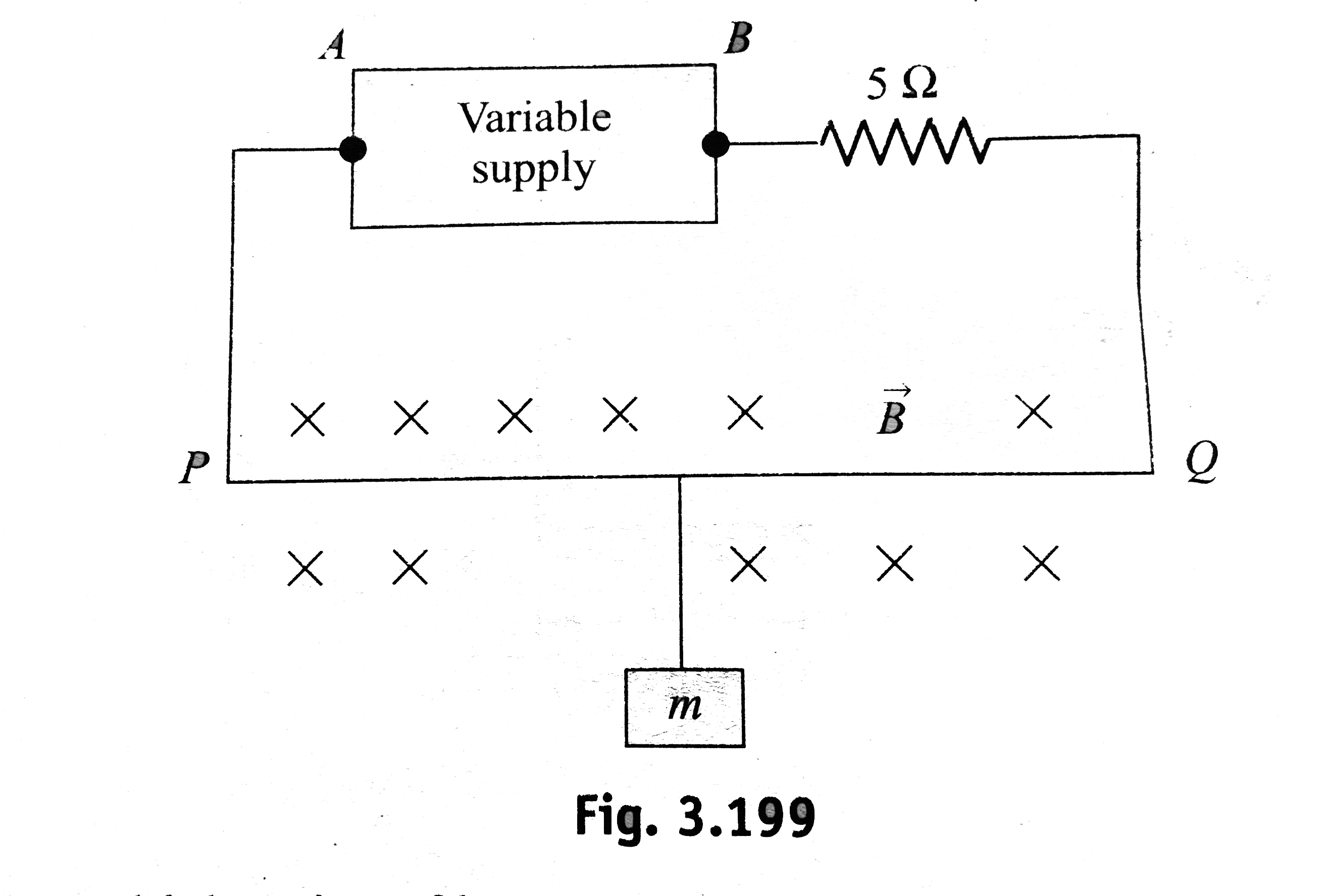
A brilliant student of physics developed a magnetic balance to weight objects. The mass m to be measured is hung from the center the bar. Bar is kept in a uniform magnetic field of 1.5T directed into the plane of the figure. Battery voltage can be adjusted to vary the current in the circuit. The horizontal bar shown is 60cm long and is made of extremly light weight material. It is connected to the battery via a resistance. There is no tension in the supporting wired. The magnetic force only supports the hanging weight.
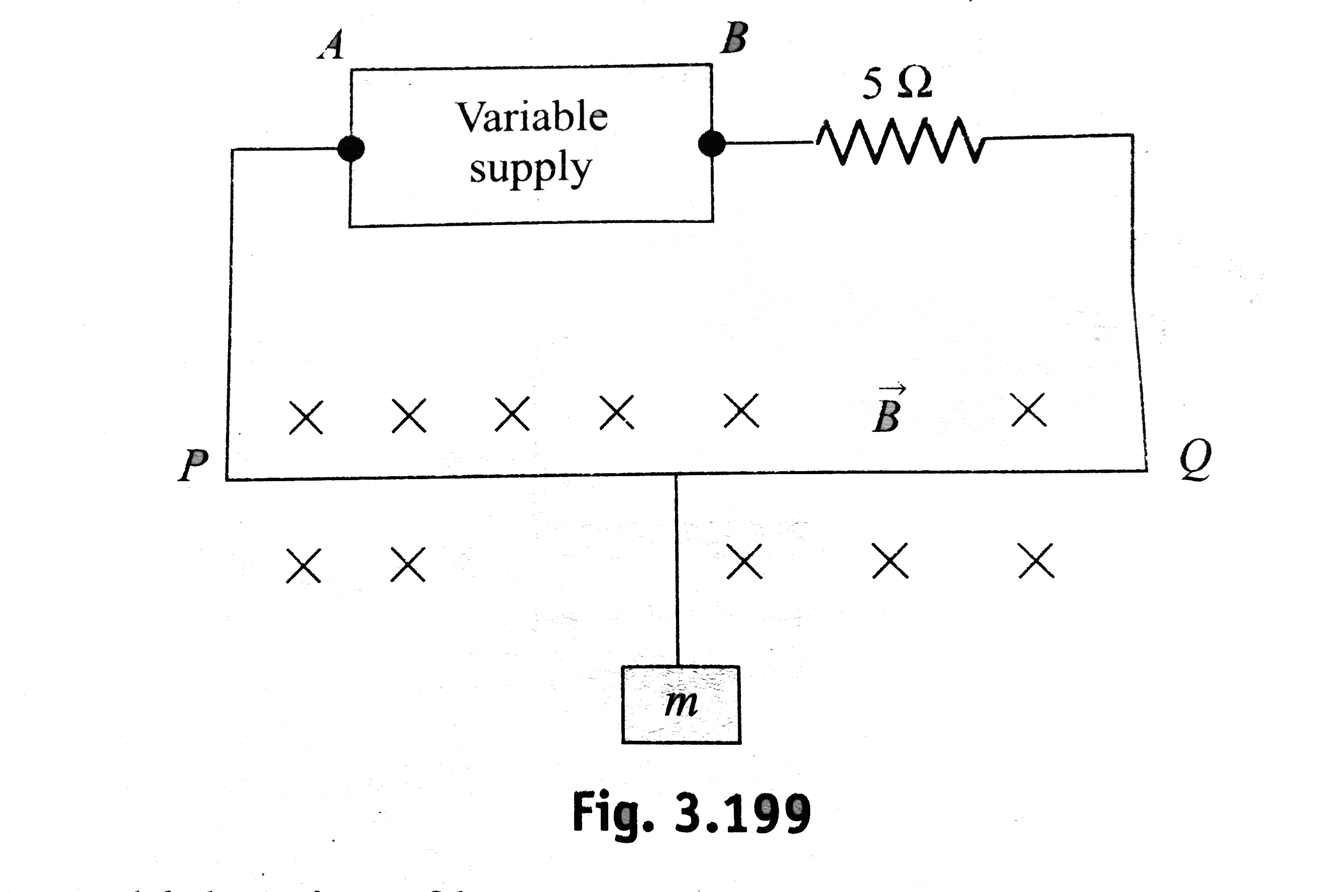
Which point of battery is positive? View SolutionQuestion 198
A brilliant student of physics developed a magnetic balance to weight objects. The mass m to be measured is hung from the center the bar. Bar is kept in a uniform magnetic field of 1.5T directed into the plane of the figure. Battery voltage can be adjusted to vary the current in the circuit. The horizontal bar shown is 60cm long and is made of extremly light weight material. It is connected to the battery via a resistance. There is no tension in the supporting wired. The magnetic force only supports the hanging weight.
If V=150V, what is the maximum mass m ?View SolutionQuestion 199
Consider two parallel conducting frictionless tracks kept in a gravity-free space as shown in Fig. 3.200. A movable conducting PQ, initially kept at OA, is given a velocity 10ms−1 toward right. The space contains a magnetic field which depends upon the distance moved by conductor PQ from the OA line and given by
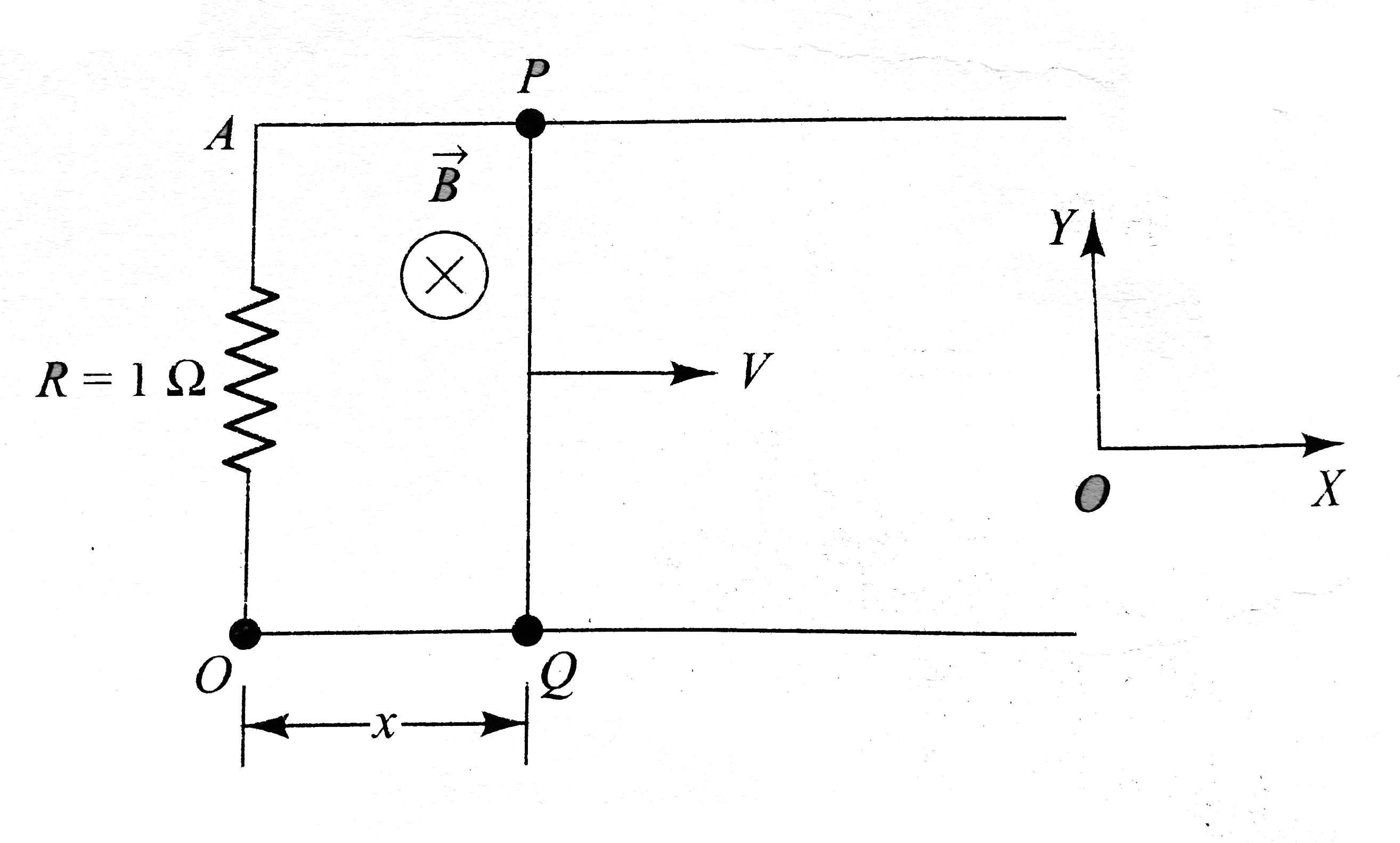
→B=cx(−ˆk)[c=constant=1SIunit]
The mass of the conductor PQ is 1kg and length of PQ is 1m. Answer the following question based on the passage.
The distance travelled by the conductor when its speed is 5ms−1 isView SolutionQuestion 200
Consider two parallel conducting frictionless tracks kept in a gravity-free space as shown in Fig. 3.200. A movable conducting PQ, initially kept at OA, is given a velocity 10ms−1 toward right. The space contains a magnetic field which depends upon the distance moved by conductor PQ from the OA line and given by
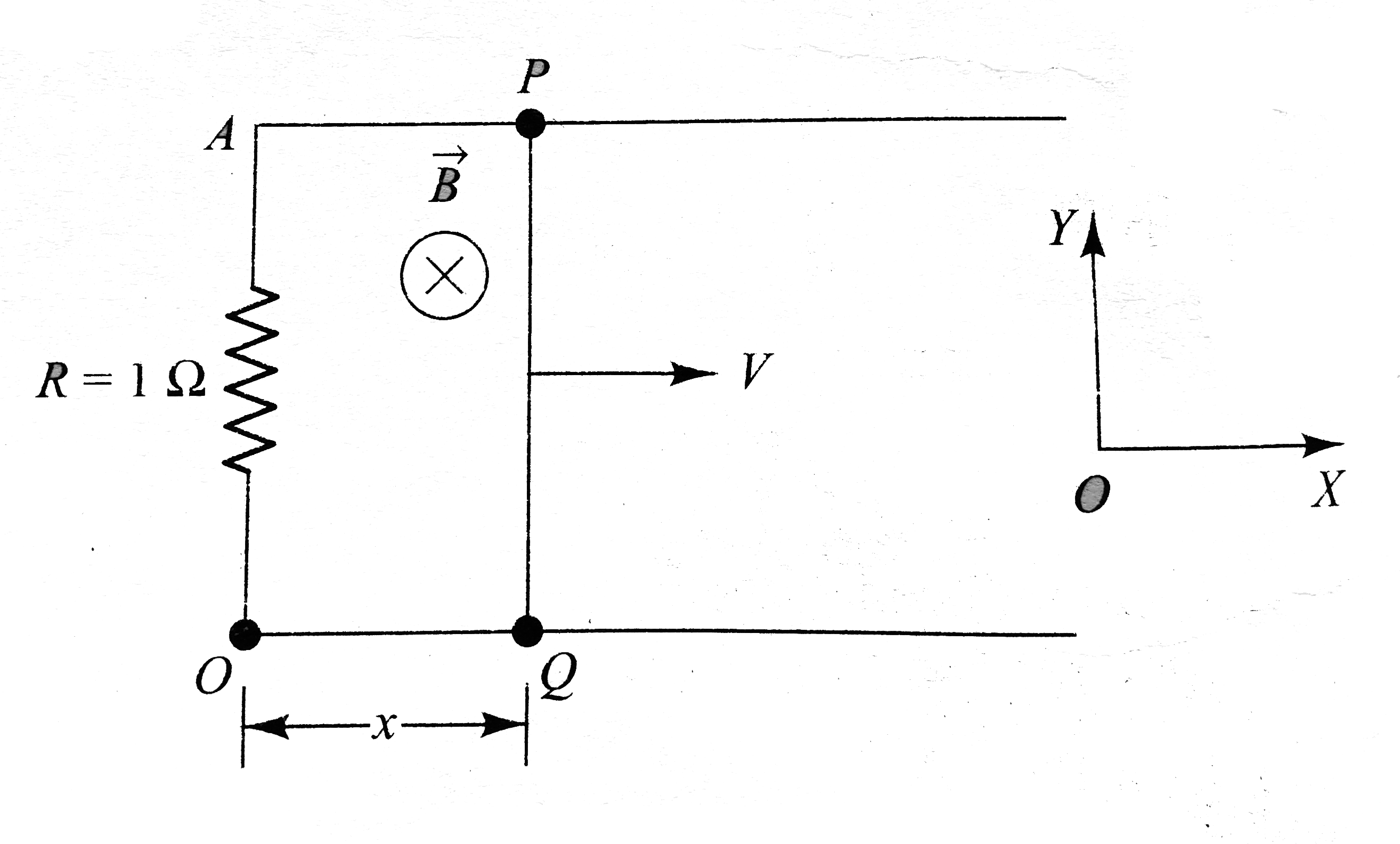
→B=cx(−ˆk)[c=constant=1SIunit]
The mass of the conductor PQ is 1kg and length of PQ is 1m. Answer the following question based on the passage.
The loss during the time interval t=0 to time t seconds when the speed of the conductor is 5ms−1 is View SolutionQuestion 201
Consider two parallel conducting frictionless tracks kept in a gravity-free space as shown in Fig. 3.200. A movable conducting PQ, initially kept at OA, is given a velocity 10ms−1 toward right. The space contains a magnetic field which depends upon the distance moved by conductor PQ from the OA line and given by
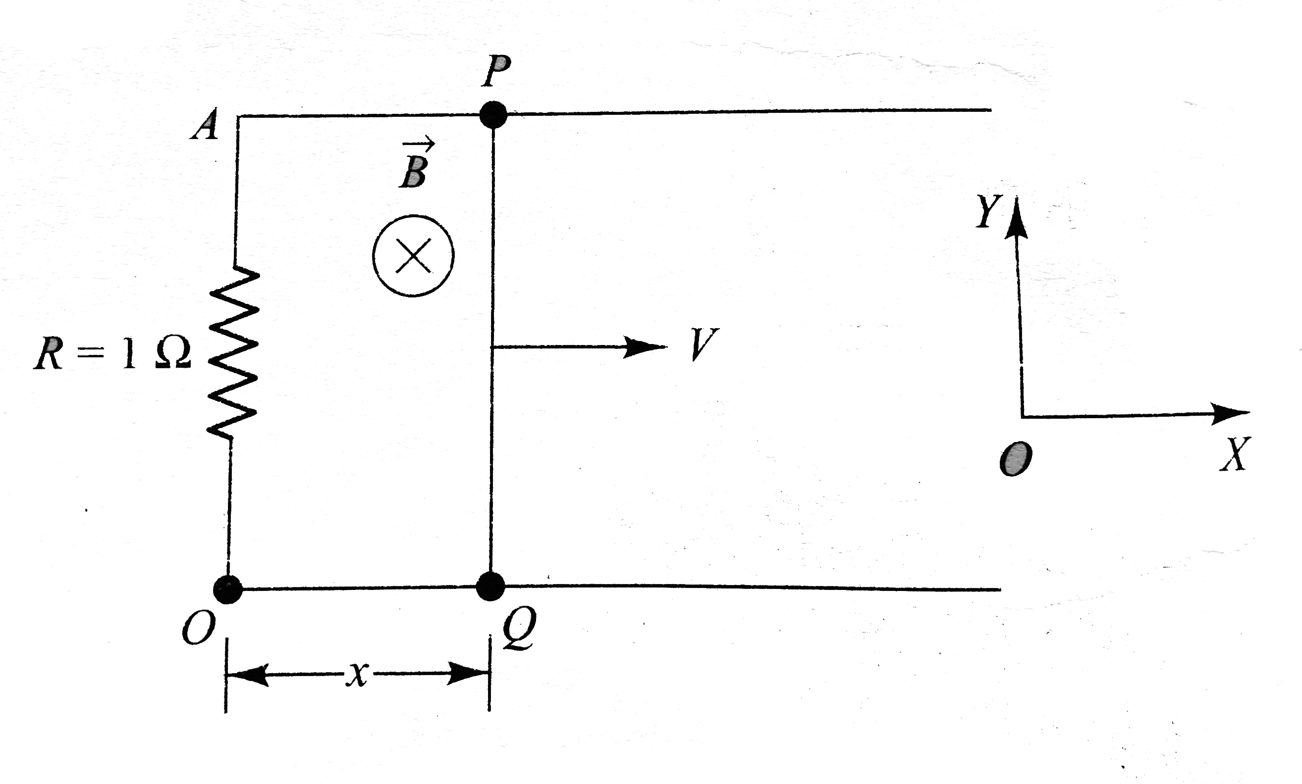
→B=cx(−ˆk)[c=constant=1SIunit]
The mass of the conductor PQ is 1kg and length of PQ is 1m. Answer the following question based on the passage.
The work done by magnetic force acting on the conductor PQ during its motion in the time interval t=0→t=t second when the speed of conductor is 5ms−1 isView SolutionQuestion 202
In Fig. ABCD is a fixed smooth conducting frame in horizontal plane. T is bulb of power 100W,P is a smooth pulley and OQ is a conducting rod. Neglect the self-inductance of the loop and resistance of any part other than the bulb. The mass M is moving down with constant velocity 10ms−1. Bulb lights at its rated power due to induced emf in the loop due to earth's magnetic field. Find the mass M (in kg) of teh block. (g = 10 ms^(2))
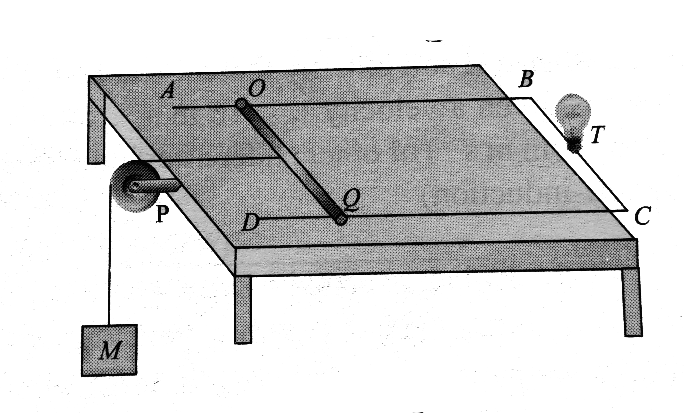 View Solution
Question 203
Figure shows a conducting rod of length l=10cm, resistance R and mass m=100mg moving vertically downward due to gravity. Other parts are kept fixed. Magnetic filed is B=1T. MNandPQ are vertical, smooth, the capacitor is C=10mF. The rod is released from rest. Find the maximum current (in mA) in the circuit.
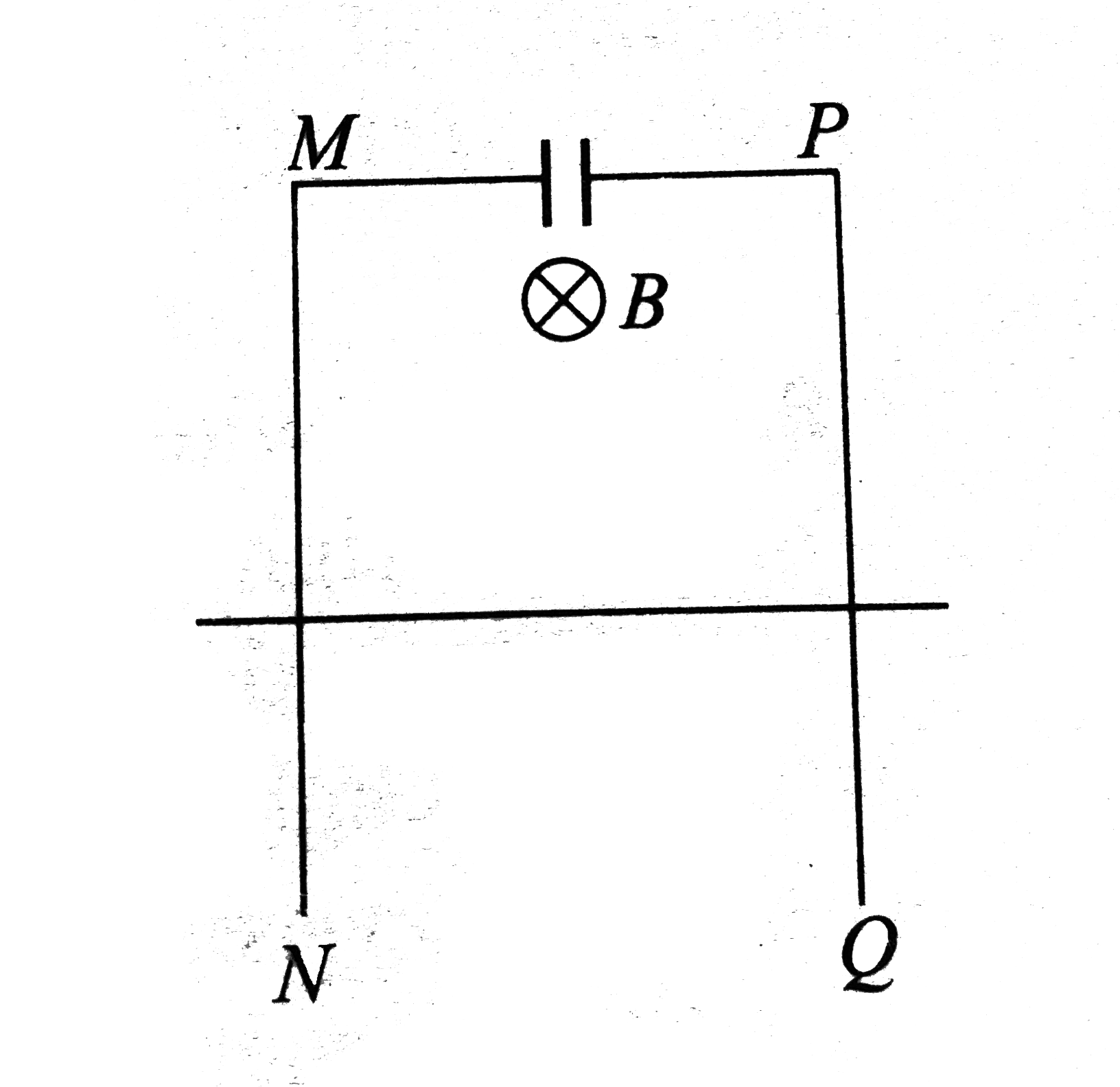 View Solution
Question 204
The magnetic field of a cylindrical magnet that has a pole face radius 2.8cm can be varied sinusoidally between the minimum value 16.8T and the maximum value 17.2T at a frequency of 50/πHz. Cross section of the magnetic field created by the magnet is shown in Fig. 3.211. At a radial distance of 2cm from the axis, find the amplitude of the electric field (∈unitsof×102mNC−1) induced by the magnetic field variation.
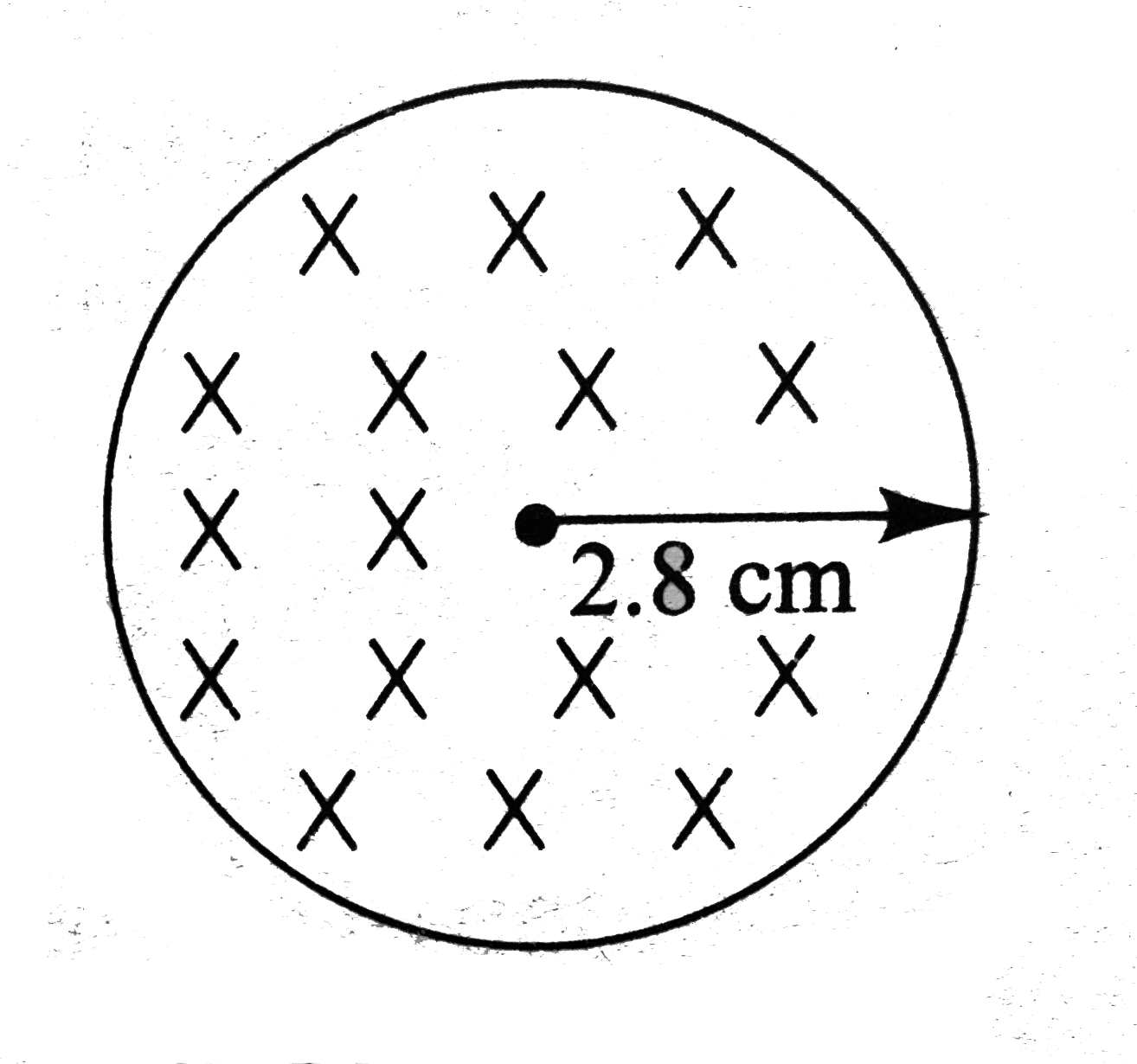 View Solution
Question 205
a long coaxial cable consists of two thin-walled conducting cylinder carries a steady current 0.1A, and the outer cylinder provides the return path for that current. The current produced a magnetic field between the two cylinders. Find the energy stored in the magnetic field for length 5m of the cable. Express answer in Nj (use 1n2=0.7). View SolutionQuestion 206
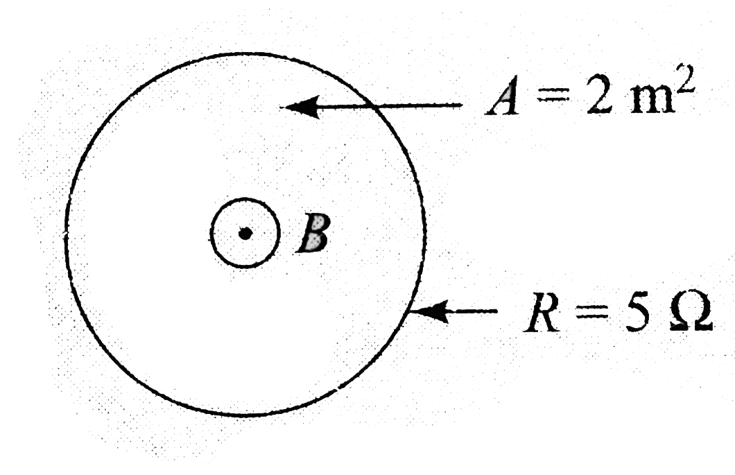
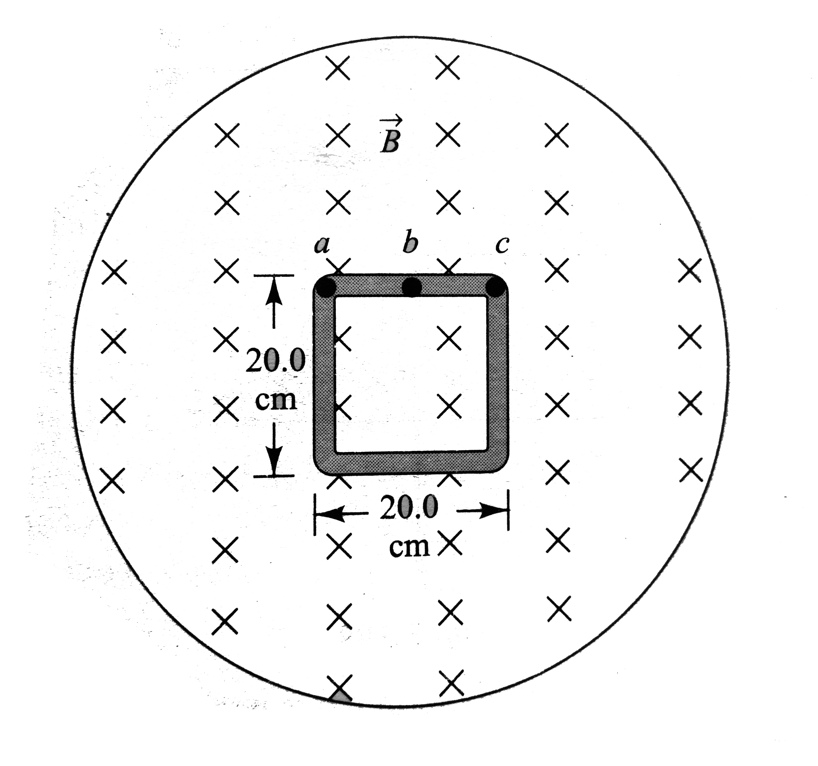
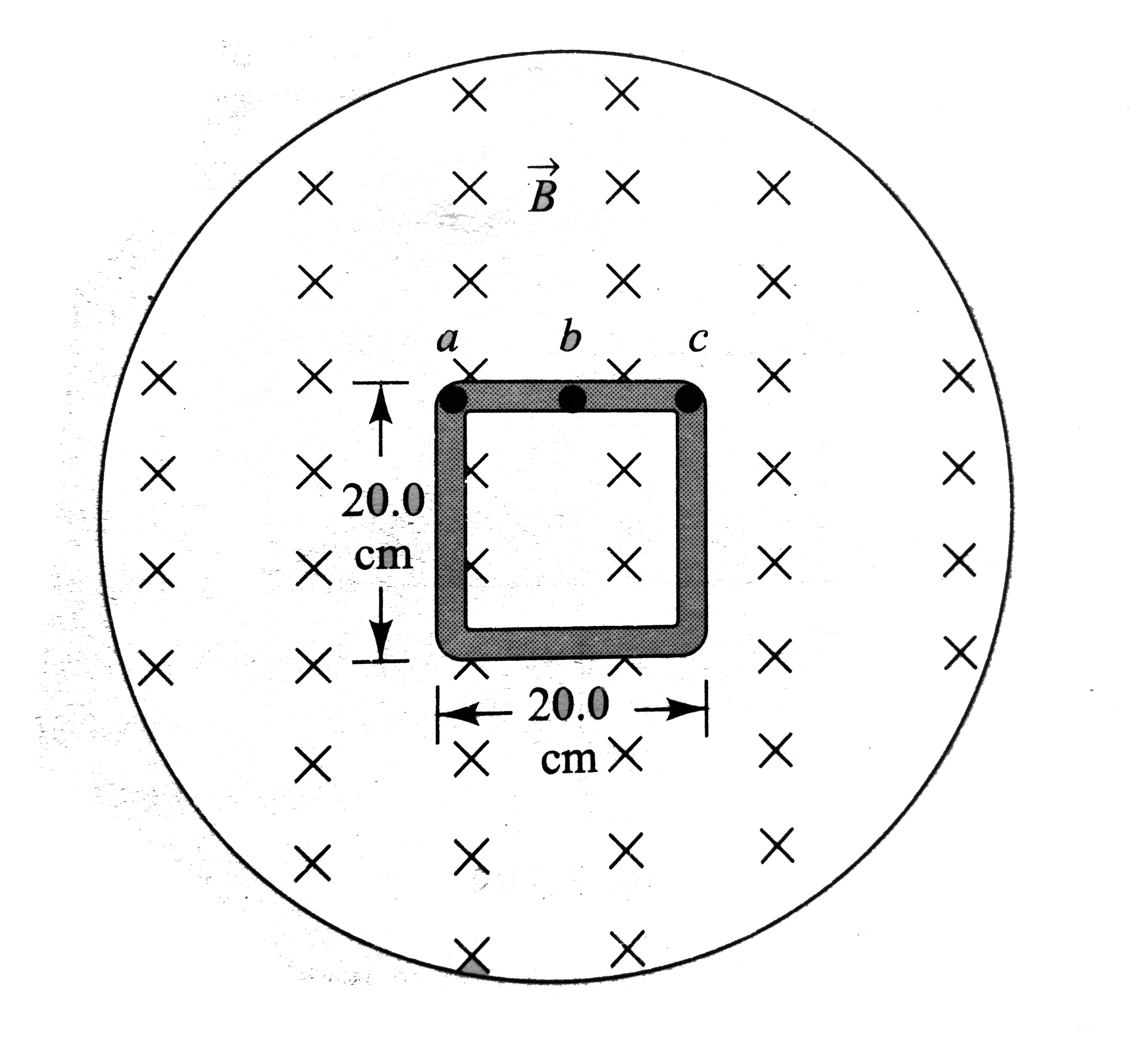
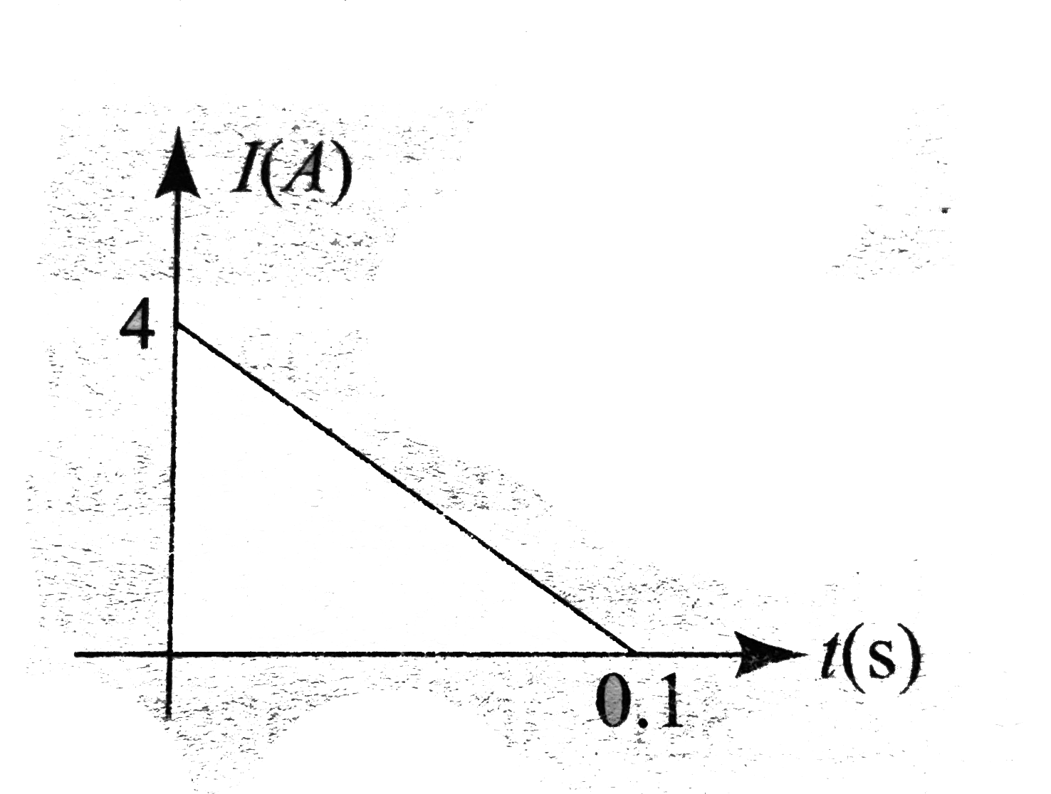
A circular coil of wire consists of exactly 100 turns with a total resistance 0.20Ω. The area of the coil is 100cm2. The coil is kept in a uniform magnetic field B as shown in Fig. 3.212. The magnetic field is increased at a constant rate of 2Ts−1. Find the induced current in the coil in A.
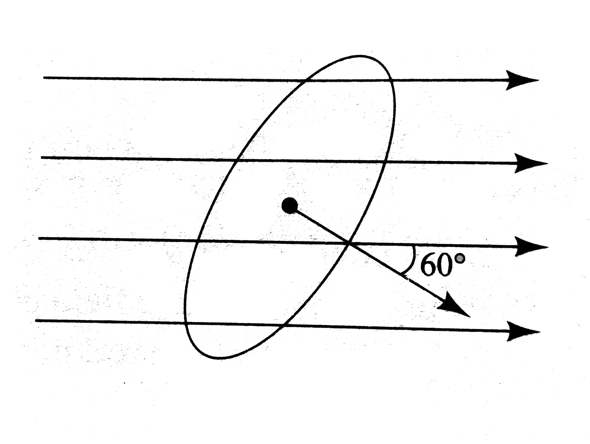 View Solution
Question 208
In Fig. there are two sliders and they can slide on two frictionless parallel wires in uniform magnetic field B, which is present everywhere. The mass of each slider is m, resistance R and initially these are at rest. Now, if one slider is given a velocity v0=16ms−1, what will be the velocity (in ms−1)) of other slider after long time ? (neglect the emf self-induction)
 View Solution
Question 209
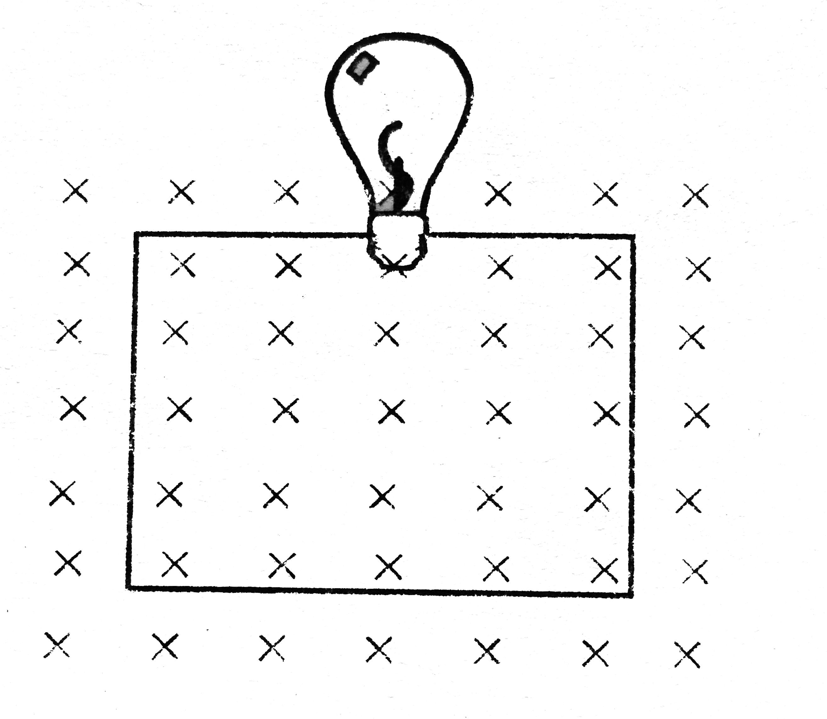
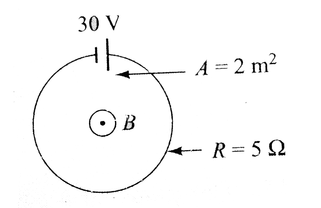
A square wire loop of 10.0cm side lies at right angles to a uniform magnetic field of 7T. A 10V light bulb is in a series with the loop as shown in Fig. 3.125. The magnetic field decreasing steadily to zero over a time interval Δt. For what value of Δt (im ms), the bulb will shine with full brightness?
 View Solution
Question 214
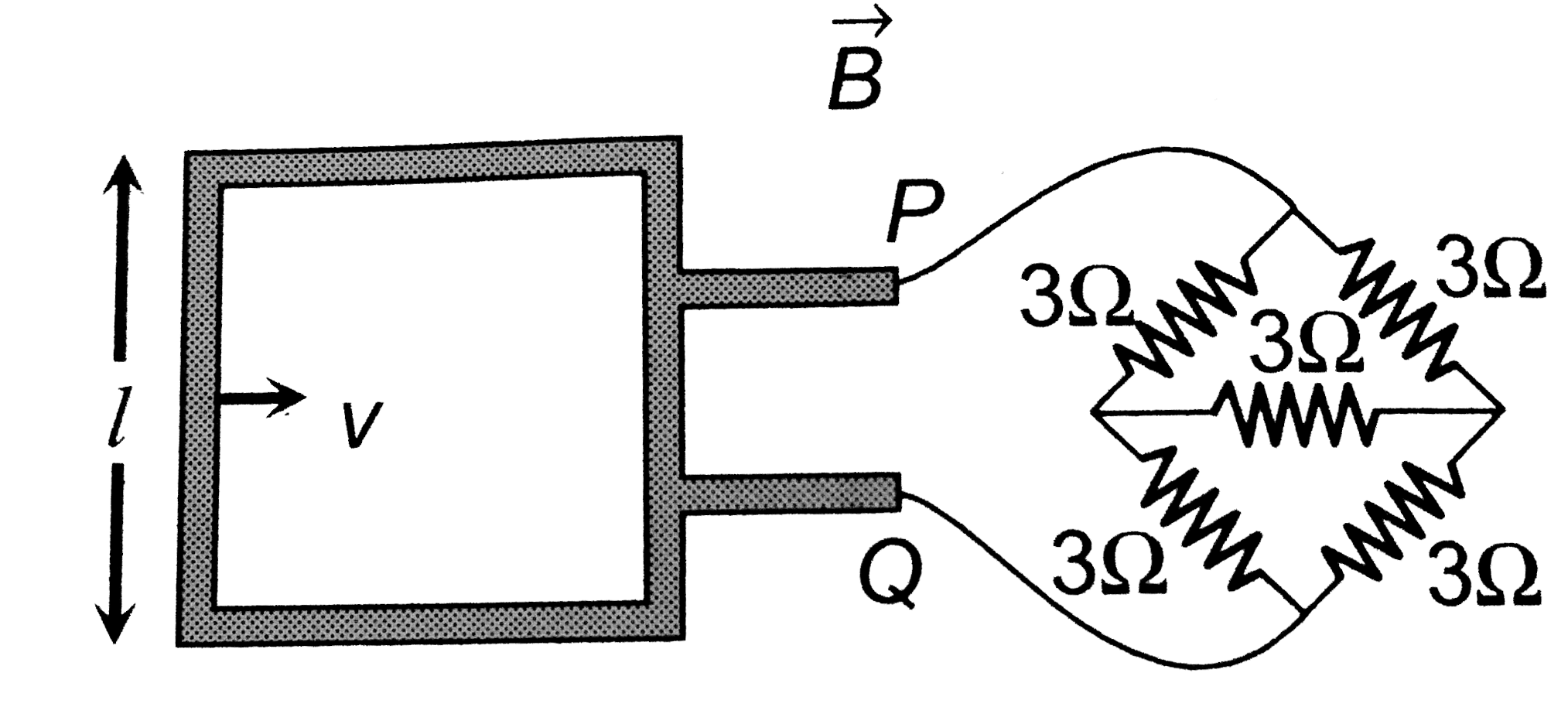
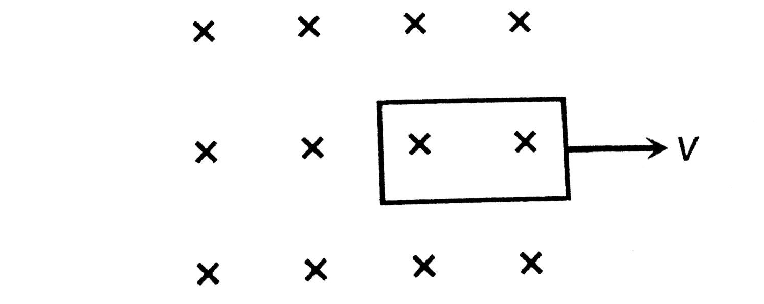
A square metallic wire loop of side 0.1 m and resistance of 1Ω is moved with a constant velocity in a magnetic field of 2wb/m2 as shown in figure. The magnetic field field is perpendicular to the plane of the loop, loop is coonected to a network of resistances. what should be the velocity of loop so as to have a steady current of 1mA in loop?
 View Solution
Question 215
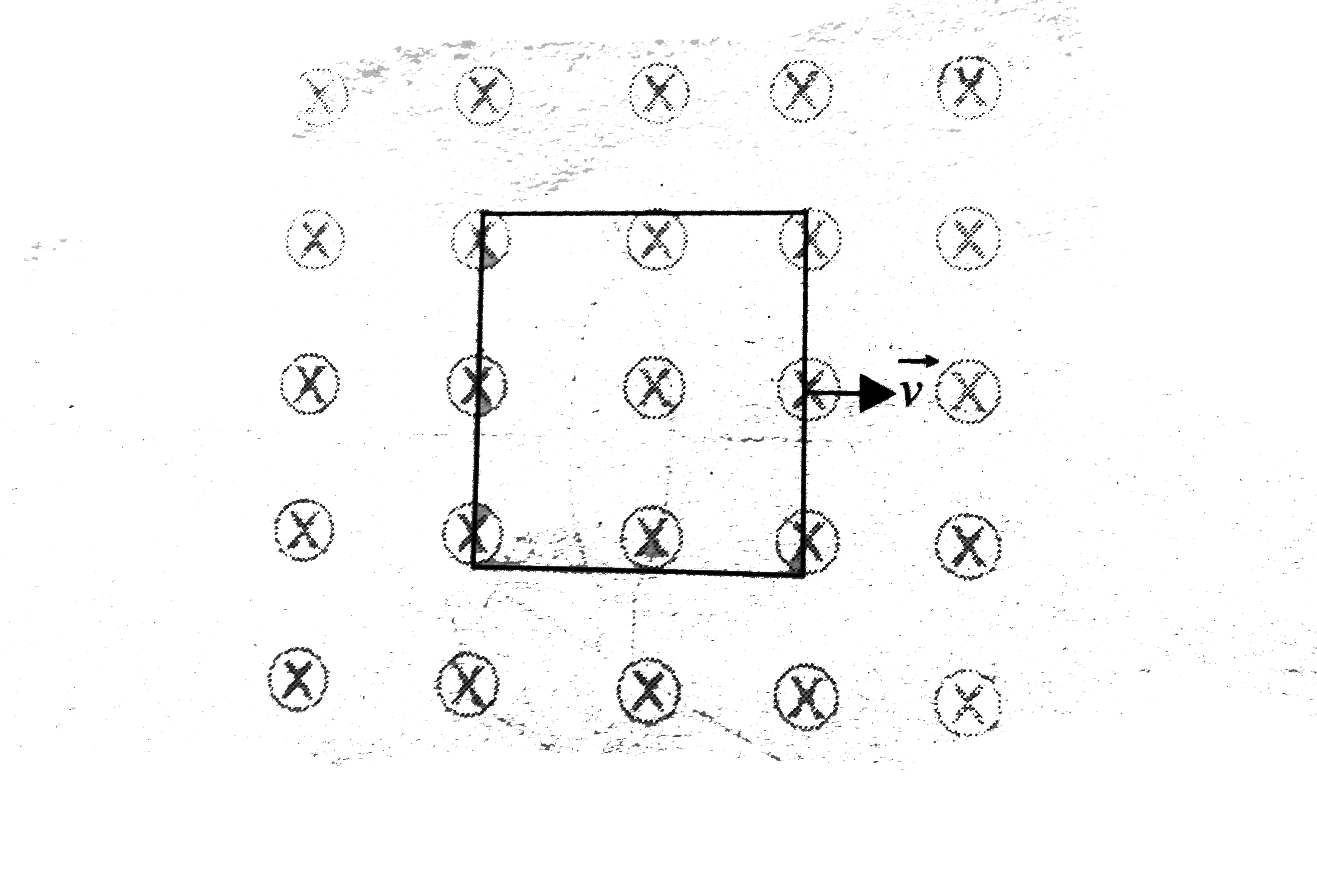
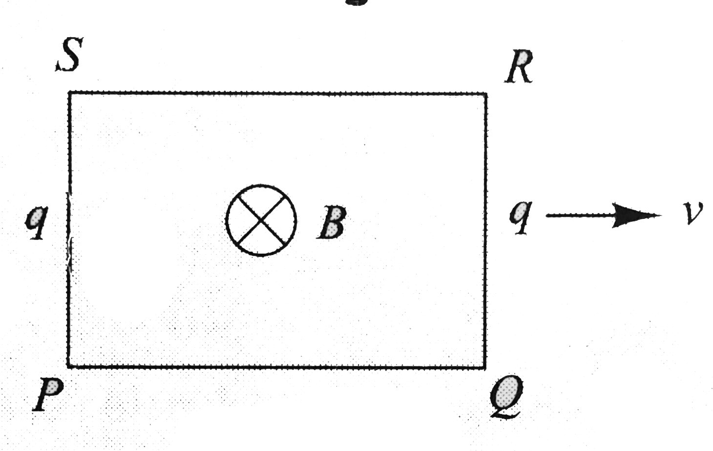
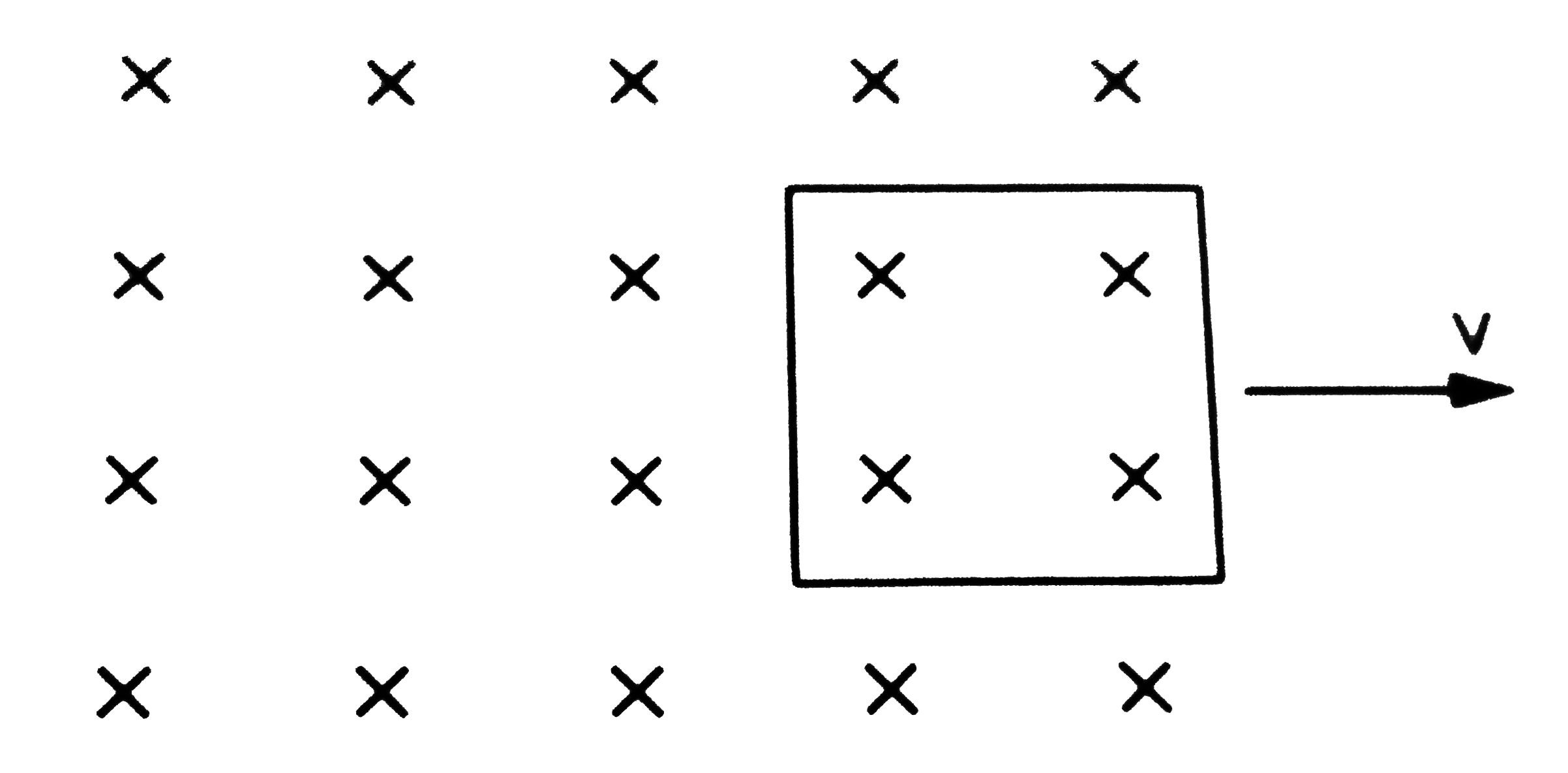
Conducting square loop of side L and resistance R moves in its plane with a uniform velocity v perpendicular to one of its sides. A magnetic induction B, constant in time and space, pointing perpendicular and into the plane of the loop exists everywhere.
The current induced in the loop is
 View Solution
Question 216
A thin circular ring of area A is held perpendicular to a uniform magnetic field of induction B. A small cut is made in the ring and a galvanometer is connected across the ends such that the total resistance of the circuit is R. When the ring is suddenly squeezed to zero area, the charge flowing through the galvanometer is View SolutionQuestion 222
As shown in the figure, P and Q are two coaxial conducting loops separated by some distance. When the switch S is closed, a clockwise current IP (as seen by E) and an induced current IQ1 flows in Q. The switch remains closed for a long time. when S is opened, a current IQ2 flows in Q. Then the direction IQ1andIQ2 (as seen by E) are
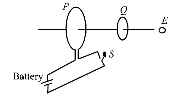 View Solution
Question 224
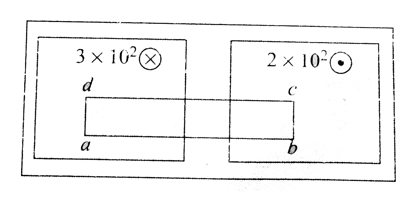
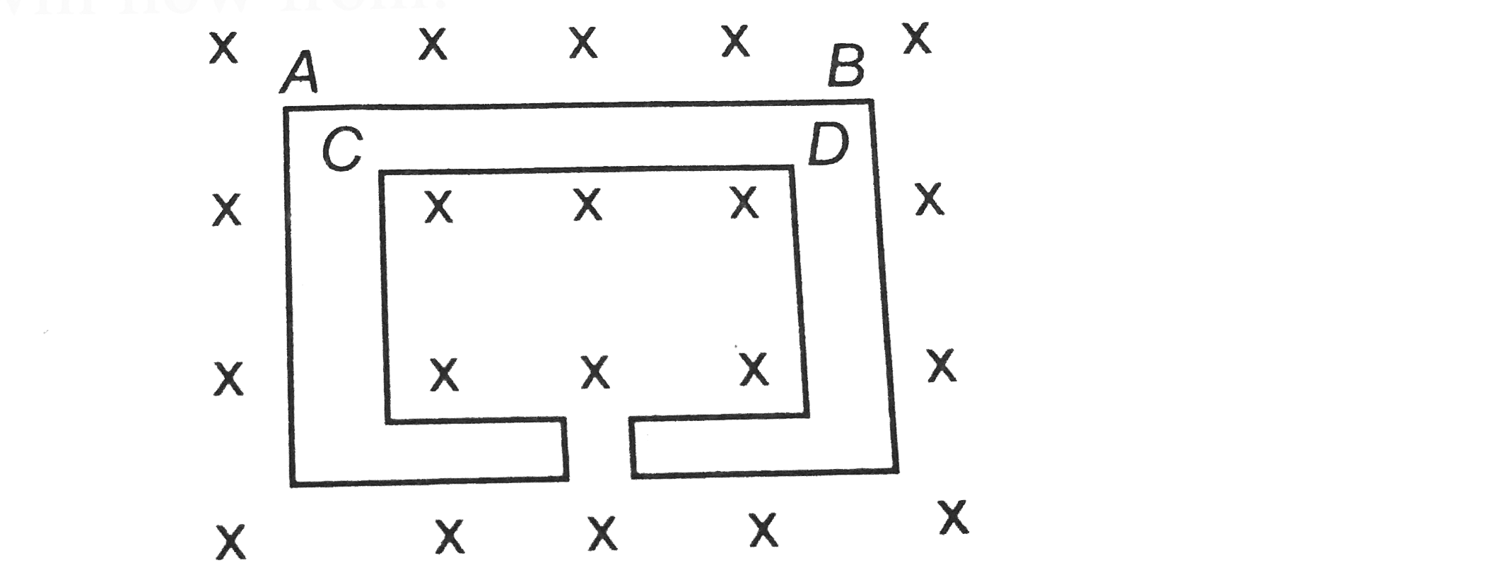
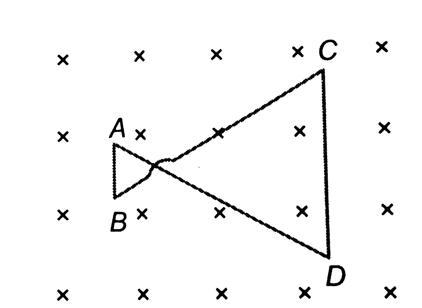
The figure shows certain wire segments joined together to form a coplaner loop. The loop is placed in a perpendicular magnetic field in the direction going into the plane of the figure. The magnitude of the field increases with time I1andI2 are the currents in the segments ab and cd. Then,
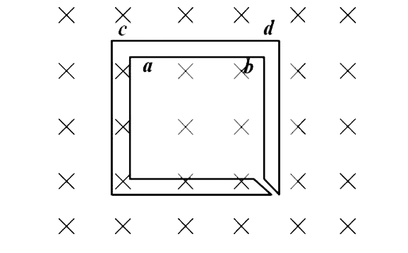 View Solution
Question 225
Conducting square loop of side L and resistance R moves in its plane with a uniform velocity v perpendicular to one of its sides. A magnetic induction B, constant in time and space, pointing perpendicular and into the plane of the loop exists everywhere.
The current induced in the loop is
 View Solution
Question 226
Two metallic rings AandB, identical in shape and size but having different reistivities ρAandρB, are kept on top of two identical solenoids as shown in the figure . When current I is switched on in both the solenoids in identical manner, the rings AandB jump to heights hAandhB, repectively , with hA>hB . The possible relation(s) between their resistivities and their masses mAandmB is(are)
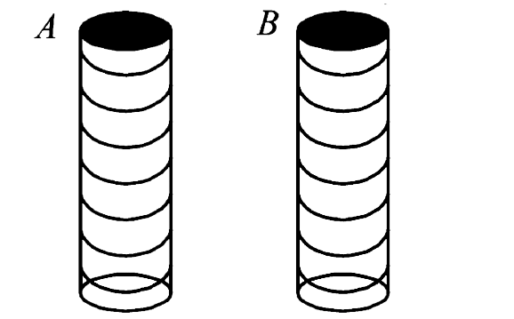 View Solution
Question 228
Statement-1: A vertical iron rod has coil of wire wound over it at the bottom end. An alternating current flows in the coil. The rod goes through a conduction ring as shown in the figure. The ring can float at a certain height above the coil.
Statement -2: In the above situation a current is induced in the ring which interacts with the horizontal components of the magnetic field to produce an average force in the upward direction.
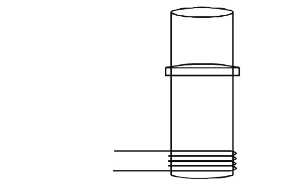 View Solution
All Exercises from CENGAGE PHYSICS (HINGLISH) Class 12 PHYSICS ELECTROMAGNETIC INDUCTION
- ARCHIVES ASSERTON - REASONING
- ARCHIVES FILL IN THE BLANKS
- ARCHIVES MULTIPLE CORRECT
- ARCHIVES SINGLE CORRECT
- COMPREHENSIVE
- COMPREHENSIVE TYPE
- COMPRESSION TYPE
- EXERCISE 3.1
- EXERCISE 3.2
- EXERCISES ASSERTON - REASONING
- EXERCISES INTEGER
- EXERCISES LINKED COMPREHENSION
- EXERCISES MULTIPLE CORRECT
- EXERCISES SINGLE CORRECT
- EXERCISES SUBJECTIVE
- MULTIPLE CORRECT ANSWER TYPE
- SINGLE CORRECT
- SINGLE CORRECT
- SINGLE CORRECT ANSWER
- SINGLE CORRECT ANSWER TYPE
- SUBJECTIVE TYPE
- ILLUSTRATION
- SOLVED EXAMPLE



 .
.